4
$\begingroup$

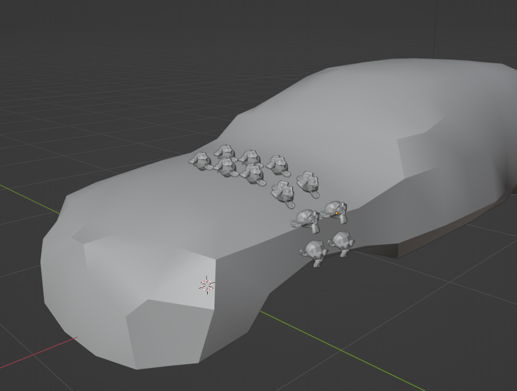
i want to cover my target mesh completely with lots of small objects. I don't want to do it by hand and ideally i can control the size of the small objects and maybe even animate them. The objects should orient to the normal of the target in that specific location and be placed in a grid. the target actually is not important as it will be deleted afterwards

i did this mockup to illustrate my goal to you guys

enter image description here

my approaches with array and shrinking didn't work out. any help would be greatly appreciated

$\endgroup$
1
  • $\begingroup$ Hi :). What have you tried so far? Particles? Geometry nodes? Instancing? $\endgroup$ Commented Feb 2, 2022 at 16:52

2 Answers 2

4
$\begingroup$

You can certainly achieve similar effect with Hair particles.

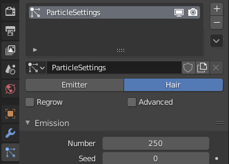
  1. Add a particle system to your object and change it from Emitter to Hair

Hair particles

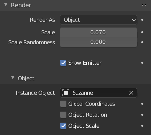
  1. In Render section, set Render As to Object. In Object submenu, pick the object you want to be scattered - in my case it is Suzanne, the monkey. Checking different checkboxes and setting Scale Randomness produces interesting results, definitely try it :)

Render settings

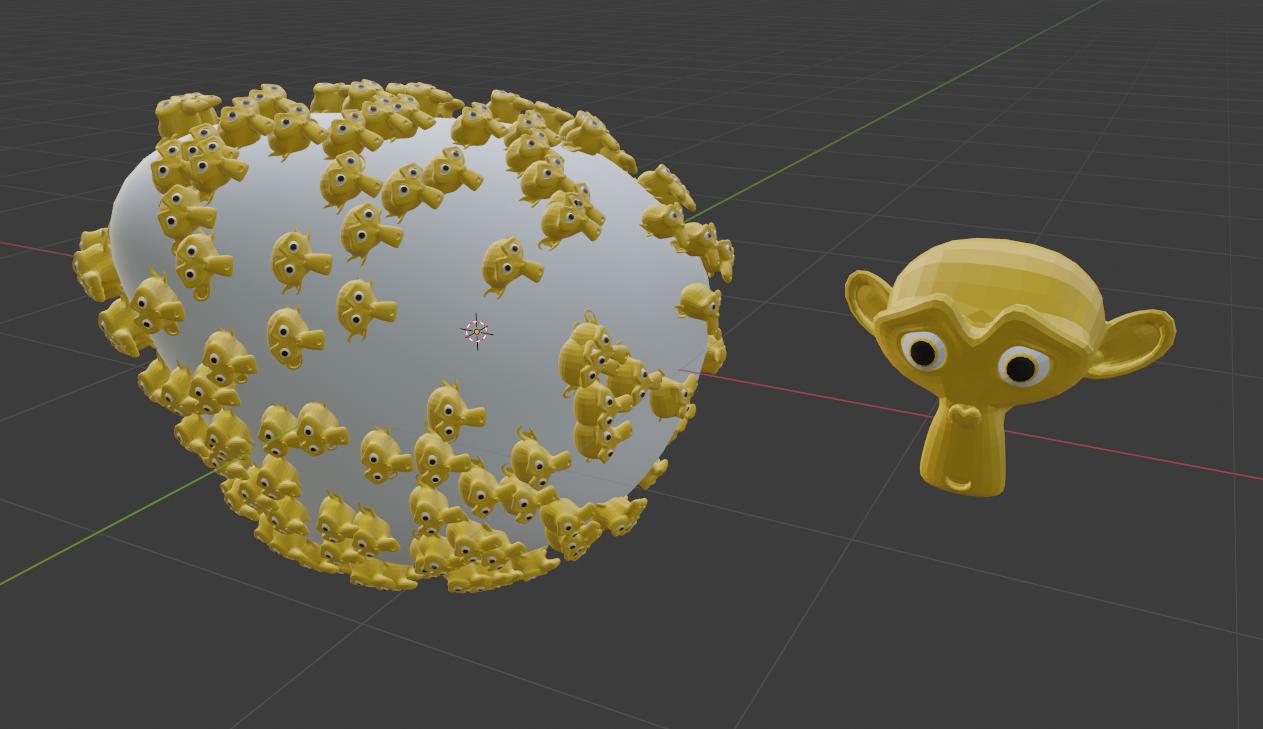
  1. In Emission section at the top, you can control the number of objects generated. I distorted a UV sphere as my object to demonstrate - 250 monkeys are enough for my liking.

Sphere covered by yellow monkeys

  1. If you want a grid layout as in your example picture, go to Emission -> Source. Leave Distribution on Jittered, but uncheck Random Order, set Particles/Face to 1 (You want a single object on every grid face) and the Jittering Amount to 0. Higher in Emission, set the Number of hairs sufficiently high - to the same or higher number as the number of faces you have on the object.

Monkeys on a grid layout

Hope this helps!


You can check out this guide for similar process - covering a plane with trees.

$\endgroup$
1
  • 1
    $\begingroup$ thank you very much for your time and detail tutorial. unfortunately i couldn't get an even distribution on my target mesh with that method. $\endgroup$
    – Coccolino
    Commented Feb 3, 2022 at 13:24
4
$\begingroup$

Geometry Nodes

With Geometry Nodes, I can start you off, and perhaps some other users will come up with better tips.

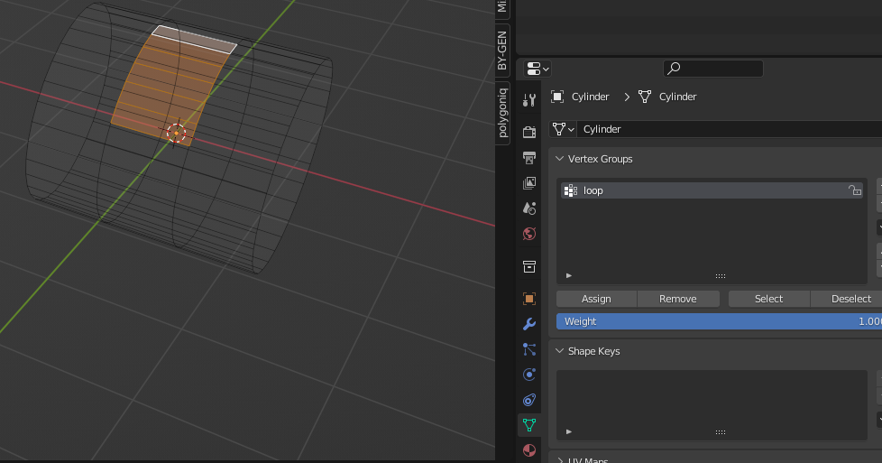
a. First, select your main object, go to edit mode and select the target faces where you want Suzannes to go.

b. Go to Object Data Properties and then with the + sign add a new group. Assign your selection to this group, and make sure that works by selecting and deselecting. Call it a name like "loop". enter image description here

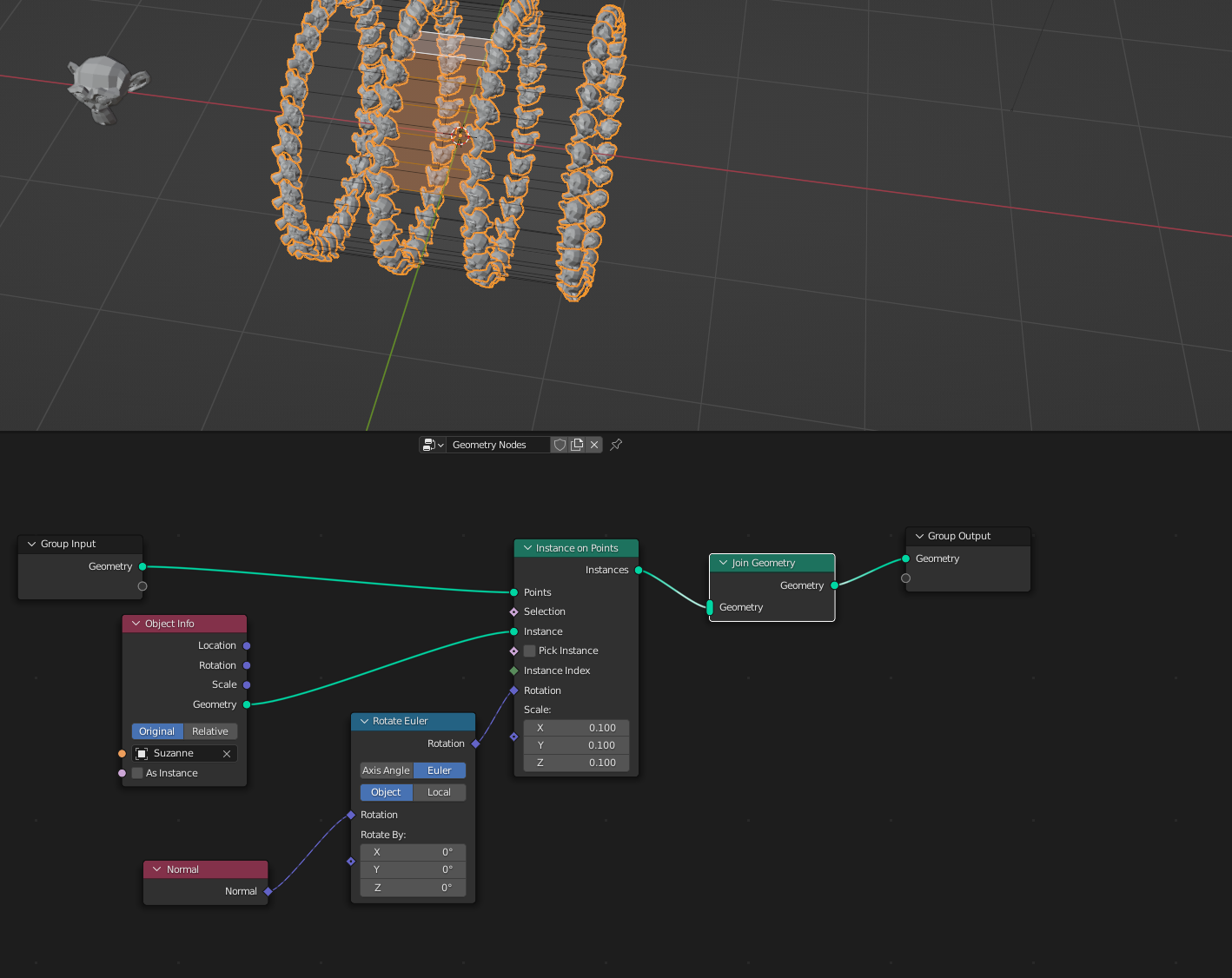
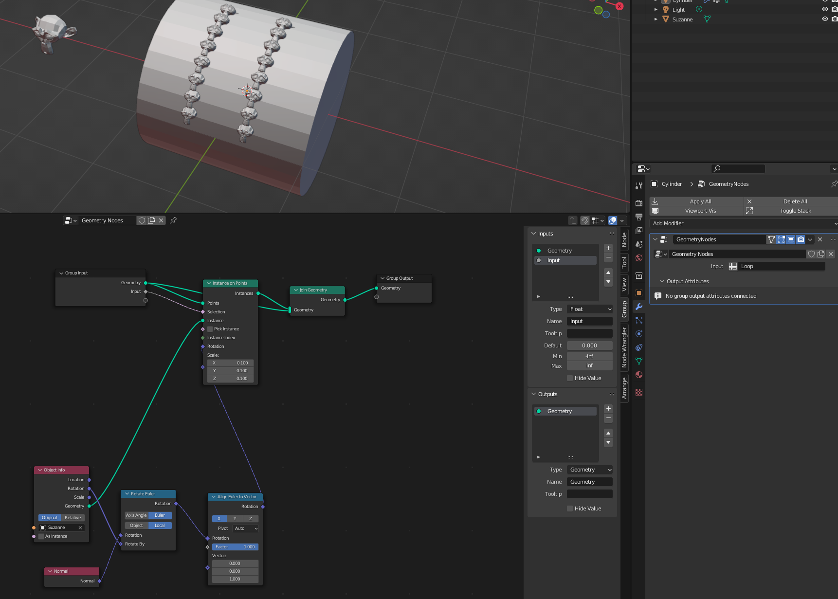
c.Then, in a bottom window open geometry nodes, create a new node tree, and copy the nodes which I have here. Shift+A will open the list of possible nodes.

enter image description here

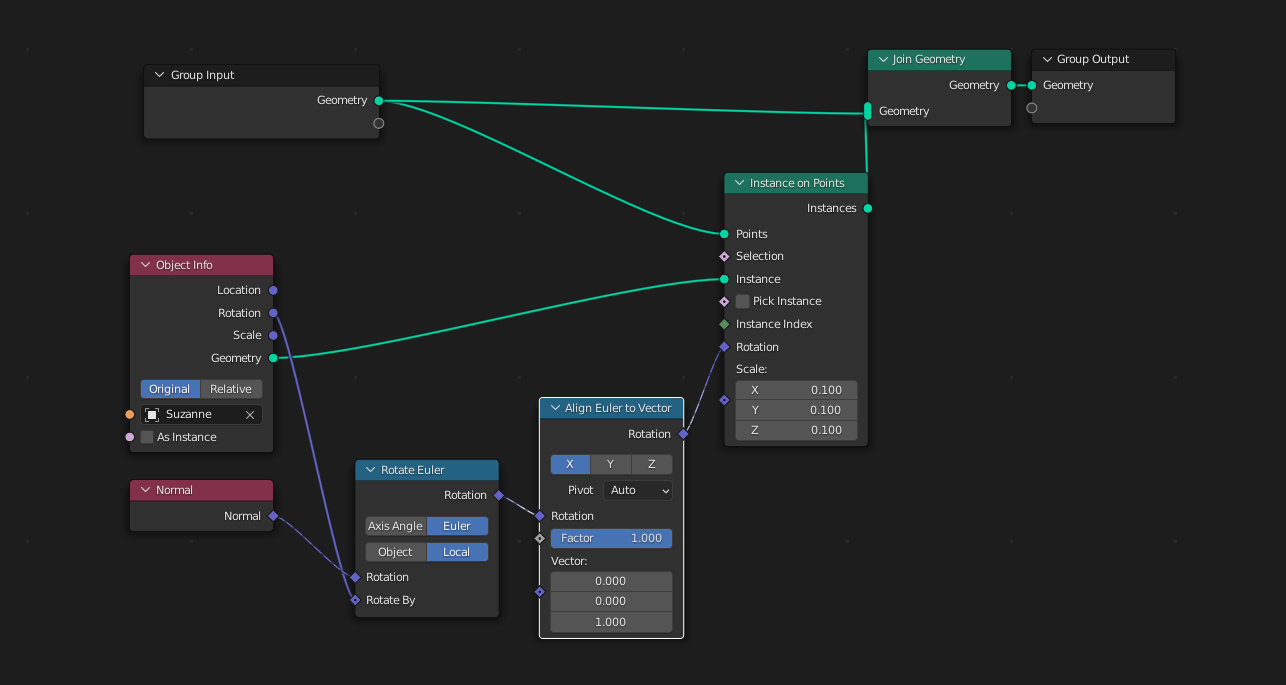
If you are unsatisfied with the rotation, you can add an Align Euler to Vector node.

enter image description here

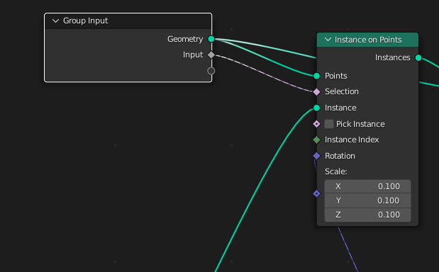
e. Select the group input node, and press N to pull out the options, with the + sign, add an input like this.

enter image description here

f. Connect the input to the selection node on "instance on points" enter image description here

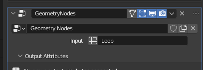
g. Go back to your modifier tab and in the geometry nodes modifier choose your "Loop" group

enter image description here

h.Here is the result:

enter image description here

$\endgroup$
3
  • $\begingroup$ thank you so much for your detailed step by step. it definitely pointed me towards the right direction. I will have to dive into that whole thing, as I have not worked with geometry nodes before. my objects are now distributed to every vertex, which is not necessarily evenly spread. is this possible to do this with nodes as well, or do i have to do a even retopo of my target mesh? $\endgroup$
    – Coccolino
    Commented Feb 3, 2022 at 13:23
  • $\begingroup$ As you say, the "Instance to Points" node, exactly positions the Suzannes on each vertex. That retopo idea is one approach but not the only one. $\endgroup$ Commented Feb 3, 2022 at 13:55
  • $\begingroup$ Notice that, I can make the main object invisible, leaving only the Suzannes visible by disconnecting it from the "Join Geometry Node". You can bring in surfaces or objects only to use their points as positions. I hope this helps. $\endgroup$ Commented Feb 3, 2022 at 14:21

You must log in to answer this question.

Not the answer you're looking for? Browse other questions tagged .