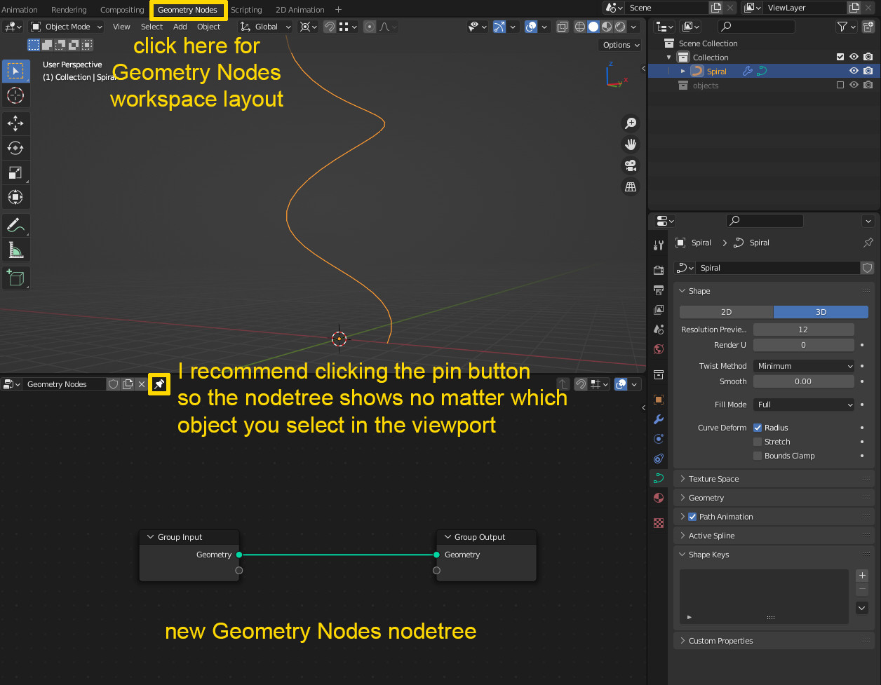
An example how to do this in Geometry Nodes, best would be to use the Geometry Nodes wokspace layout by clicking it at the top menu bar.
In your example you have a single object if I see it correctly (you don't need the plane for this version)? But if not, you can select all objects you want to place on the curve and press M > New Collection and give it a name.
Select the Spiral object, go into the Geometry Nodes Editor window and click New. Now a new nodetree appears with just two nodes: a Group Input and a Group Output. Without giving a full tutorial let's just say this, the input provides the original data of the curve and sends it to the output so that it produces the curve. And we can manipulate things inbetween.

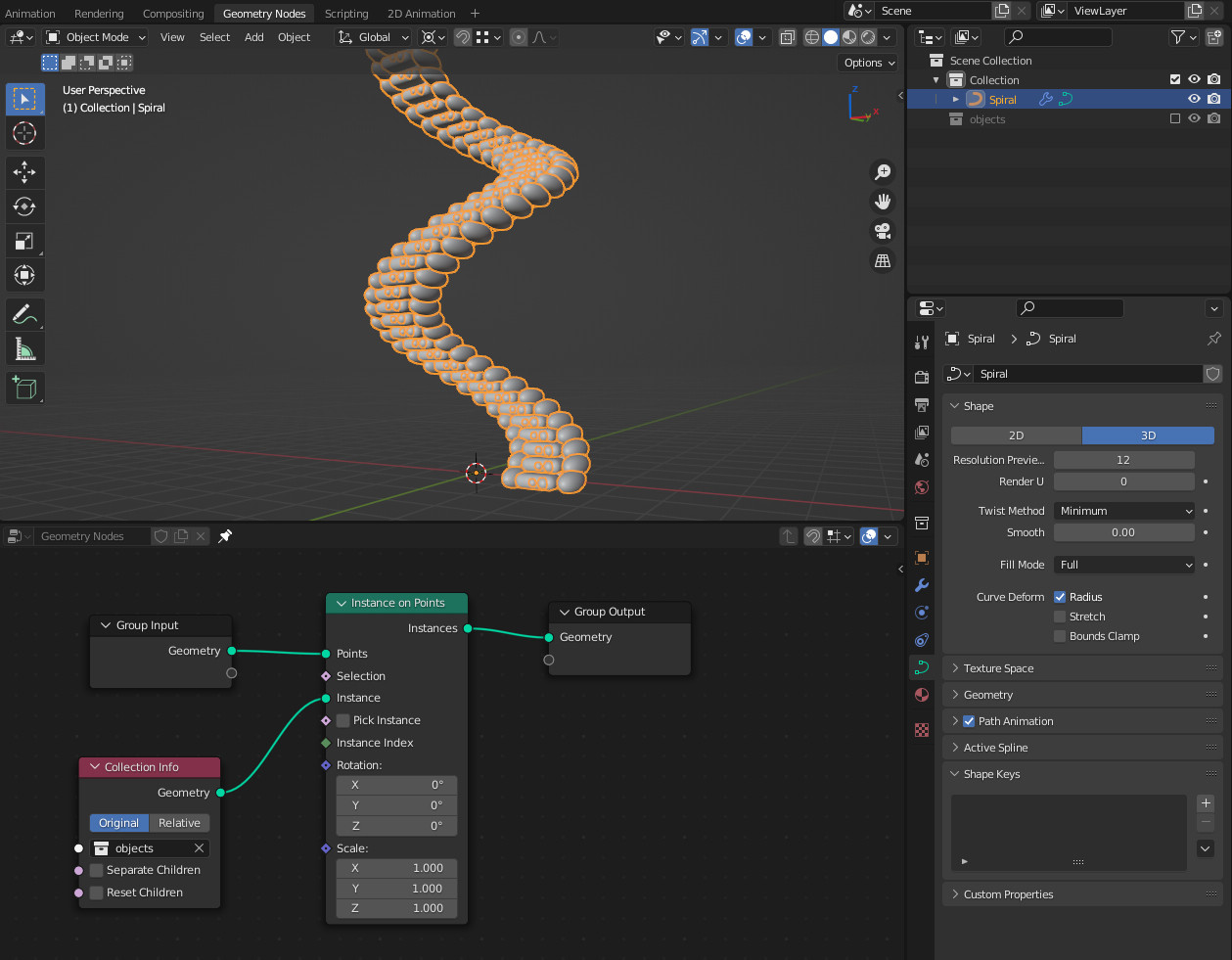
- Drag the object (or collection of objects) which you want to place along the curve from the Outliner into the nodetree. If it's a collection, make sure Separate Children is not enabled.

- Now add a new node, Shift+A > Add > Instances > Instance on Points (not to be confused with the Instances to Points node!) and plug it between Group Input and Group Output, the input's Geometry into Points input, the Instances output into the Geometry group output. The collection's Geometry output goes into Instance. Okay, too many similar confusing terms, here's a picture - you can immediately see that the objects are placed on the curve:

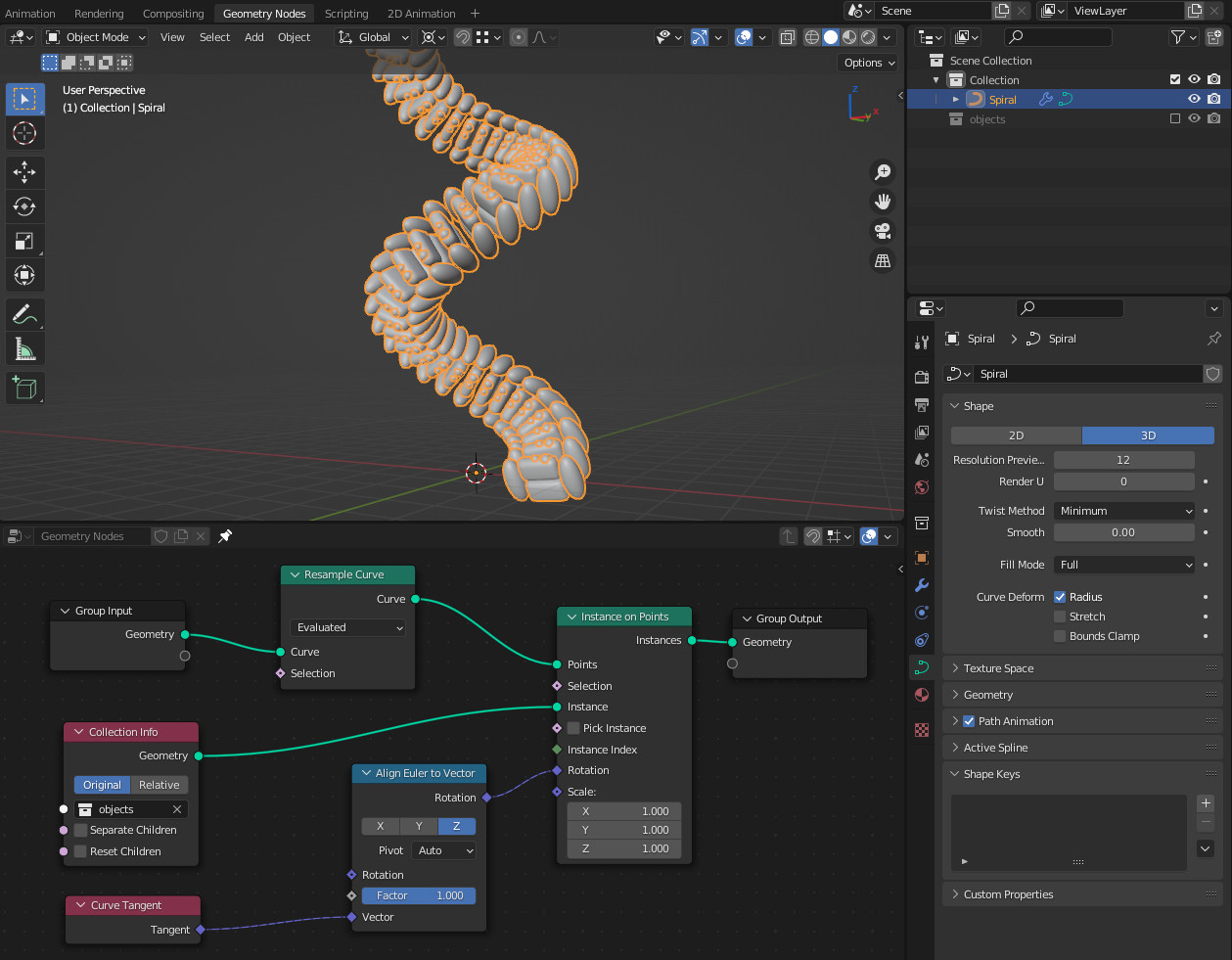
- One object (collection) is placed on each vertex of the curve. If you are not happy with the amount, you can change it with a Resample Curve node (Shift+A > Add > Curve). You can set a different Count if you want a certain number of elements or a Length, if you want them all to be 0.2 meters apart from each other for example.

- Now you have them all aligned just in the object's (collection's) default orientation. If you want to align them with the curve tangent, you need two more nodes: a Curve Tangent node (Shift+A > Add > Curve) and the Align Euler to Vector node (Shift+A > Add > Utilities). Plug the Tangent output of the first node into the Vector input of the second node, there select the alignment to Z and set Pivot to Auto. Then plug the Rotation output into the Rotation input of the Instance on Points node. Again, confusing terms, here's a picture:

This should do what you want if I understand the question correctly.
//EDIT: To rotate the instances on their local axes, you can plug a Rotate Euler node after the Align Euler to Vector node. Set it to Euler and Local and you can enter values in degrees for each axis. To increase the rotation per instance you can multiply the rotation per step with the indices of the instances. They always start with 0, so let's say you want 10°, the first won't be rotated, the next 1 × 10°, then 2 × 10° etc. To decide on which axis to rotate you can plug the degrees into a Combine XYZ node, however (although the Rotate Euler works with degrees), the Combine XYZ interprets them as radians. So to make it easy and not have to convert the rotation manually from degrees to radians, just plug a To Radians node after the multiplication. Many words again, hence an image and the blend file below. By the way, this would also work if you do the local rotation before the tangent alignment, you would just leave the Rotation input of the Rotate Euler node empty and instead plug the result into the Rotation input on the Align Euler to Vector node.


