Maybe this is a good place to contrast direct modelling, where you make curved profiles yourself, and subdivision-surface modelling, where you construct a framework, and anticipate how Catmull-Clark subdivision will make curves for you.
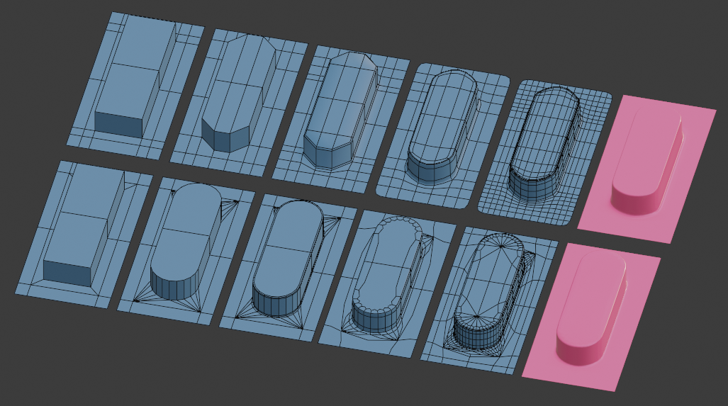
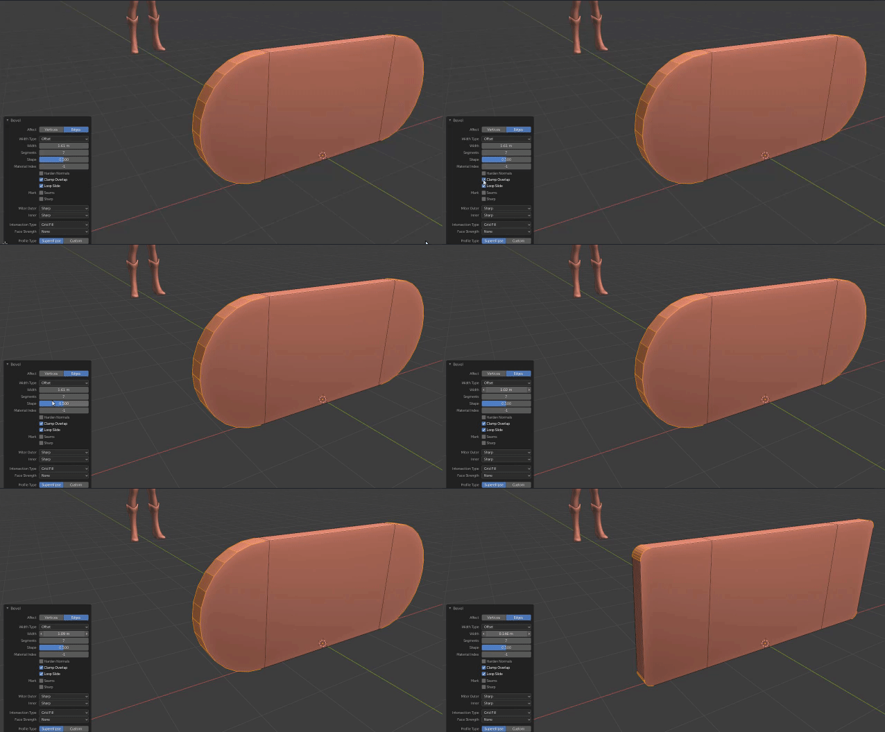
Bottom Row: Direct modelling
On the bottom row, the corner-verticals are selected, and then bevelled with enough segments to give you the curve with the required resolution. (If you bevel with 'Clamp Overlap' on, and take the width as far as you can, you will get a perfect circular arc. There will be duplicate vertices where the bevels meet: you can remove those with M Merge > By Distance)
Then the sharp top and bottom edges of the extrusion are narrowly bevelled too, with a couple of segments, to give smooth-shading some guidance. Without that bevel, the smooth-shading would interpolate normals straight over the transition from the horizontal to vertical faces, with a very unnatural looking result. (You can also guide the smooth-shading by splitting the normals, with Auto Smooth.)
Advantages / Disadvantages:
Up to step 3, so far, so good, for lower-poly modelling. The geometry has a lower resolution, so you can see curves are segmented on close inspection, but the shading makes them look smooth. Long thin triangles have been created in the base plane, but so long as it is flat, so smooth-shading doesn't have to interpolate normals across those, that's fine. This is the kind of topology that Booleans, and CAD packages, often generate.
The direct approach has advantages, up to step 3: it's quick, and limits the number of edges propagating across the model. The disadvantages become apparent at step 4, if you want to use a Subdivision Surface modifier. The triangles have broken the flow of face loops. If you do need to subdivide the geometry for higher resolution, that does not play well. Also, a lot of Blender's (and other applications') tools are geared to selecting, inserting, and sliding loops of consecutive quadrilateral faces. The triangles make the model harder to adjust, further down the line.
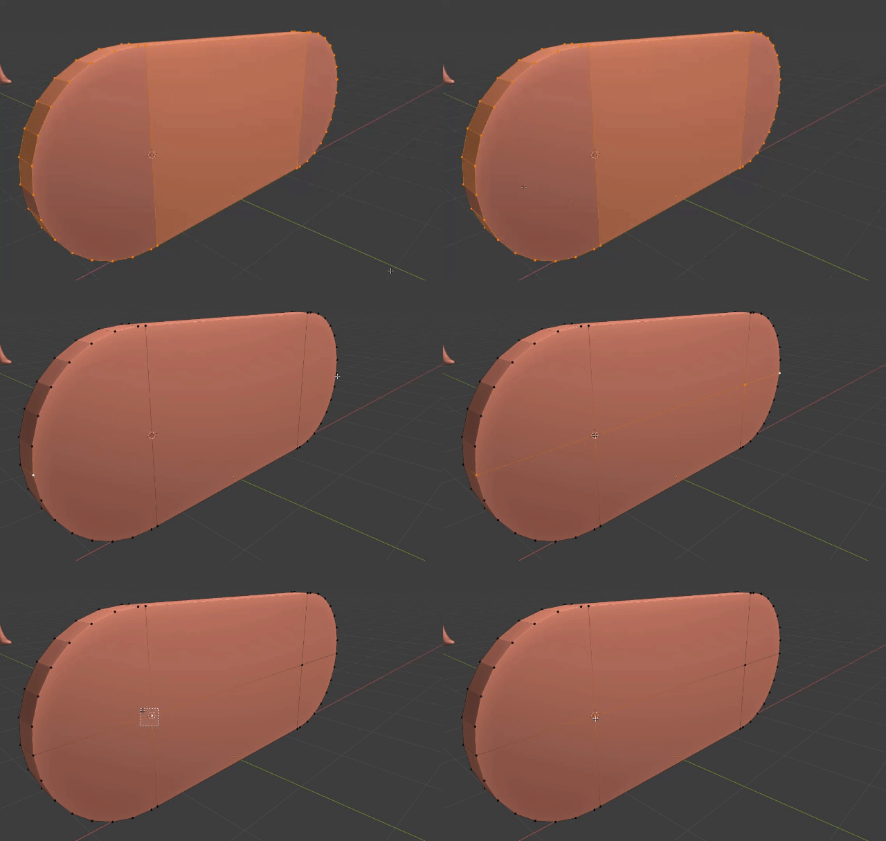
Top Row: Subdiv. Modelling
Here, a couple of extra loops are CtrlR cut down the length of the extrusion, and the corners are scaled back to give it half-hexagon ends. Again, at step 3, the sharp edges are bevelled, to hold the normals. Some loops are cut across the extrusion, too. These are optional, but can be used to control the curvature that's generated by the Catmull-Clark subdivision modifier at step 4. Step 4 in both rows shows the result of 2 levels of subdivision, optimally displayed, and the 5th copy shows all the edges generated by the subdiv.
