0
$\begingroup$

I want to have a bone that drives another object's y location according to its(the bone's) local y axis.

enter image description here

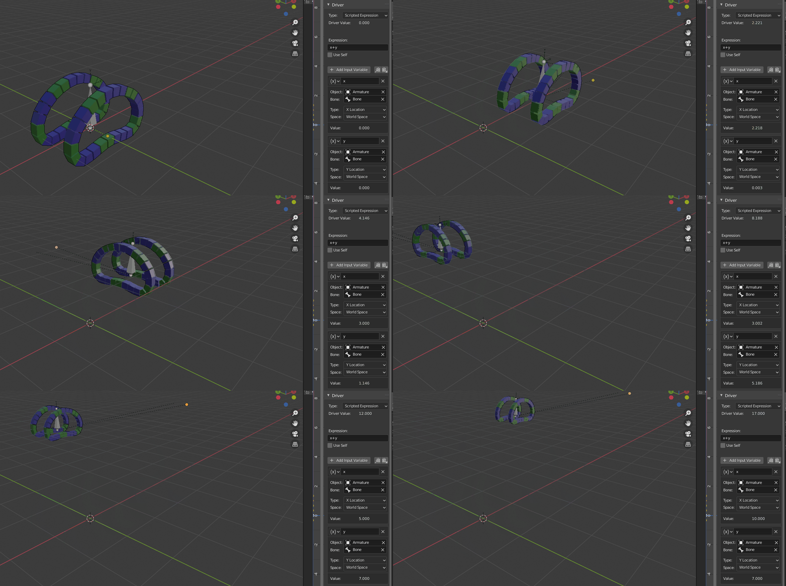
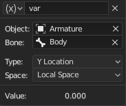
this is the driver I'm using.

In this case the driver is working(The driver is what is making the wheels move.)

https://i.sstatic.net/rRLBx.jpg

However when I rotate the bone on the Z axis ( the local y axis is supposed to have rotated too but the driver doesn't work as expected)

as seen here https://i.sstatic.net/nspvg.jpg

the driver is working on the armature's local axis. How can I make it so that it applies on the bone's local axis instead

Edit: I tried creating an empty and parented it to the bone and made the empty's local Y the driver and it still gave me the same issue.

Any ideas on how to fix this?

Edit: Added blend file. Play the animation to see what my issue is.

The driver is added to the wheel/

$\endgroup$
3
  • 1
    $\begingroup$ Consider adding detail of driver, not just driver variable. $\endgroup$
    – batFINGER
    Commented Aug 15, 2020 at 15:49
  • $\begingroup$ You should add more information. Without that if one can give a solution to make it work, that still won't explain why your situation is not working. You can upload the file here: blend-exchange.giantcowfilms.com $\endgroup$
    – lemon
    Commented Sep 28, 2020 at 7:21
  • $\begingroup$ @lemon Just added the blend file $\endgroup$
    – Motcho
    Commented Sep 28, 2020 at 21:12

3 Answers 3

2
+50
$\begingroup$

Bones local coordinates are coordinates in the bone rest pose space (initial location/rotation/scale before it moves in pose mode).

The difference between world and local coordinates is the parenting: world coordinates include parent chain transformation up to world.

Though, in local coordinates, moving along (say) X does not mean a movement along current X bone axis. This is still relative to its original rest position.

That's why your setting is not working.

You need to consider both X and Y (local or world won't directly matter in this case) in order to shift the arrayed meshes along the curve.

That can be this setting:

enter image description here

However, the turns are not good: both tracks follow the same speed even if we add the rotation around Z. We would prefer the track which is inside the curve to go slower than the other one.

... this can be handled by some driver functions (won't have time to explain it for now...).

The blend file contains the two versions (with and without speed differential when rotating).

$\endgroup$
1
  • $\begingroup$ Hey man, thanks a lot for the help. I downloaded your blend file and the tracks with the speed differential isn't working. On the drivers page I get an ERROR: Invalid Python expression. I'm guessing it's because blender doesn't recognize the variables Self, right and left.? Again I'm not really sure as I'm still a beginner in python. And while we're on the topic of programming how can I apply the script you made to a different object? $\endgroup$
    – Motcho
    Commented Sep 30, 2020 at 16:12
2
$\begingroup$

It is giving you the local Y location. But the local Y location does not change with rotation. You move, then you rotate:
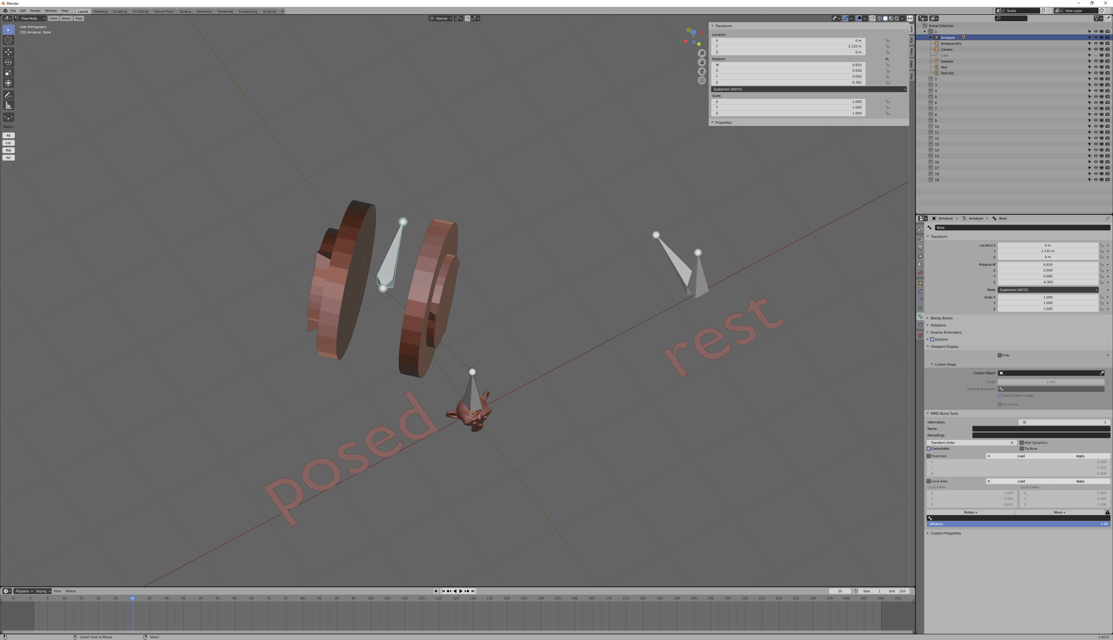
enter image description here

If the driver isn't giving you what you want, then it's not local Y location that you want. But what do you want? Is it the projected distance to this plane, oriented with the driving bone, running through the origin?
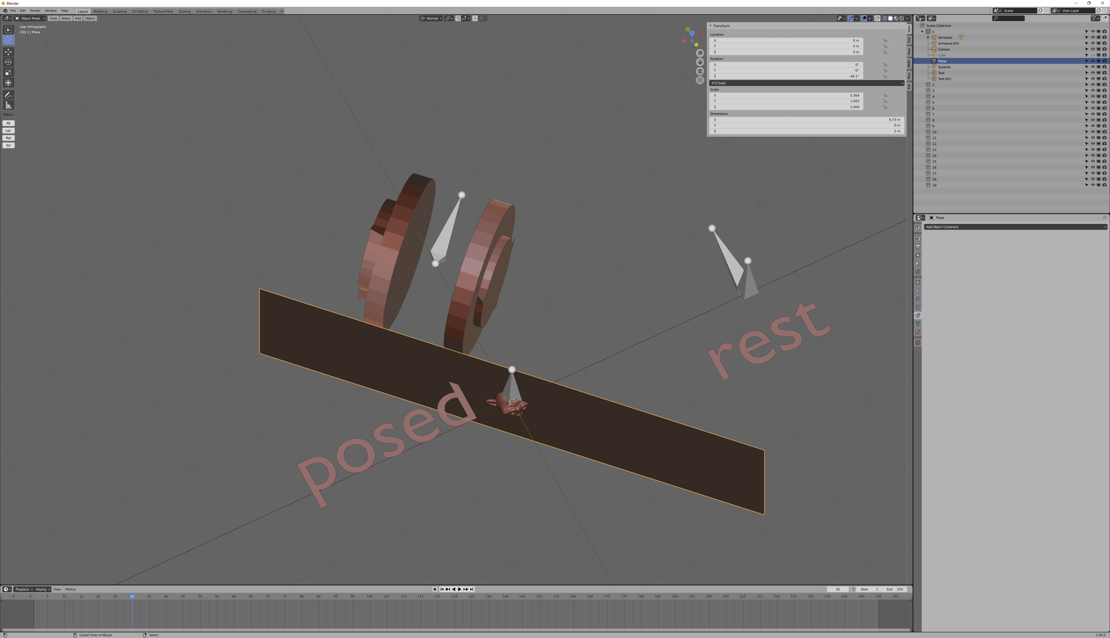
enter image description here

If you want, you can get that distance. Make a bone at the location of your root and parent it to your root, then give it a copy rotation constraint, world->world, targeting your deforming bone. Then create a child bone of the deforming bone, at the same location as the deforming bone, and floor it (with rotation enabled) to the new child of your root. Now you have a bone whose local Y location measures the distance to that plane. Everything you need to know is shown below:
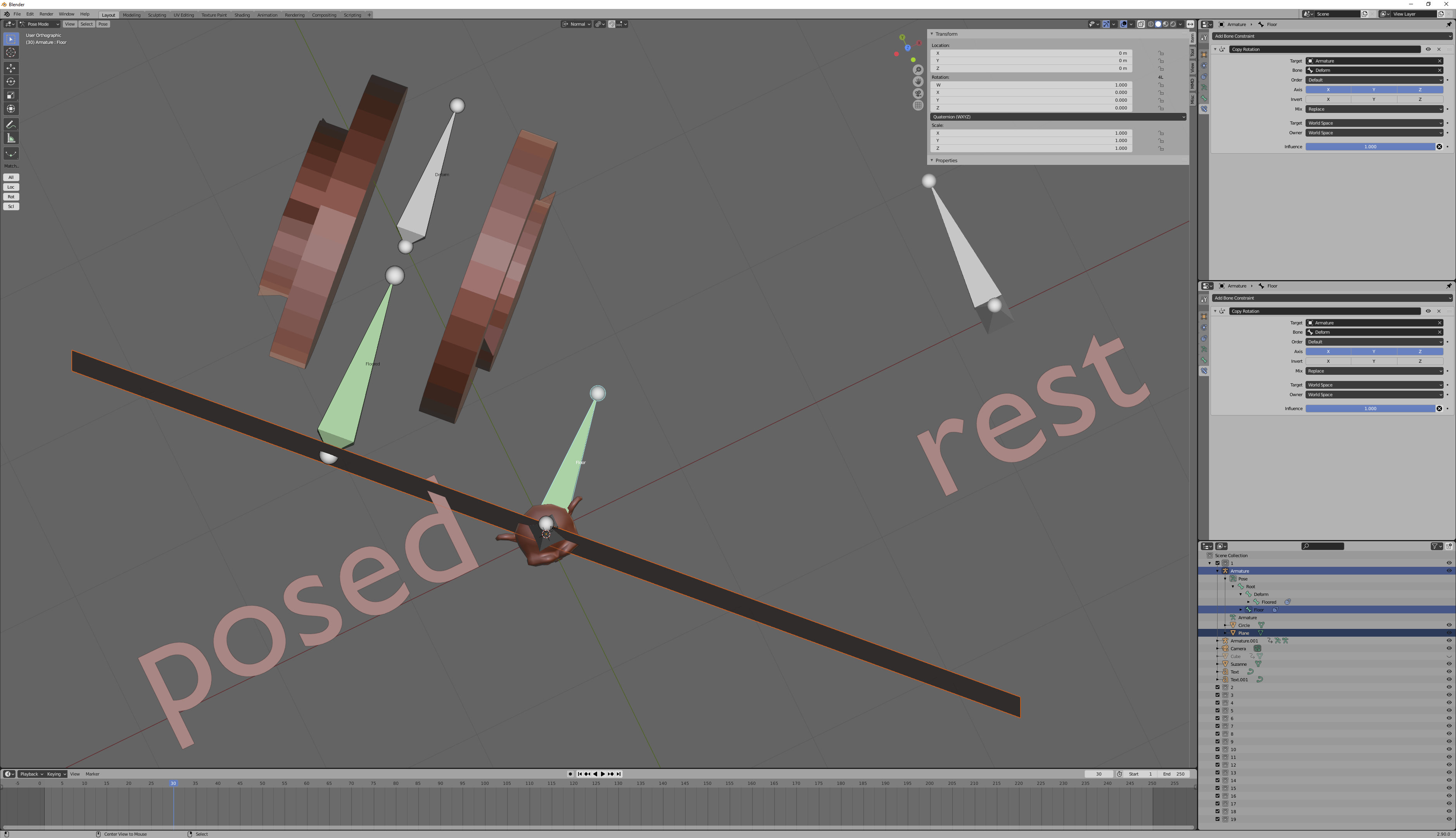
enter image description here

However, that's probably not what you want. Notice what happens when you rotate your deforming bone: the distance to the plane decreases, with rotation alone:
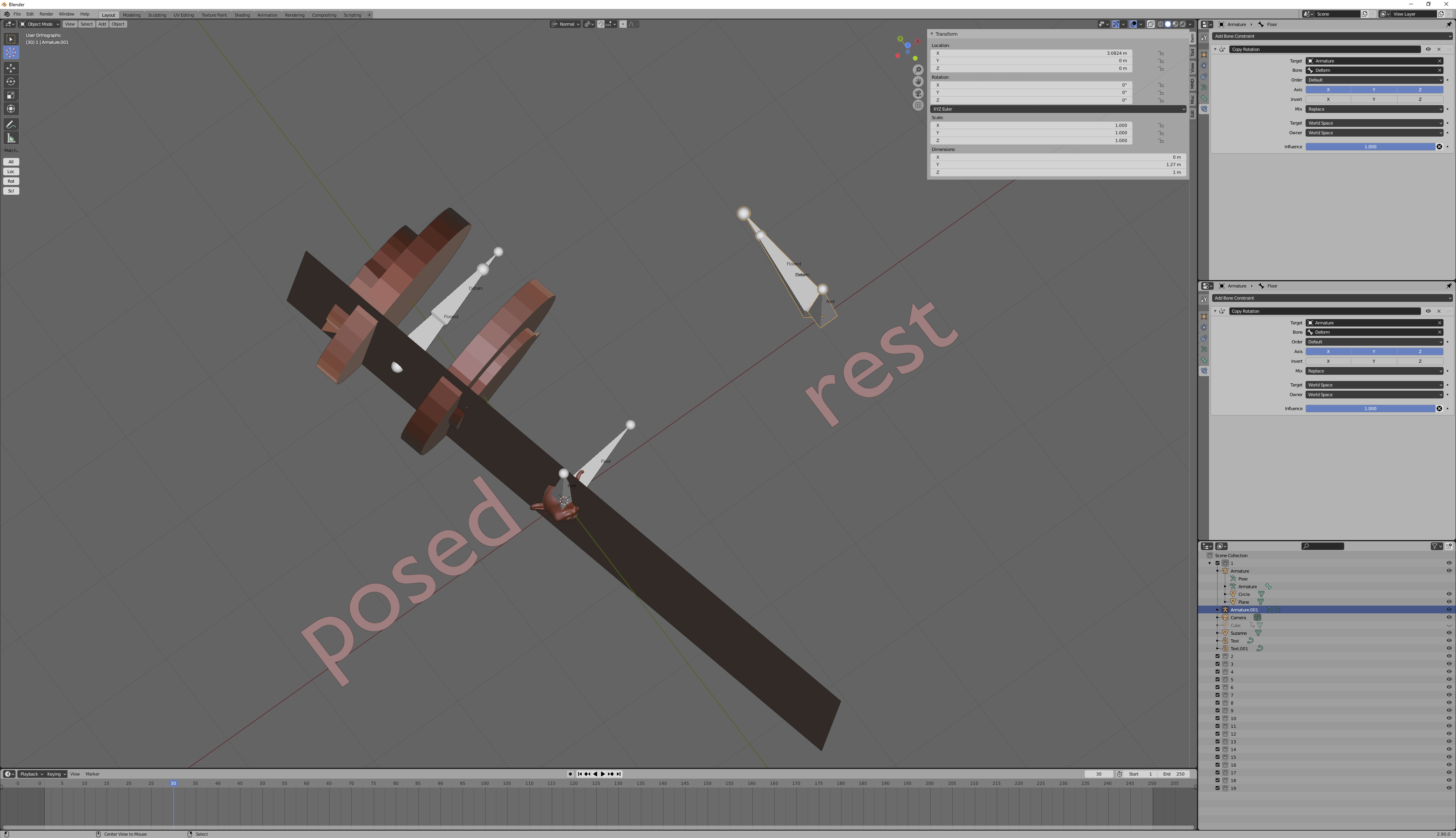
![enter image description here

And what it looks like you want is to have your tread magically know how far it's traveled. But rotation in place shouldn't rotate the tread, at least, not to that extent.

The bad news is, there's no way to do that with drivers and constraints, because how far it's traveled depends on the exact path it took. Did it take a straight line? Then the tread didn't have to rotate very much. Did it curve? Then the tread had to rotate more. But drivers and constraints don't know what happened on any frame other than their own.

If you want to make the tread know how far to travel, you have to define the path that it traveled, using some kind of curve object. Once you do that, you can figure out how far the tread needs to move by how far along that curve object you are. But you can't do it without that curve.

$\endgroup$
0
$\begingroup$

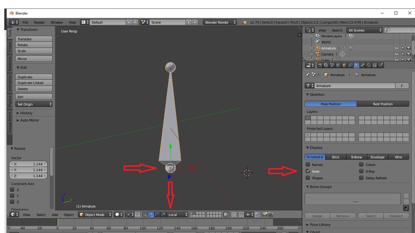
The exact Axis Orientation of the bone's Local axis can be found by toggling "ON" Axis under the bones Objectdata properties tab and switching transform orientation to Local axis.

Once the axis orientation is known, the correct axis can be selected to match the direction of vehicle motion and the wheel driver.

enter image description here

$\endgroup$
1
  • $\begingroup$ I do know the axis this isn't the issue for me $\endgroup$
    – Motcho
    Commented Sep 29, 2020 at 9:47

You must log in to answer this question.

Not the answer you're looking for? Browse other questions tagged .