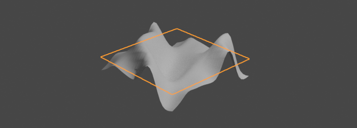
I have a plane in blender with a image texture node, connected to a RGB to black and white node connected to a multiplier before being connected to the displacement of the Material Output node. There appears to be some shadowing on the plane but it is only this that changes when I change the multiplier, the plane while viewed from the side rendered is still totally flat. Do I need to bake this in some way? Or have I totally misunderstood how displacement textures are supposed to work?
-
$\begingroup$ This explains why I just discovered that a displacement map loaded into an image texture node connected to the displacement input of a Material Output node does not seem to need extra mesh data (as would be excpeted ) it is in fact just a bump map. $\endgroup$– user2052727Commented Aug 12, 2014 at 2:06
3 Answers
Change the displacement type found in the Properties window under Object Data from (the default) Bump to True.
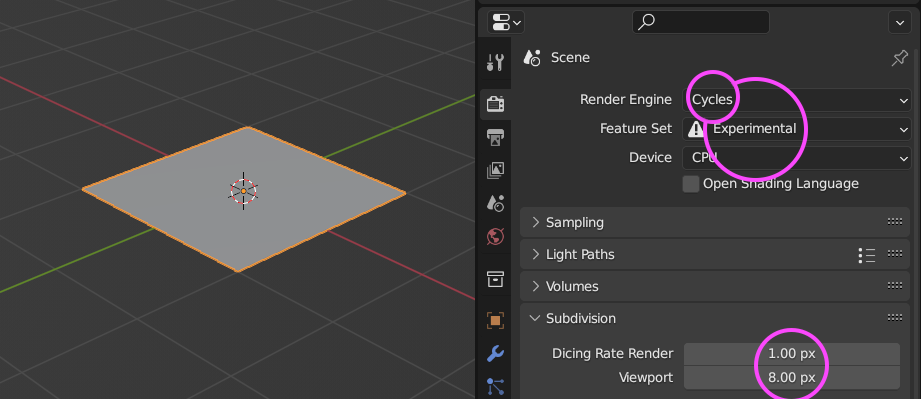
Note that this is an experimental feature and you must change the feature set from Supported to Experimental in Properties > Render Settings > Render.
True Displacement: Mesh vertices will be displaced before rendering, modifying the actual mesh. This gives the best quality results, if the mesh is finely subdivided. As a result this method is also the most memory intensive.
Bump Mapping: When executing the surface shader, a modified surface normal is used instead of the true normal. This is a quick alternative to true displacement, but only an approximation. Surface silhouettes will not be accurate and there will be no self shadowing of the displacement.
-
$\begingroup$ Could you please add a summery of the web page to your answer? If the site goes down, so does the answer. $\endgroup$– CharlesLCommented Jul 8, 2013 at 19:10
-
1$\begingroup$ @CharlesL, the link wasn't the answer, it just provided descriptions of the settings. But now included per your request. ;) $\endgroup$– AldrikCommented Jul 8, 2013 at 19:29
-
$\begingroup$ In Houdini, you can apply a displacement map that will do true displacement at render time, but doesn't require you to subdivide the mesh. Is this possible in Blender? $\endgroup$– JustinCommented Dec 20, 2013 at 4:26
-
1$\begingroup$ Where is the
Use Subdivisioncheckbox? And to make the subdiv modifier visible only at render time, do you just unclick the modifier's eyeball button, and make sure its camera button is clicked? $\endgroup$– JustinCommented Nov 12, 2015 at 16:49 -
1$\begingroup$ I would love if you could add some images to the answer, as following these steps doesn't give me the expected result (no displacement, or if I click "use subdivision" the faces of the mesh just separate or become solid color) $\endgroup$ Commented Apr 10, 2016 at 3:26
By default, using the 'Displacement' plug in the Node Editor does not truly displace the mesh, but "bump maps" it instead, which essentially means that it approximates the appearance of displacement without actually displacing it. In order to actually displace the mesh, you are going to have to use a different techique.
Although there are a variety of ways to do this, the standard way to displace a mesh, instead of using node 'Displacement', is to use the Displace modifier. To apply your node setup to the Displace modifer, choose a texture in the modifier panel, then select that texture and edit using the Node Editor.
-
$\begingroup$ Thanks for the info, I've tried this now and the displacement just moves my whole plane, what am I doing wrong now? $\endgroup$ Commented Jul 9, 2013 at 14:41
-
2$\begingroup$ @LeoSutton You need to use a simple subdivision surface modifier first. Displace only acts on vertices, so you need to use subdivision to give your plane more vertices for it to act on. $\endgroup$– GwenCommented Jul 9, 2013 at 14:56
Time for update ... True Displacement (called also micro-displacement) ... you make it work in three steps ...
1. Render Engine
... is still available for Cycles render engine and still under Experimental Feature Set ... Dicing Rate specify details in pixels.
2. Modifier
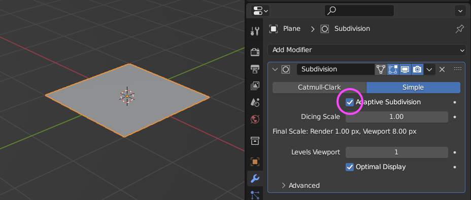
Add Subdivision Surface modifier and enable Adaptive Subdivision this feature is available (appears) only for modifier stacked as last (if there is more modifiers).
3. Material
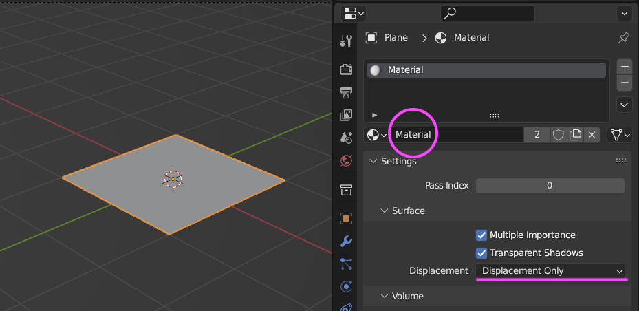
Under Material Properties > Settings > Surface switch from Bump to Displacement ...
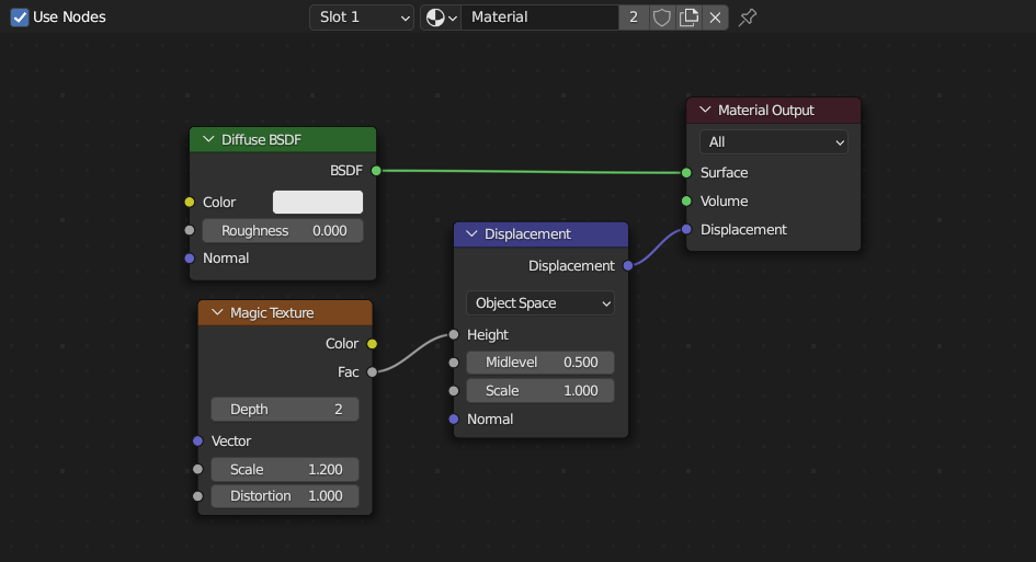
... and under Shader Editor > Add > Vector > Displacement node ... for input socket use your height map or procedural texture ... output socket plug into Material Output > Displacement socket.

