11
$\begingroup$

I have some Fragmentarium code that I would like to convert so it will work in Blender anyone have any ideas how I can do this?

The code is below:

#include "Progressive2D.frag"

#group Spiral
uniform int StripesNum; slider[1,10,100]
uniform int StripesAng; slider[-180,45,180]
uniform float StripesThinkness; slider[0,0.5,1]
uniform float CenterHole; slider[0,0.125,1]
uniform float OuterHole; slider[0,0.825,1]

const float pi = 3.141592653589793;

vec2 cLog(vec2 z)
{
return vec2(log(length(z)), atan(z.y, z.x));
}

vec3 color(vec2 p)
{
float t = radians(float(StripesAng));
float c = cos(t);
float s = sin(t);
mat2 m = mat2(c, -s, s, c);
vec2 q = m * cLog(p);
return vec3(float
( mod(float(StripesNum) * q.y / (sqrt(2.0) * pi), 1.0) < StripesThinkness
|| length(p) < CenterHole
|| length(p) > OuterHole
));

}

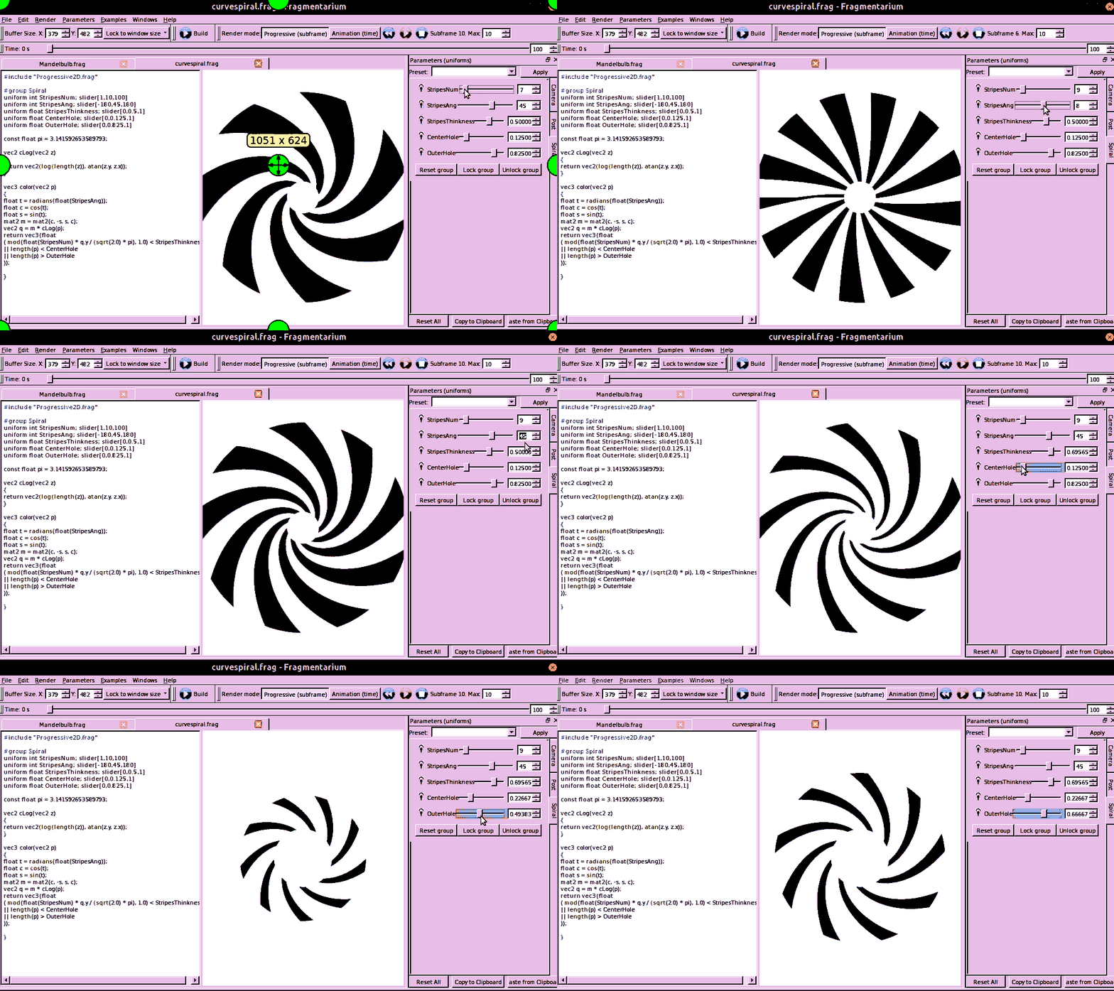
Here's the animation of the code working in Fragmentarium animation of the code working in Fragmentarium
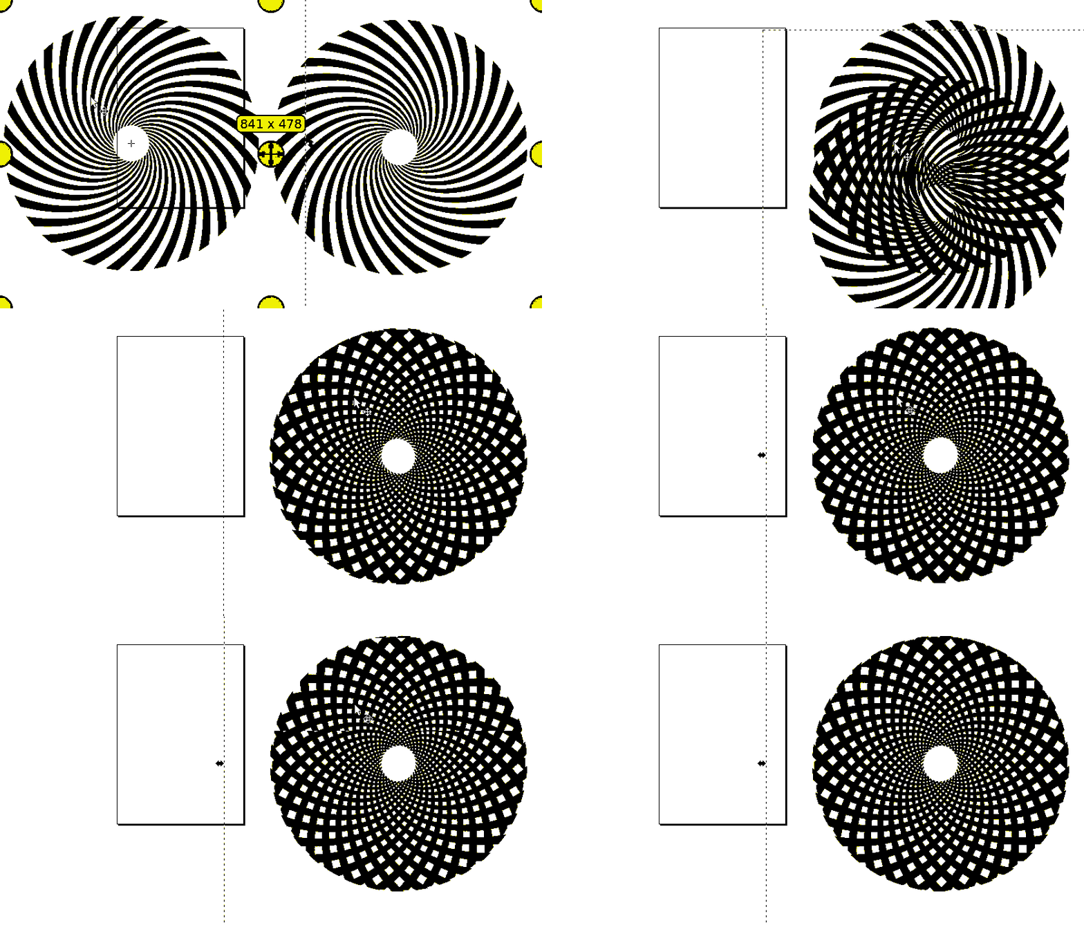
Here's the animation of moire patterns, I'm trying to recreate this in Blender so I can animate multiple copies of spirals turning at different rates (along with using sliders to adjust variables) to produce different moire patterns. moire patterns
Note: // Progressive2D.frag This is a utlity / include for the program to set up anti-aliased 2D rendering. Progressive2D.frag code location

$\endgroup$
3
  • $\begingroup$ Please use the built-in uploader to add any images or gifs to posts. See: meta.stackexchange.com/questions/75491/… $\endgroup$ Commented Jul 8, 2018 at 15:46
  • $\begingroup$ @RayMairlot I added new links because the animation files are 4.0mb and 6.6MB (the limit is 2.0Mb) I'll see if I can make them smaller $\endgroup$
    – Rick T
    Commented Jul 8, 2018 at 15:55
  • $\begingroup$ Added animation to question directly after using gifsicle to shrink the file size $\endgroup$
    – Rick T
    Commented Jul 15, 2018 at 18:24

1 Answer 1

23
$\begingroup$

Fragment Shader Solution

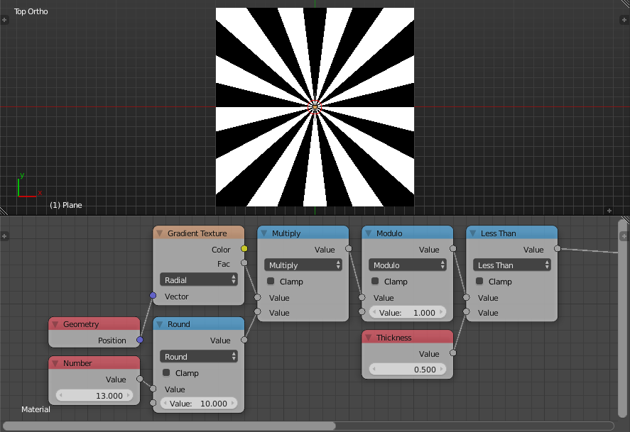
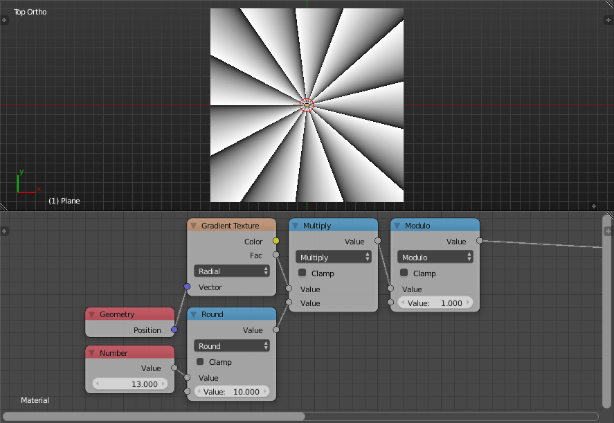
If we multiply the normalized polar angle by some number representing the number of strips and take its modulo with 1, it will give us a number of sub-normalized polar angle spaces.

Modulo

If I get the fragment that is less than some scalar ranging between zero and one representing the thickness, we will get sharp strips.

Less Than

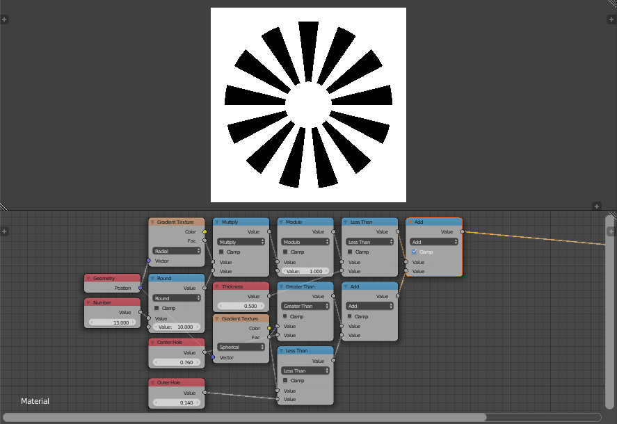
If I get the fragment that is less that some value representing one minus center hole radius and the fragments that is larger than some value representing one minus outer hole radius. And take both values and add them to the strips we get sharp hollow strips.

Holes

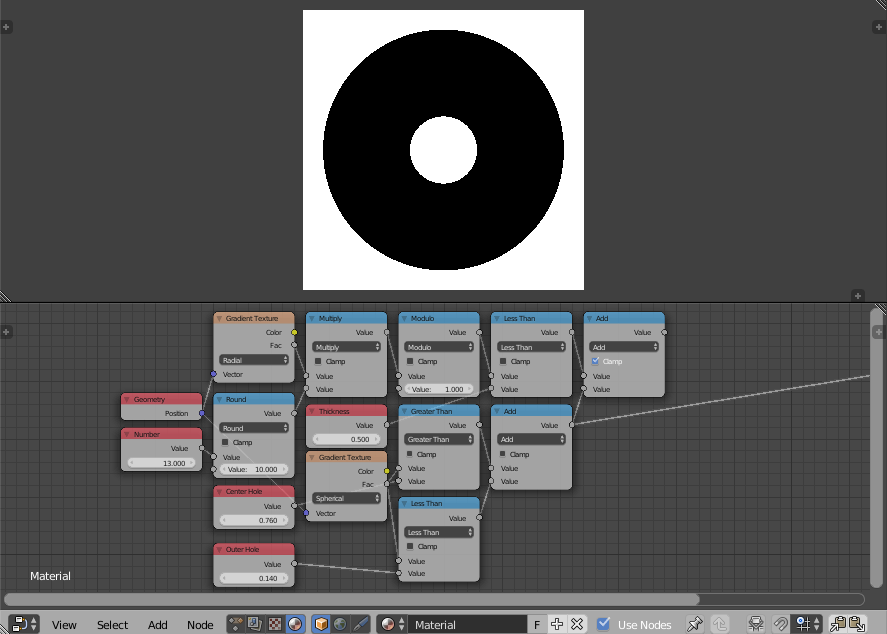
To better understand the previous step, notice that the addition of both values gives a mask as follows:

Mask

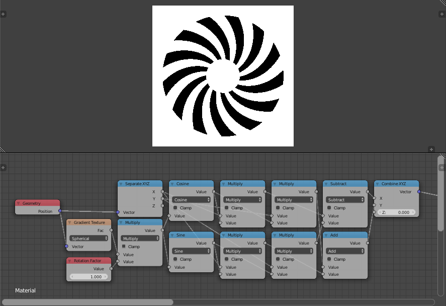
Now, notice that the final result is deformed somehow, this deformation is resulted from rotating the space such that the amount of rotation of each fragment is proportional to its distance from the center. The equation of rotation is as follows:

$$ \begin{aligned} x^\prime &= x\cos \theta -y\sin \theta \\ y^\prime &= x\sin \theta +y\cos \theta \end{aligned} $$

Where $\theta$ is the amount of rotation which is proportional to the distance to the center. So, by rotating the space using the previous equations, we get:

Rotation

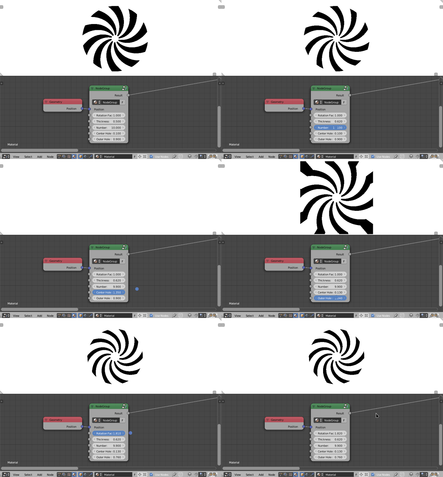
Notice, that by rotating the space, I mean the space used to compute the strips. So, from all of this, we get the shader that you were hopping to get:

Final

Animation Nodes Solution

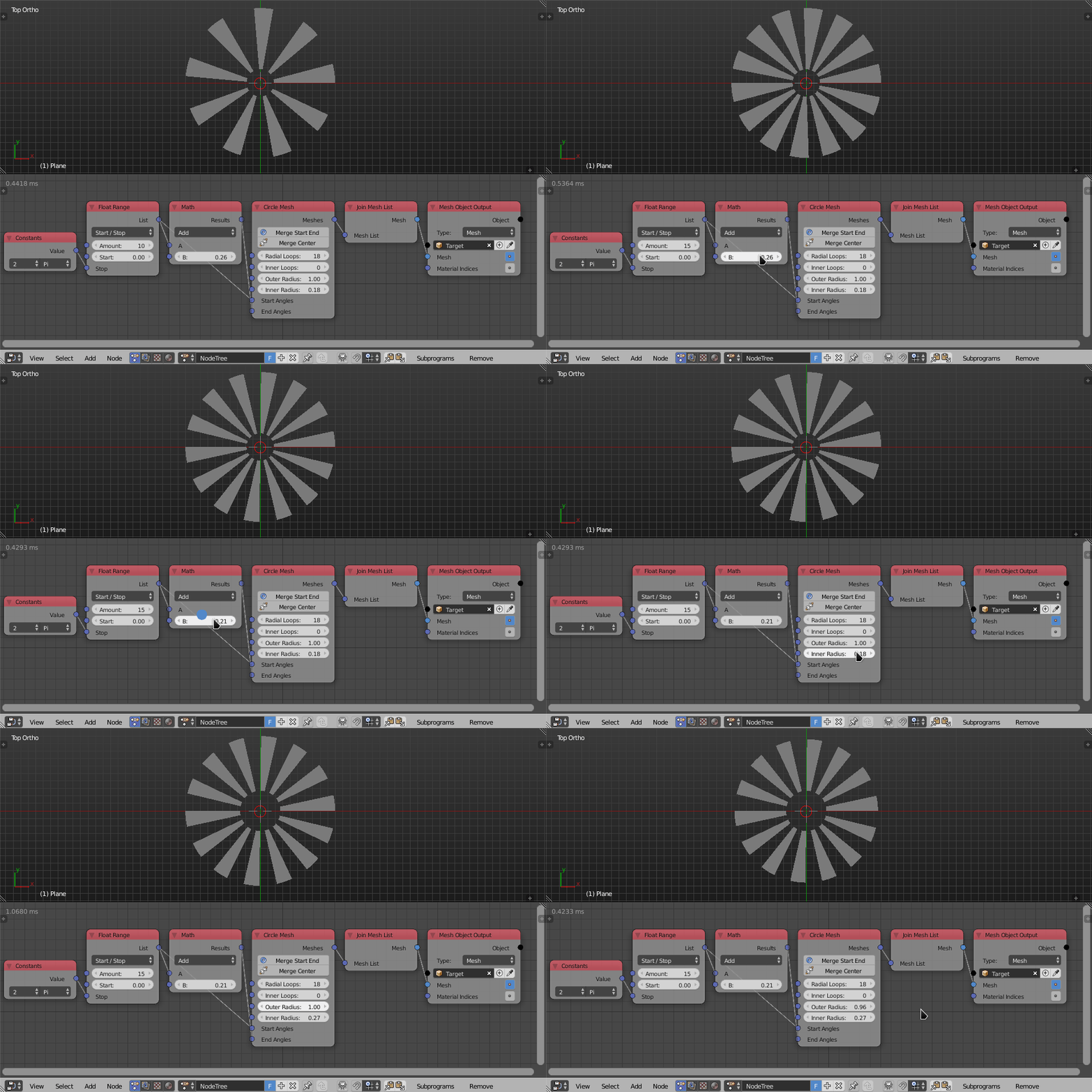
If you want the output shape as a mesh, then Animation Nodes can be used. The circle node can be used to easily make sharp strips, this can be done using such a simple node tree:

Circle Node

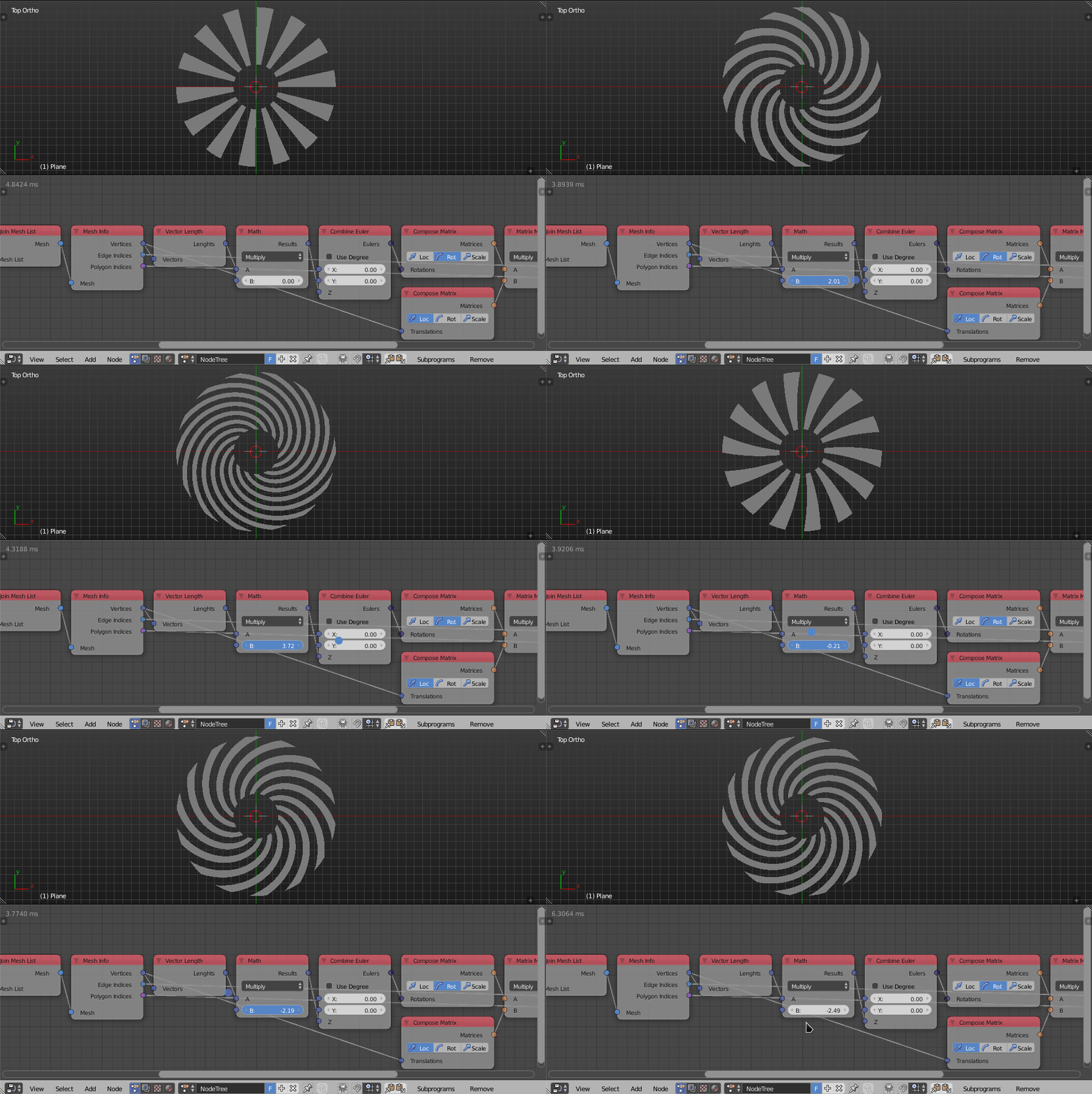
Same as before, we should rotate the vertices of the mesh such that the rotation factor is proportional to the distance to the center of the space. There are multiple ways to do this in Animation Nodes, one way is to use matrices just like the code above uses, another is to use the equations we used above, a third is to use the high level nodes in AN like falloffs and such. In this answer, I shall I use matrices.

Simply compose a matrix composed of the mesh vertices and multiply it by a z-rotation matrix its value is proportional to the distance to the center. Then extract the new vertices locations and compose a mesh from them. Also, make sure to increase the amount of inner loops in the circle node, ensuring there is enough geometry to create the desired effect.

Rotation Matrix

This gives the final result:

Final AN Result

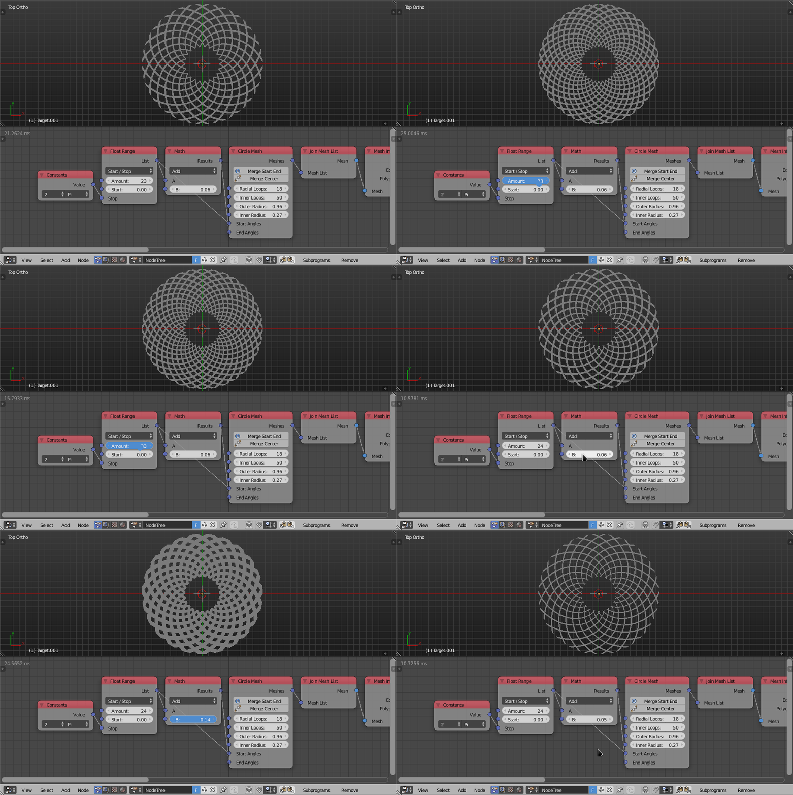
By duplicating the mesh and mirroring it, we get the pattern you are after. Same goes for the fragment solution.

Pattern

$\endgroup$

You must log in to answer this question.

Not the answer you're looking for? Browse other questions tagged .