Rigid Body Constraints
Introduction
Constraints (also known as joints) for rigid bodies connect two rigid bodies.
The physics constraints available in the non-game modes are meant to be attached to an Empty object. The constraint then has fields which can be pointed at the two physics-enabled object which will be bound by the constraint. The Empty object provides a location and axis for the constraint distinct from the two constrained objects. The location of the entity hosting the physics constraint marks a location and set of axes on each of the two constrained objects. These two anchor points are calculated at the beginning of the animation and their position and orientation remain fixed in the local coordinate system of the object for the duration of the animation. The objects can move far from the constraint object, but the constraint anchor moves with the object. If this feature seems limiting, consider using multiple objects with a non-physics Child-of constraint and animate the relative location of the child.
Connect
The quickest way to constrain two objects is to select both and click the Connect button in the Physics tab of the Tool Shelf. This creates a new Empty object (named “Constraint”) with a physics constraint already attached and pointing at the two selected objects.
Physics Tab
Also you can create Rigid Body Constraint on of the two constrained objects with Rigid Body Constraint button of the Physics tab in the Properties editor. This constraint is dependent on the object location and rotation on which it was created. This way, there are no Empty object created for the constraint. The role of the Empty object is put on this object. The constrained object can be then set as Passive type for better driving the constrain.
Additional parameters appear in the Rigid Body Constraint panel of the Physics tab in the Properties editor for the selected Empty object or the one of the two constrained objects with the created constraint.
Common Options
Rigid Body Constraint panel.
Enabled
Specifies whether the constraint is active during the simulation.
Disable Collisions
Allows constrained objects to pass through one another.
Object 1
First object to be constrained.
Object 2
Second object to be constrained.
Breakable
Allows constraint to break during simulation. Disabled for the Motor constraint. This can be used to simulate destruction.
Threshold
Impulse strength that needs to be reached before constraint breaks.
Override Iterations
Allows to make constraints stronger (more iterations) or weaker (less iterations) than specified in the rigid body world.
Iterations
Number of constraint solver iterations made per simulation step for this constraint.
Limits
By using limits you can constrain objects even more by specifying a translation/rotation range on/around respectively axis (see below for each one individually). To lock one axis, set both limits to 0.
Fixed
Panel: Physics ‣ Rigid Body Constraint
Type: Fixed
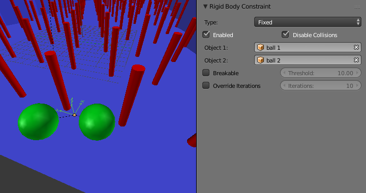
Options available to a Fixed constraint.
This constraint cause the two objects to move as one. Since the physics system does have a tiny bit of slop in it, the objects do not move as rigidly as they would if they were part of the same mesh.
Point
Panel: Physics ‣ Rigid Body Constraint
Type: Point
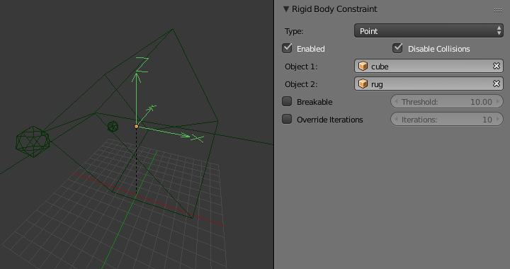
Options available to a Point constraint.
The objects are linked by a point bearing allowing any kind of rotation around the location of the constraint object, but no relative translation is permitted. The physics engine will do its best to make sure that the two points designated by the constraint object on the two constrained objects are coincident.
Hinge
Panel: Physics ‣ Rigid Body Constraint
Type: Hinge
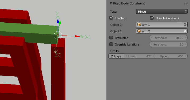
Options available to a Hinge constraint.
The hinge permits 1 degree of freedom between two objects. Translation is completely constrained. Rotation is permitted about the Z axis of the object hosting the Physics constraint (usually an Empty, distinct from the two objects that are being linked). Adjusting the position and rotation of the object hosting the constraint allows you to control the anchor and axis of the hinge.
The Hinge is the only 1-axis rotational constraint that uses the Z axis instead of the X axis. If something is wrong with your hinge, check your other constraints to see if this might be the problem.
Options
Limits
Z Angle
Enables/disables limit rotation around Z axis.
Lower
Lower limit of Z axis rotation.
Upper
Upper limit of Z axis rotation.
Slider
Panel: Physics ‣ Rigid Body Constraint
Type: Slider
The Slider constraint allows relative translation along the X axis of the constraint object, but permits no relative rotation, or relative translation along other axes.
Options
Limits
X Axis
Enables/disables limit translation around X axis.
Lower
Lower limit of X axis translation.
Upper
Upper limit of X axis translation.
Piston
Panel: Physics ‣ Rigid Body Constraint
Type: Piston
A piston permits translation along the X axis of the constraint object. It also allows rotation around the X axis of the constraint object. It is like a combination of the freedoms of a slider with the freedoms of a hinge (neither of which is very free alone).
Options
Limits
X Axis
Enables/disables limit translation around X axis.
Lower
Lower limit of X axis translation.
Upper
Upper limit of X axis translation.
X Angle
Enables/disables limit rotation around X axis.
Lower
Lower limit of X axis rotation.
Upper
Upper limit of X axis rotation.
Generic
Panel: Physics ‣ Rigid Body Constraint
Type: Generic
The generic constraint has a lot of available parameters.
The X, Y, and Z axis constraints can be used to limit the amount of translation between the objects. Clamping the min/max to zero has the same effect as the Point constraint.
Clamping the relative rotation to zero keeps the objects in alignment. Combining an absolute rotation and translation clamp would behave much like the Fixed constraint.
Using a non-zero spread on any parameter allows it to rattle around in that range throughout the course of the simulation.
Options
Limits
X Axis/Y Axis/Z axis
Enables/disables limit translation on X, Y or Z axis respectively.
Lower
Lower limit of translation for X, Y or Z axis respectively.
Upper
Upper limit of translation for X, Y or Z axis respectively.
X Angle/Y Angle/Z Angle
Enables/disables limit rotation around X, Y or Z axis respectively.
Lower
Lower limit of rotation for X, Y or Z axis respectively.
Upper
Upper limit of rotation for X, Y or Z axis respectively.
Generic Spring
Panel: Physics ‣ Rigid Body Constraint
Type: Generic Spring
Options available to a Generic Spring constraint.
The generic spring constraint adds some spring parameters for the X/Y/Z axes to all the options available on the Generic constraint. Using the spring alone allows the objects to bounce around as if attached with a spring anchored at the constraint object. This is usually a little too much freedom, so most applications will benefit from enabling translation or rotation constraints.
If the damping on the springs is set to 1, then the spring forces are prevented from realigning the anchor points, leading to strange behavior. If your springs are acting weird, check the damping.
Options
Limits
X/Y/Z Axis
Enables/disables limit translation on X, Y or Z axis respectively.
Lower
Lower limit of translation for X, Y or Z axis respectively.
Upper
Upper limit of translation for X, Y or Z axis respectively.
X/Y/Z Angle
Enables/disables limit rotation around the X, Y or Z axis respectively.
Lower
Lower limit of rotation for X, Y or Z axis respectively.
Upper
Upper limit of rotation for X, Y or Z axis respectively.
Springs
X/Y/Z Axis
Enables/disables springs translation on X, Y or Z axis respectively.
Stiffness
Spring Stiffness of the translation on X, Y or Z axis respectively. Specifies how “bendy” the spring is.
Damping
Spring Damping of the translation on X, Y or Z axis respectively. Amount of damping the spring has.
X/Y/Z Angle
Enables/disables springs rotation around the X, Y or Z axis respectively.
Stiffness
Spring Stiffness of the rotation around the X, Y or Z axis respectively. Specifies how “bendy” the spring is.
Damping
Spring Damping of the rotation around the X, Y or Z axis respectively. Amount of damping the spring has.
Motor
Panel: Physics ‣ Rigid Body Constraint
Type: Motor
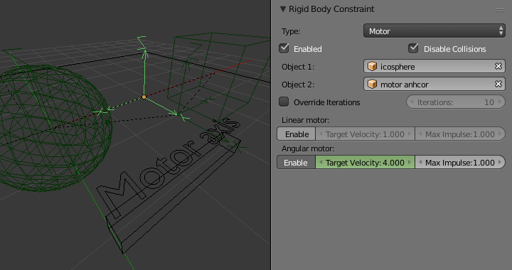
Options available to a Motor constraint.
The motor constraint causes translation and/or rotation between two entities. It can drive two objects apart or together. It can drive simple rotation, or rotation and translation (although it will not be constrained like a screw since the translation can be blocked by other physics without preventing rotation).
The rotation axis is the X axis of the object hosting the constraint. This is in contrast with the Hinge which uses the Z axis. Since the Motor is vulnerable to confusing perturbations without a matching Hinge constraint, special care must be taken to align the axes. Without proper alignment, the motor will appear to have no effect (because the hinge is preventing the motion of the motor).
Options
Linear motor/Angular motor
Enable
Enable linear or angular motor respectively.
Target Velocity
Target linear or angular motor velocity respectively.
Max Impulse
Maximum linear or angular motor impulse respectively.

