I am trying to simulate with the piston constraint by putting the rigid body piston into another rigid body shell such that they can work as a piston mechanism. However, the piston inside the shell is vibrating and the shell doesn't work as which appear as there is a shell cavity. The piston just merely treat the expected hollow part as a solid and unwanted collision happened. Thus, the simulation doesn't work as expected. How can I solve this situation?
1 Answer
Unexpected results from Rigid Body simulations are often the result of incorrect geometry (such as wrongly oriented normals) or bad collision parameters. It's difficult to say what your specific problem is without seeing your actual set-up but here's a few things to try.
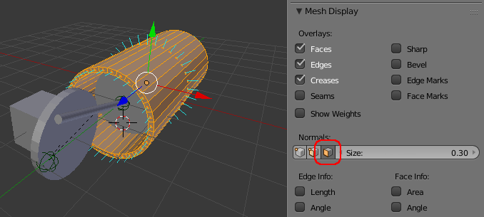
Firstly, check the normals of your meshes - look out for any meshes where the normal is not pointing 'out' of the surface. Bad normals can be the result of negatively scaled meshes. To check the normals you can enable the Display Face Normals as Lines option in the Mesh Display properties in the properties panel to the right of the 3D View. If you need to then you can tell Blender to recalculate the normals by selecting all while in Edit mode and then hitting Ctrl+N.
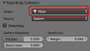
The next thing to check is the Rigid Body Collisions Shape in the Physics panel. This is fine set to 'Convex Hull' if the mesh does not have any inward curving faces but your cylinder 'shell' will need to be set to 'Mesh' to ensure the hole through the centre is treated as not solid.
For some simulations you can simply rely on the interactions of the meshes themselves. However, it's often useful to give the simulation a helping hand by adding Rigid Body Constraints. The constraints allow you to dictate how two objects interaction - usually also disabling any collision between those two objects. Typically a constraint consists of an Empty that sits between the two objects, linking them together in some way. For 'directional' constraints (such as Hinge, Motor, Piston) the orientation of the Empty is significant and, confusingly, depends on the type of constraint!
- For a Hinge constraint the 'edge' of the hinge is in the local Z-axis of the Empty. It's useful to use a 'Single Arrow' style of empty and the 'arrow' should point in the direction of the hinge (think of the door frame up the side of a hinged door).
- For a Motor contraint, the rotational element of the force is applied around the local X-axis of the Empty. This has certainly caused confusion in the past since if you set up a Hinge and a Motor on the same objects (say an axle and a wheel) then the two empties must be oriented differently, otherwise no motion will occur. Similarly, the linear element of the force also works along the local X-axis.
- For a Piston constraint, the motion is constrained along the local X-axis of the Empty, similar to the Motor constraint.
The Hinge is the only one of these constraints which has an intuitive style of Empty that matches it's action - it would be useful to have Empty styles that matched the different directions - for example, if the Cone style were oriented along the X-axis rather than the Y-Axis then it woul be a useful style to 'point the way' of the Motor and Piston constraints!
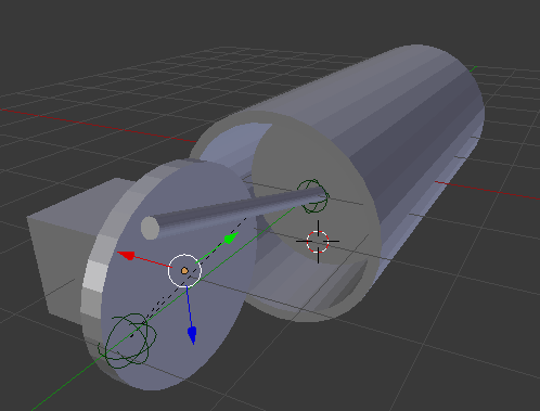
To demonstrate this in action I created the following quick scene.
It consists of a 'block' to anchor the wheel to, a 'wheel', a 'rod', the 'piston' and the 'cylinder', all positioned at their start locations. A Hinge constraint is positioned in the centre of the wheel (oriented with Z pointing in the direction of the presumed axle), along with a Motor constraint (oriented with X pointing along the axle so the action is around the axle). A Point constraint is positioned where the rod connects to the wheel. Another Point constraint is positioned where the rod connections to the piston. The piston lies within the cylinder - and the cylinder is set with it's Rigid Body Collision shape set to 'Mesh' (although you could use a Piston constraint for this instead, if preferred).
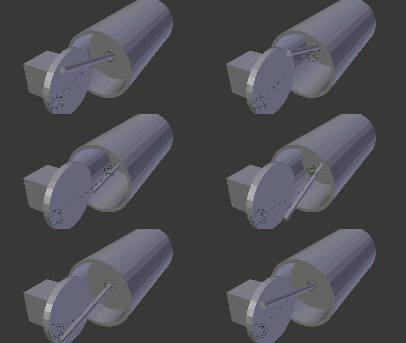
Running the animation produces the following results :


