Im struggling somewhat with geometry nodes to understand why some attributes work the way they do. In this video https://www.youtube.com/watch?v=nFtRnBErnmw&t=330s around minute 3:30 it shows how the capture attribute of position is going down to the center point of the geometry. Then pulling the value directly from the position node shows the position of the original mesh. What does running the position node through the capture attribute node do? Why when you mix them instead of moving the hexagons between the outer and center position it is scaling them? When I attach the viewer node to any of the position or store attribute I get an empty list in the spreadsheet screen.
2 Answers
Capture Attribute
This node is essential because field input nodes like the Position Node work in the context of the node they are connected to. (Official Blender documentation)
Without a Capture Attribute, the input node Position will return the position of each vertex/edge/face (depends on the context).
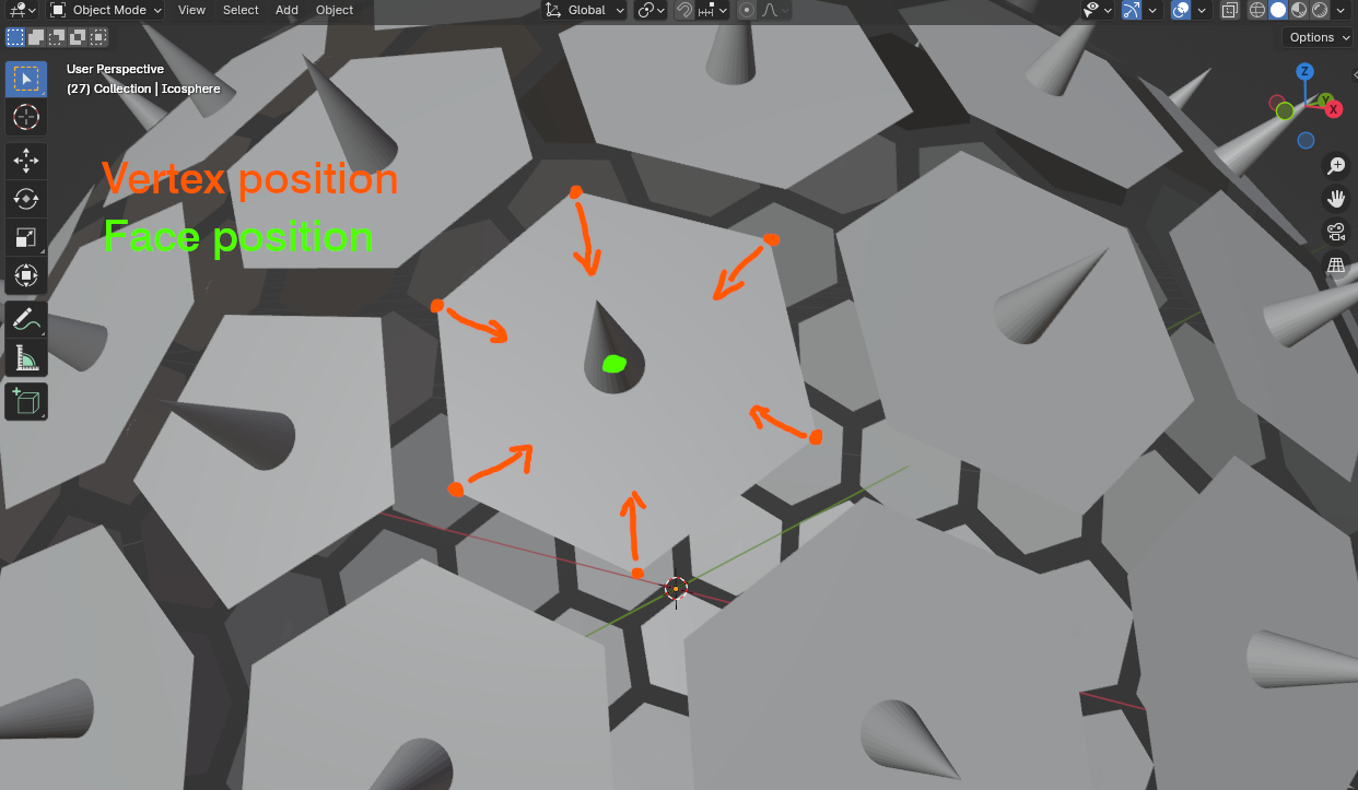
By passing the Position through a Capture Attribute set on Face, you are now getting the position of the face, which is the same for all 5 or 6 vertices of the face.
So, for each vertex, by mixing between the position of the vertex and the position of the face to which it belongs, you are attracting all 5 or 6 vertices to the center of the face. You are only playing between [position of vertices] and [position of face].
Here is a visualisation for one face, where face position is shown by cones.
So in your example, you are capturing the position of the face and using it on vertices.
Your questions
What does running the position node through the capture attribute node do ?
You are explicitly asking to get the Position from the point of view of a certain Domain (here, Face).
Why when you mix them instead of moving the hexagons between the outer and center position it is scaling them ?
You are not mixing between [vertex position] and [origin], but between [vertex position] and [face position]. You are only repositioning the vertices but you are correct, it is identical to scaling faces.
When I attach the viewer node to any of the position or store attribute I get an empty list in the spreadsheet screen.
You can set your Viewer to any Domain you want : face, vertex, ... Default is automatic and doesn't always give you what you are expecting.
-
1$\begingroup$ Thank you. This cleared up a good bit. When you explained that repositioning the vertices was what was being done with the set position that cleared up a lot. $\endgroup$ Commented Mar 29 at 2:12
(Using Blender 3.6.8)
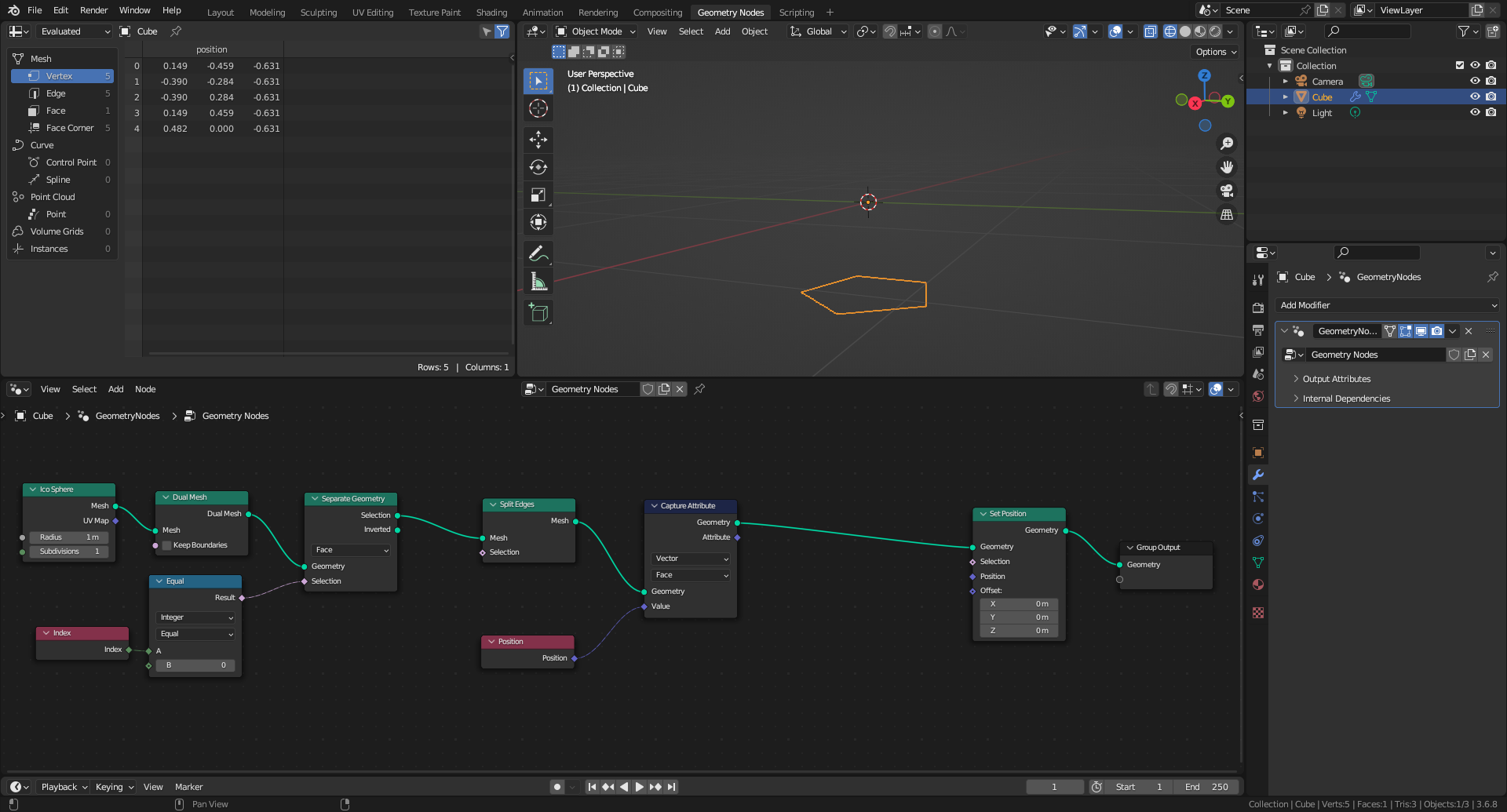
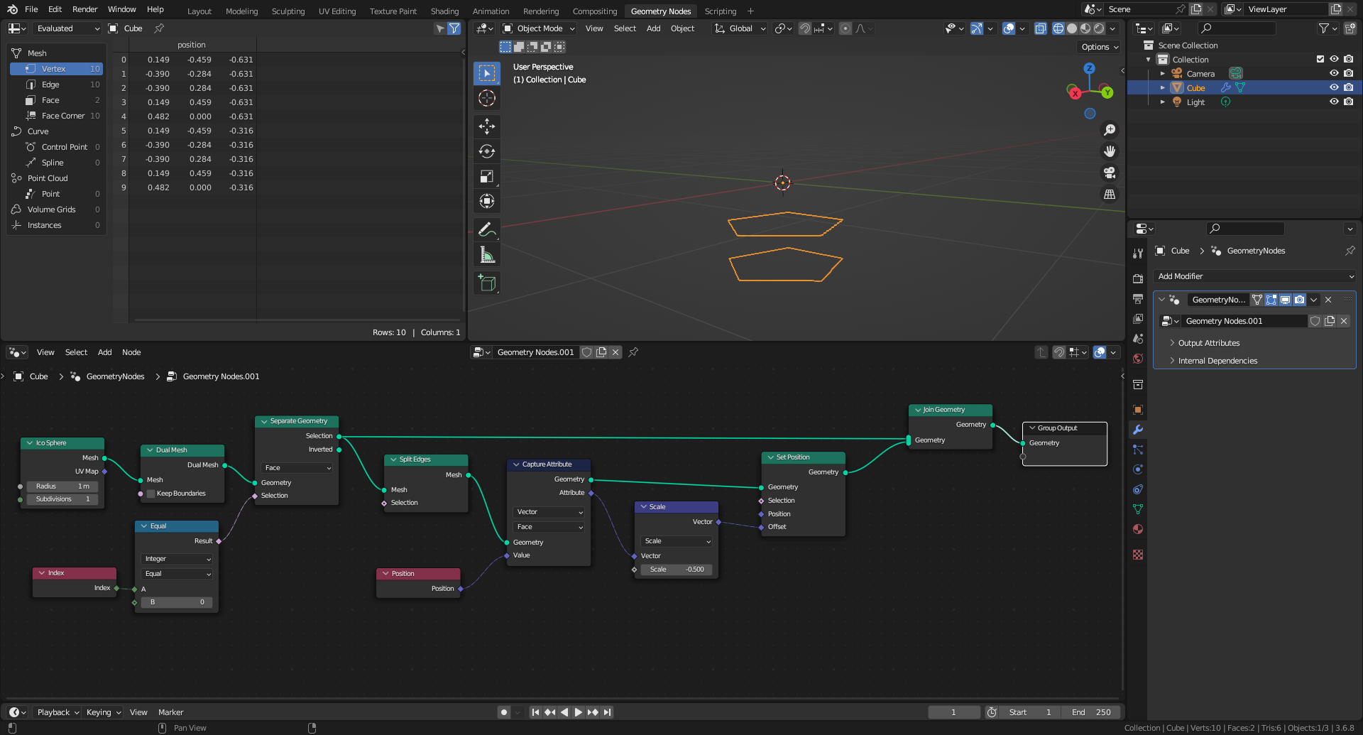
Following is a step by step explanation of what is going on in the referenced video, with a simplified geometry. In particular, using a Separate Geometry node, only the first face (of Index 0) is kept.
1. The Spreadsheet shows the position of the 5 vertices.
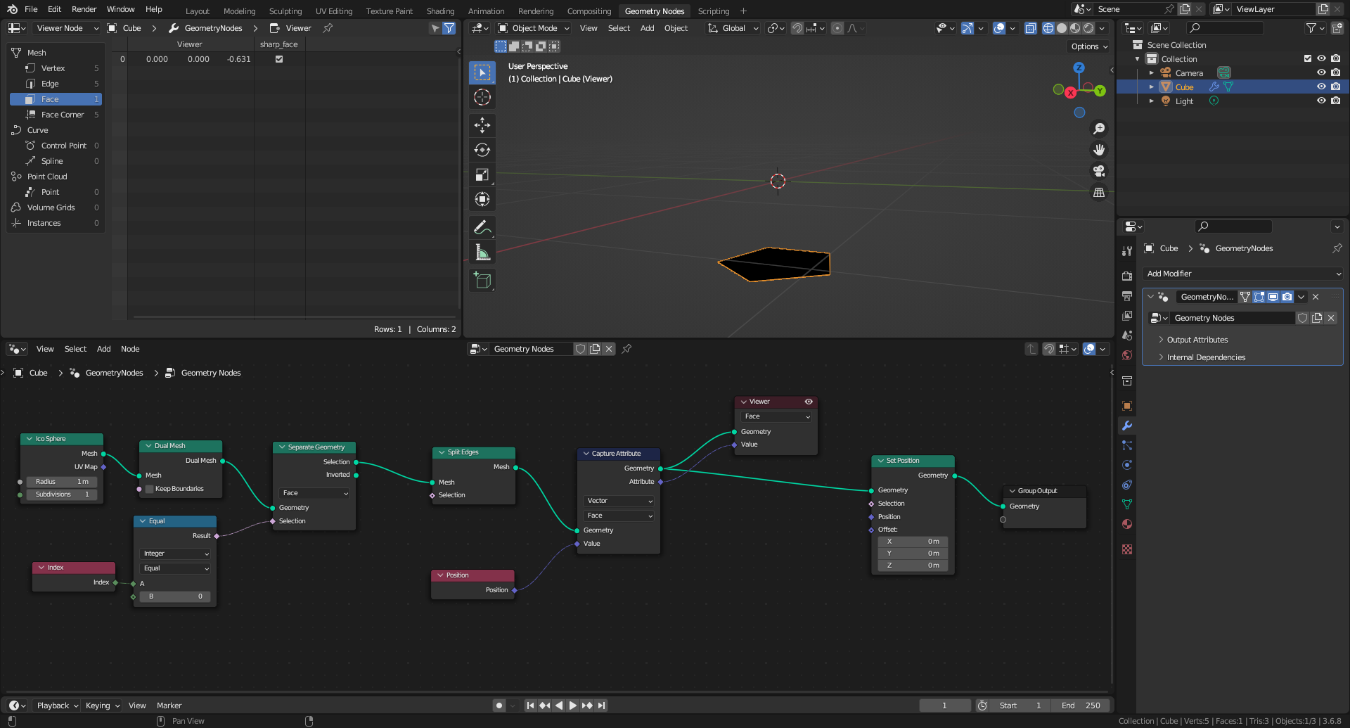
2. The Capture Attribute node set in Face domain is recovering the position of the face, i.e. its barycentre, the mean position of its 5 vertices. This value can be displayed in the Spreadsheet using a Viewer node, here conveniently set also in Face domain.
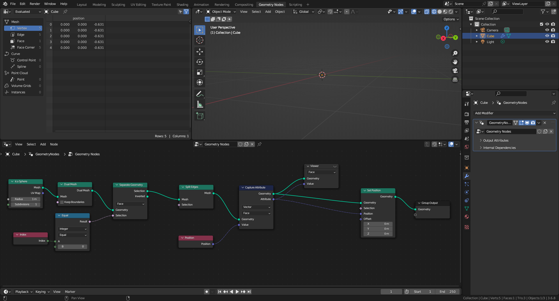
3. The Set Position node is modifying the vertices position, not the face position. So if the Attribute socket of the Capture Attribute node is connected to the Position socket of the Set Position node, the vertices position is set to the face position they belong. As a consequence, they all collapse at the face barycentre, as shown in the Spreadsheet, not at the object origin. The face is invisible, because its area is null.
4. (NB: instead of using a Mix node, the following graph is taking advantage of the Offset socket of the Set Position node). To move the face, the position of its vertices is shifted by the Set Position node. The shifting direction is defined as the vector going from the object origin (i.e. the origin of coordinates inside a Geometry Nodes modifier) to the face barycentre. The shifting amplitude is defined as a fraction of this vector, controlled by the Scale node (a Vector Math node). Both faces are joined together to be displayed in the Spreadsheet. The first 5 vertices are the unmodified ones. The last 5 vertices are the shifted ones. With this particular face, the shifting direction is -Z, simplifying the analysis.
-
$\begingroup$ Thank you, this explained a lot but was not as clear as the other answer. $\endgroup$ Commented Mar 29 at 2:10

