16
$\begingroup$

I know it's possible to do this in BI, but I need your help to do this in cycles.
For now, I have a setup to use an image sequence as volume but it only shows 1 slice/frame. I'm using generated texture coordinates for easy mapping (0-1 on each axis). The images are mapped on XY and I would like to use normalized frame# as Z coordinate to map the sequence as a volume.

starting setup

Images sequence can be found here (I'm using 16-bit TIF files of MRBrain in this exemple).

Any solution is welcome but try to keep it simple and user friendly :).

Final Edit:
I had a hard time choosing between Lemon's and PGmath's answers.
Lemon's is more user friendly and flexible, and uses the image sequence without any change inside blender.
PGmath's uses a 3rd party converter to make the sequence 1 single image, but allows GPU rendering.
Well, ImageMagick's command line is : "convert +append *.tif anim.tif" from the folder where the sequence is unzipped. Not so hard. That's why I accepted PGmath's answer.

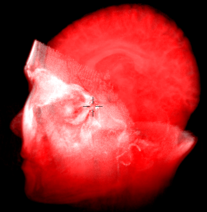
final volume

Now, i played with it, and here's the result.
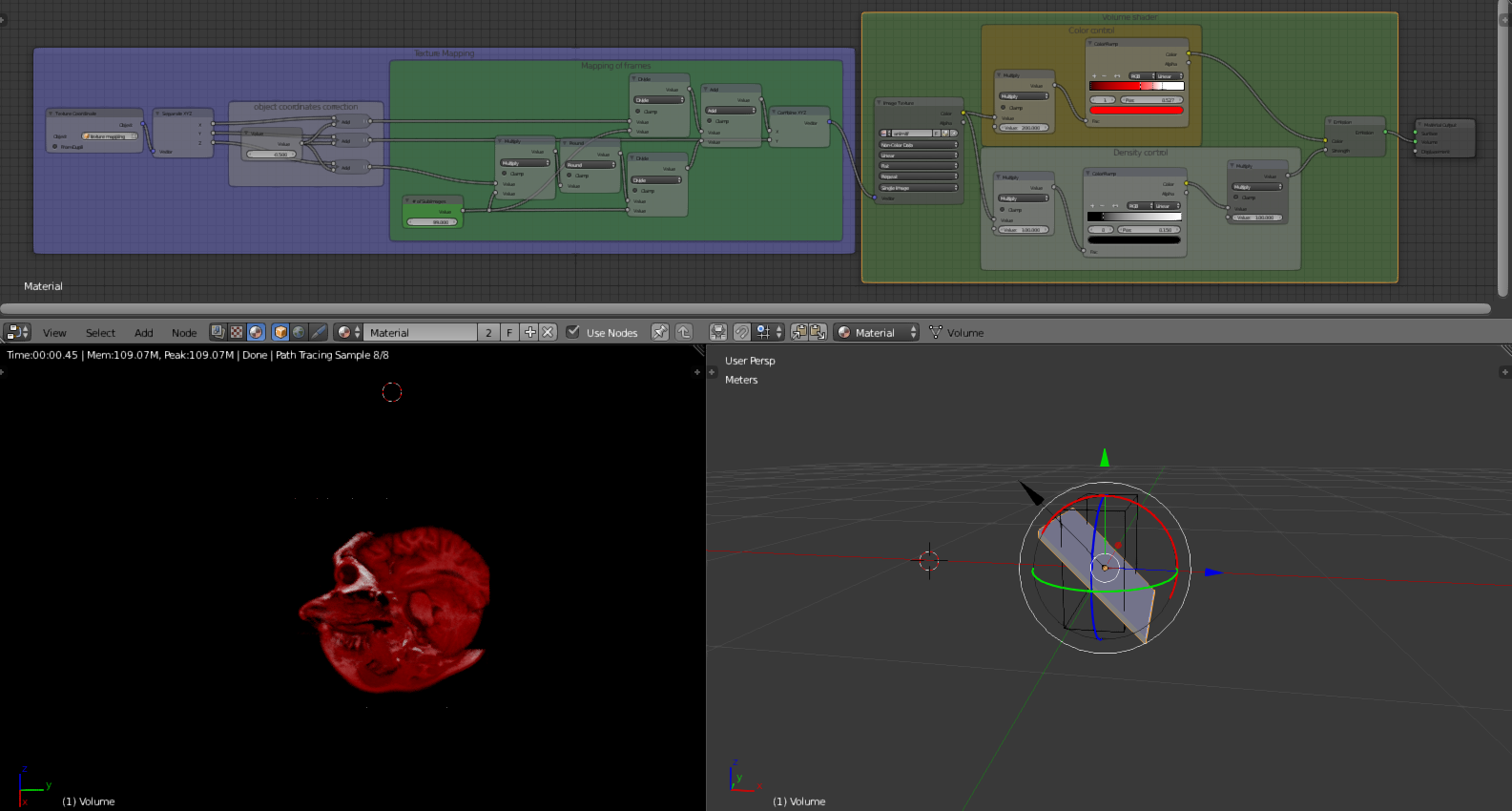
final blend
The "volume" object contains the volume shader (playing with the color ramp gives funny things) and the boolean modifiers (turn them off to see the complete volume, but reduce the final density multiplier for better view).
The "Slice Control" arrow empty controls the slice position/rotation.
The "Texture Mapping" object controls...the mapping, if it need some tunning (position, rotation, scale, and then tiling if necessary?).

$\endgroup$
13
  • $\begingroup$ The image node cannot show multiple frames at the same time. You would need to iterate the frame# over instances of the Image node. Maybe Animation Nodes addon would be more useful here? Perhaps it could be an image stack instead of a volume? $\endgroup$
    – 3pointedit
    Commented Sep 1, 2016 at 11:03
  • $\begingroup$ @3pointedit It has to be a volume, but no problem if you find an answer with animation nodes. But how to import 100 images and keep things simple without using image sequence node? $\endgroup$
    – Bithur
    Commented Sep 1, 2016 at 11:15
  • $\begingroup$ Scripting and make 100 slices and 100 corresponding materials... but not sure this is "simple and user friendly"... $\endgroup$
    – lemon
    Commented Sep 1, 2016 at 11:32
  • $\begingroup$ @lemon mapping 100 images on Z manually in 1 volume material could be done too, but the problem is to keep it simple and user friendly. $\endgroup$
    – Bithur
    Commented Sep 1, 2016 at 11:48
  • $\begingroup$ How is the image sequence stored? Is it a single "strip"-style image (I.e. all sub images strung together into one image), or something like a gif? (Sorry I am not too famiar with tiffs and I am on my phone atm so I can't open the gzip.) For the former case I have a fairly simple solution. $\endgroup$
    – PGmath
    Commented Sep 1, 2016 at 13:39

3 Answers 3

15
$\begingroup$

If you don't want to use OSL as in lemon's answer I have created a method to do this using only Cycles nodes. (Remember OSL isn't supported on GPU.) The downside to my method is that it requires the image sequence be entirely contained in one image, strip-style (like below).

enter image description here

I found an open source tool called spritetool* that seems to work pretty well for combining large amounts of images into one strip.

It seems a little clunky having such a big image, especially considering the resolution of the files you are dealing with. But it's the best I can come up with right now since the Image Texture node is not very flexible with image sequences.


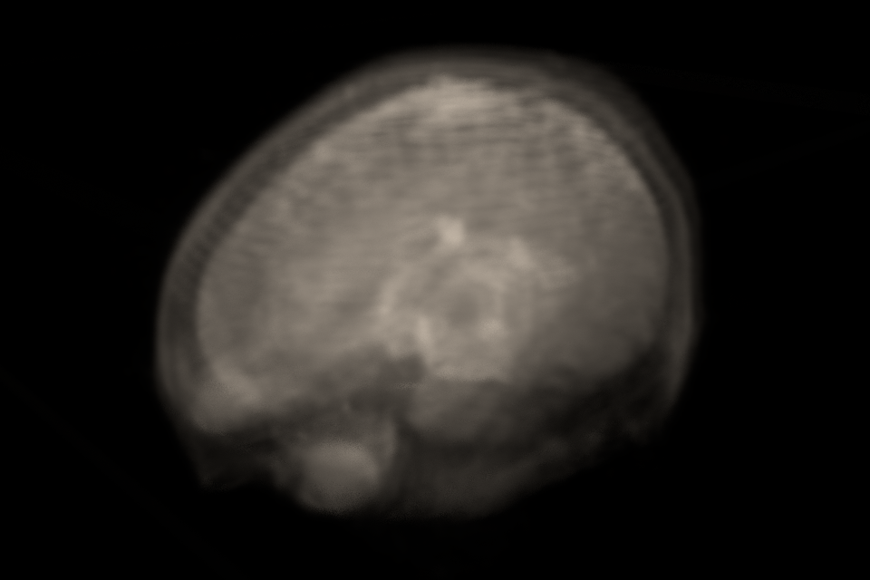
Here is the result:

enter image description here

And the nodes:

enter image description here

It works by chopping up the image and using pixelated z-coordinates to offset the x-coordinates in a stepped manner. The green value node is where you set the number of subimages in the whole image.

Here's the .blend so you can play around with it without having to manually recreate my node tangle. (The voxel scan is a modified version of a CC-0 one I found online somewhere.)

*I downloaded and used it and didn't get any viruses, but don't sue me if it destroys your computer. :)

$\endgroup$
11
  • $\begingroup$ Really interesting, but how can I convert my image sequence into 1 single image? $\endgroup$
    – Bithur
    Commented Sep 2, 2016 at 8:35
  • $\begingroup$ I wonder if you could use a sprite sheet maker? If this addon still works you could configure a texture atlas for the purpose github.com/BinaryPeak/blender-texture-atlas $\endgroup$
    – 3pointedit
    Commented Sep 2, 2016 at 11:21
  • $\begingroup$ @Bithur you could use imagemagick to join the images $\endgroup$
    – sambler
    Commented Sep 2, 2016 at 13:20
  • $\begingroup$ @Bithur You could use something like spritesheetmaker.org. It looks like it generates vertical strips instead of horizontal, so just add the output of the divide node to the Y-coordinate instead of X as it is now. $\endgroup$
    – PGmath
    Commented Sep 2, 2016 at 13:20
  • $\begingroup$ @Bithur OK, I tried and it seems that spritesheetmaker can't handle that many images. I'm looking for one that does. I'll put in in the answer when I do. $\endgroup$
    – PGmath
    Commented Sep 2, 2016 at 13:30
16
$\begingroup$

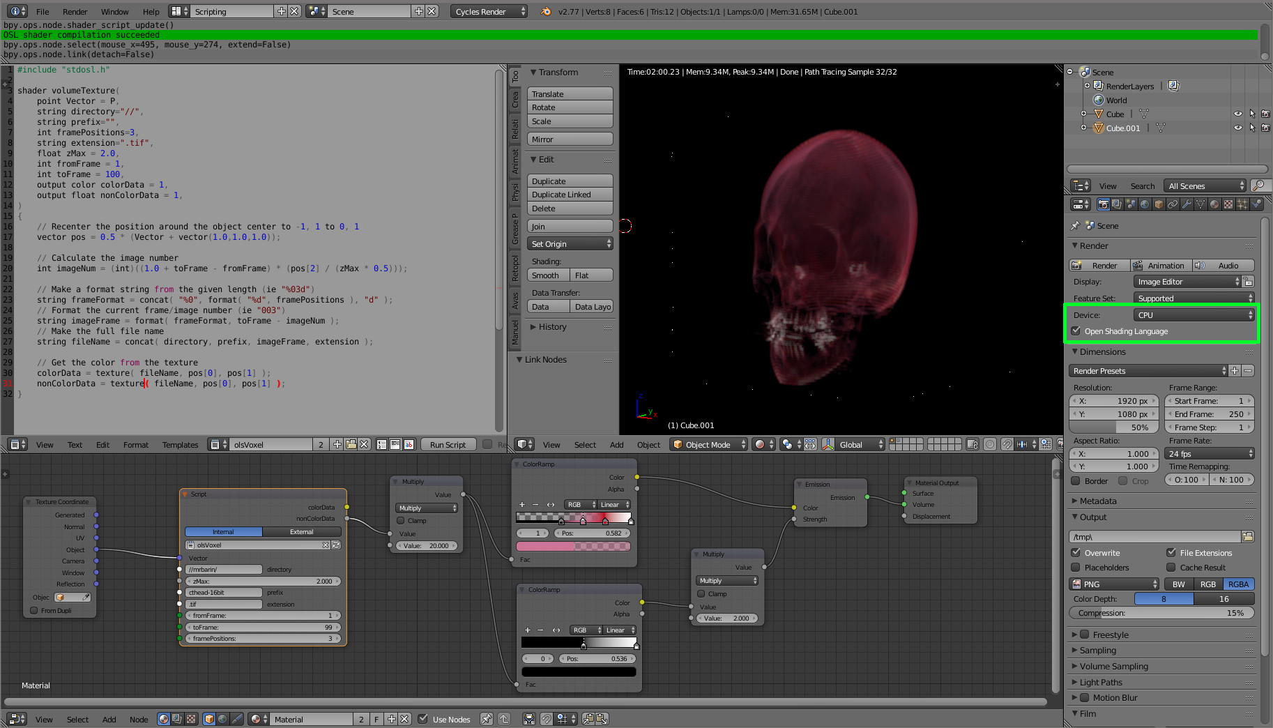
You can use an osl shader to do that.

enter image description here

The code in the capture above creates an osl node. Here are its inputs and outputs :

The input slots

  • Vector : the mapping position (in this config, this must be from object texture coordinates)
  • Directory : the folder where the image files can be found
  • Prefix : the image prefix (image are supposed to be in the format "prefix+counter+extension)
  • Extension : file extension including the dot
  • framePositions : the amount of position to form the file (ie to have 3 position like in "004", set it to 3)
  • zMax : the object elevation (I don't know if there is a way to find the object dimension and center in osl..). So for a default cube, set it to 2.
  • fromFrame : the first image number
  • toFrame : the last image number

The output slots

  • colorData : image data as a color output
  • nonColorData : image data as a non color output (here the image is encoded as non color in the tif files)

The code (see comments)

The principle is to use the Z (or here pos2) value to find the good image making the file name with it.

#include "stdosl.h"

shader volumeTexture(
    point Vector = P,
    string directory="//",
    string prefix="",
    int framePositions=3,
    string extension=".tif",
    float zMax = 2.0,
    int fromFrame = 1,
    int toFrame = 100,
    output color colorData = 1,
    output float nonColorData = 1,
)
{
    // Recenter the position around the object center to -1, 1 to 0, 1
    vector pos = 0.5 * (Vector + vector(1.0,1.0,1.0));

    // Calculate the image number
    int imageNum = (int)((1.0 + toFrame - fromFrame) * (pos[2] / (zMax * 0.5)));

    // Make a format string from the given length (ie "%03d")
    string frameFormat = concat( "%0", format( "%d", framePositions ), "d" );
    // Format the current frame/image number (ie "003")
    string imageFrame = format( frameFormat, toFrame - imageNum );
    // Make the full file name
    string fileName = concat( directory, prefix, imageFrame, extension );

    // Get the color from the texture
    colorData = texture( fileName, pos[0], pos[1] );
    nonColorData = texture( fileName, pos[0], pos[1] );
}

Here is the blend :

Don't forget to set your rendering to CPU and to check 'open shading language'.

$\endgroup$
13
  • $\begingroup$ I can't load the images. Tried to change the directory, tried to create a directory in the .blend path... or there's something else : the volume is white. And what do you mean "color output to float", is it about color management ? (I can only find non-color, raw, linear, sRGB,... no float). Your screenshot looks good, let me try! $\endgroup$
    – Bithur
    Commented Sep 1, 2016 at 18:28
  • $\begingroup$ @Bithur, the filename is hardly coded in the shader (to enhance) but the directory is in the node. Color output to float : the last argument of the shader (dont change it). $\endgroup$
    – lemon
    Commented Sep 1, 2016 at 18:31
  • $\begingroup$ Have you checked 'open shading language' in the rendering panel ? $\endgroup$
    – lemon
    Commented Sep 1, 2016 at 18:32
  • $\begingroup$ I have few minutes but if you want we can talk in chat render farm $\endgroup$
    – lemon
    Commented Sep 1, 2016 at 18:32
  • 1
    $\begingroup$ This works pretty well, although the renders seem fairly slow for my dataset. One issue: this algorithm doesn't interpolate between the datapoints in the z direction (the direction that runs perpendicular to the plane of each image). I changed a few lines of code to allow the osl shader to interpolate between the datapoints: gist.github.com/DanHickstein/0fd6c4a424e193d39bd296ef985bda88 $\endgroup$ Commented Sep 17, 2018 at 17:12
1
$\begingroup$

UDIM

Since UDIM implementation, you don't have to stitch image sequence into Sprite Sheet, to be limited by CPU calculation with OSL or wait for Voxel Data texture implementation (that was a feature lost in 2.8).

You can use image sequence natively now.
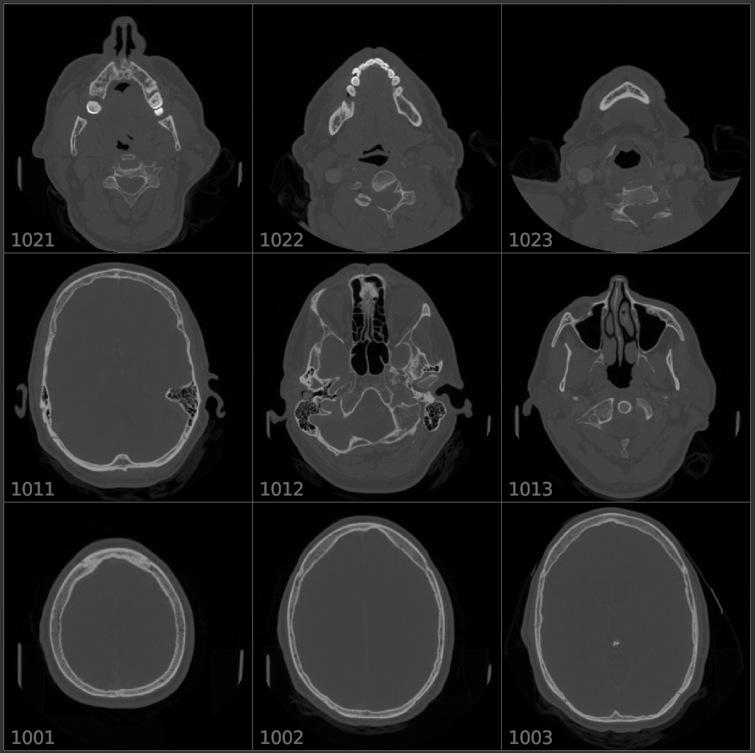
The only thing you have to do is to keep naming convention of your files (.jpg, .png) for UDIM's kind of files ... numbering has to start with 1001, like ... filename_1001.png

Open a new texture in Image Texture node. By selecting the first image, Blender recognize its UDIM format and automatically sets what needed ... grid 10 x ?rows ...

enter image description here

For a Cube object add a material with this node group (UDIM to Volume), it offset images position in texture space.

enter image description here

By default the volume texture is very soft, you need to Multiply color like 100 (it depends on your source data) ...

enter image description here enter image description here

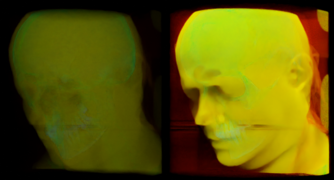
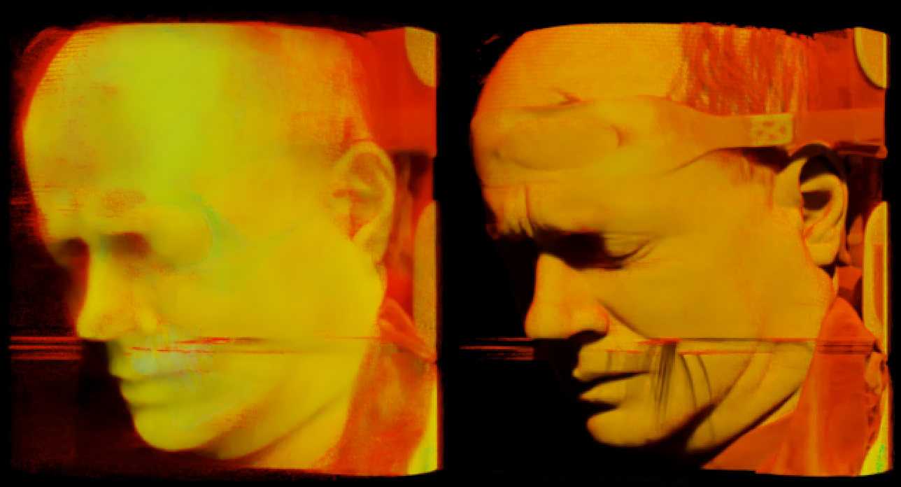
For even more solid effect I used Multiply 1000 (left image) and under Render Properties > Volumes > Step Rate Render/Viewport lowered step at 0.1 ... even hairs are visible now :)

enter image description here

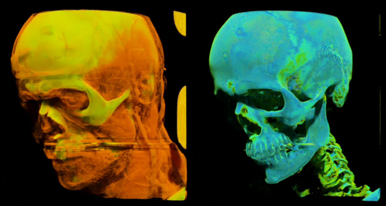
You can place between Image Texture node and Multiply (Math) node black&white Color Ramp node or Map Range node or more complicated math to separate a specific of grey to bring visibility of specific parts, like muscles veins, bones ...

enter image description here

Blend file includes also node group controlling appearance (that I'm not proud of, but works kinda) and Cut Plane node group that is controlled by Plane object. CT Scan data are from https://graphics.stanford.edu/data/voldata/ and node group "UDIM to Volume" by koko_ze.

$\endgroup$

You must log in to answer this question.

Not the answer you're looking for? Browse other questions tagged .