2
$\begingroup$

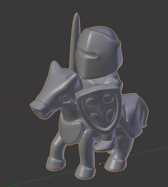
I have 3D printed this knight

enter image description here

(https://i.sstatic.net/CKBjV.jpg) (source: thingiverse), and I wish to make a box for it. I would like to mold the bottom surfaces of the knight so that it would fit neatly into place, while leaving blank space above so that the figure can be inserted down into the box.

I'm new to Blender (and modeling in general), so my first thought was to slightly enlarge the knight mesh and then apply the Boolean difference modifier on a cube. However this would not allow for the knight to be dropped into place.

How would I make this?

$\endgroup$
1

2 Answers 2

4
$\begingroup$

Well there may be a simpler way than what I'm about to propose. However, while I thought maybe the Shrinkwrap modifier might help, it has some issues. It might be helpful if you could post your blend file.

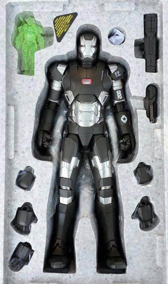
I assume you're trying to make some sort of insert that sort of "nests" around the object, like the foam tray in this picture:
enter image description here

My suggestion: In edit mode select one of the downward-facing faces of your knight, like the bottom of a hoof, or whatever surface faces "down" (or "back") in the package. Now choose Select-->Select Similar-->Normal, and in the bottom part of the tool shelf play with the "threshold" value until you are getting the bottom-and-side surfaces of the mesh. You may also get some unwanted faces in the upper part of the mesh, that's okay for now. Once you have the desired regions selected, duplicate them (Shift-D) then split them into a new object (P).

Go into object mode, select the new object you created, then go into edit mode. with any luck you'll be able to easily select and delete the "wrong" faces. Select linked (L) may allow you to select entire "islands" of wrong faces based on selecting one unwanted face.

Once you have only the correct faces left: select all (type A), Extrude (E), type Z to constrain to the Z axis, and pull upwards to create "sides" for your hull/nest. Without changing the selection, type S, Z, 0 (zero), Enter. That will make the selected vertices coplanar (and, more importantly, make the sides come to a constant height). Finally, type X and choose "dissolve faces". You can delete the ngon that results. You should have a shell that will fit the bottom part of your knight. You can scale it up slightly to allow for a fit, although I think the right way to do this is with Shrink-Fatten (edit mode, select all, Alt-S).

Modeling the rest of the insert (the flat faces) could be approached in various ways. You might want to add a plane (in edit mode), center it over your hull surrounding the top edges, delete the plane's face (only, leaving the vertices and edges), select the edge loop around the top of the "nest" and the edge loop of the plane, and choose "Mesh-->Faces-->Fill" to create non-ngon faces.

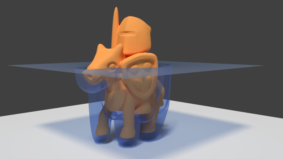
EDIT: lol your knight figure is way more complicated to work with - I remeshed it to get somthing simpler to manipulate. After creating the hull as described above, it was still too funky to work directly, so I ended up creating a subdivided plane and using a shrinkwrap modifier (Mode: Project, Axis: Z, Direction: Negative) that wrapped over the hull object. And then a bunch of tweaking, shrink/fattening, subsurfaces, etc. Wish it was a simple process to describe.
enter image description here

$\endgroup$
0
4
$\begingroup$

Okay, there's another technique that I think might be preferable. But again you'll need to tweak it to get it the way you want.

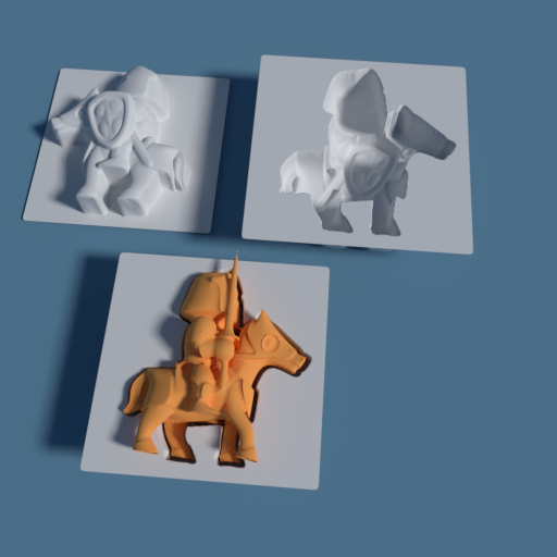
enter image description here

This one involves baking a heightmap of the figurine and using it to displace a plane using the "displace" modifier. Pick whichever side of the figurine you want for the heightmap.

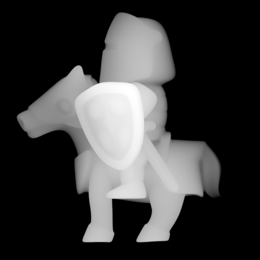
enter image description here

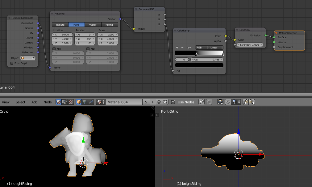
Here's how I baked the heightmap. I created a copy of the figurine, set it to smooth shading, and gave it an emission shader with a color generated from the B vector (the Z-axis vector) of the object's Generated texture coordinates.

enter image description here

I added a black plane, also using an emission shader, to help define the zero level.

To render this correctly, you need to set up your camera as orthographic camera, with a square aspect ratio, positioned at the right place and height to capture the map. You don't want any lights in the scene, nor any objects that might cast shadows (turn off Use Environment in the Render Layers tab, and Shadows (in the Light Paths section of the Render tab) while you're at it). The emission shaders shouldn't show any shadows I think, but why take chances?

With your heightmap rendered and saved, you can then use it as the texture for a "Displace" modifier on a subdivided plane. A displace value of .5 was right for me.

From there, you'll need to tweak things with subsurfaces, maybe some shrink/fatten scaling to ensure there's space for the object, etc.

$\endgroup$
2
  • $\begingroup$ There is a Separate XYZ node that you can use instead of Separate RBG $\endgroup$ Commented Jan 18, 2018 at 2:30
  • $\begingroup$ Thanks, yes. Honestly I just used the separate rgb out of habit. But absolutely, separate XYZ would do the same thing, and it's more intuitive. $\endgroup$
    – risingfall
    Commented Jan 18, 2018 at 2:45

You must log in to answer this question.

Not the answer you're looking for? Browse other questions tagged .