26
$\begingroup$

Actually, it's not so simple as the title suggests... :)

I might be asked to animate something like this - https://youtu.be/1A3vaJaNDLY?t=132

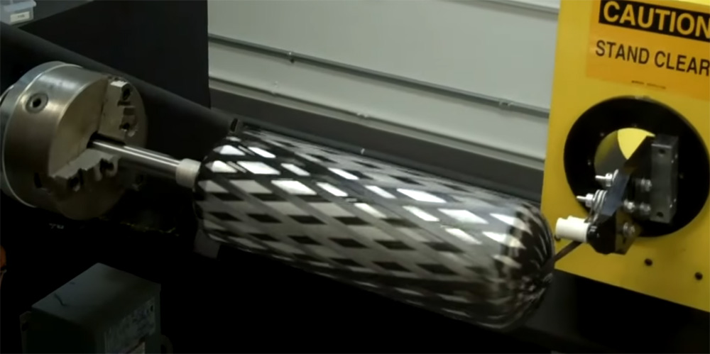
Here's a still from that video:

enter image description here

It's the process of doing helical wrapping of carbon fiber a ribbon around a pressure vessel. And later in the video you'll see a simpler activity of hoop wrapping, which I'd also need to animate.

I've got some basic experience with Blender (e.g. https://vimeo.com/207323639), but I have no idea where to start with this kind of animation! At this point I haven't spoken to my client, so I don't know whether this will be requested; but I'd value input from Blenderheads here so that if I'm asked for it, I'll be able to respond with "sure!", or "can't be done", or "sure, but it'll cost ya!". :)

Pointers, anyone? Thanks!

$\endgroup$
2
  • $\begingroup$ Without showing anything for you, my gut feel says that Brush and Canvas would be a good approach here. I personally would study up on this, and see if this resonates with you at all. $\endgroup$
    – Rick Riggs
    Commented Mar 30, 2017 at 14:55
  • $\begingroup$ Hm. That might go part way, maybe with some clever Python to define the paint path. However, I would also need to animate the ribbon as it comes from the pulley, through the air, onto the vessel. In other words, just animated painting doesn't convey the wrapping process adequately. So there has to be some dynamic geometry, I would think. $\endgroup$ Commented Mar 30, 2017 at 15:24

4 Answers 4

37
$\begingroup$

enter image description here

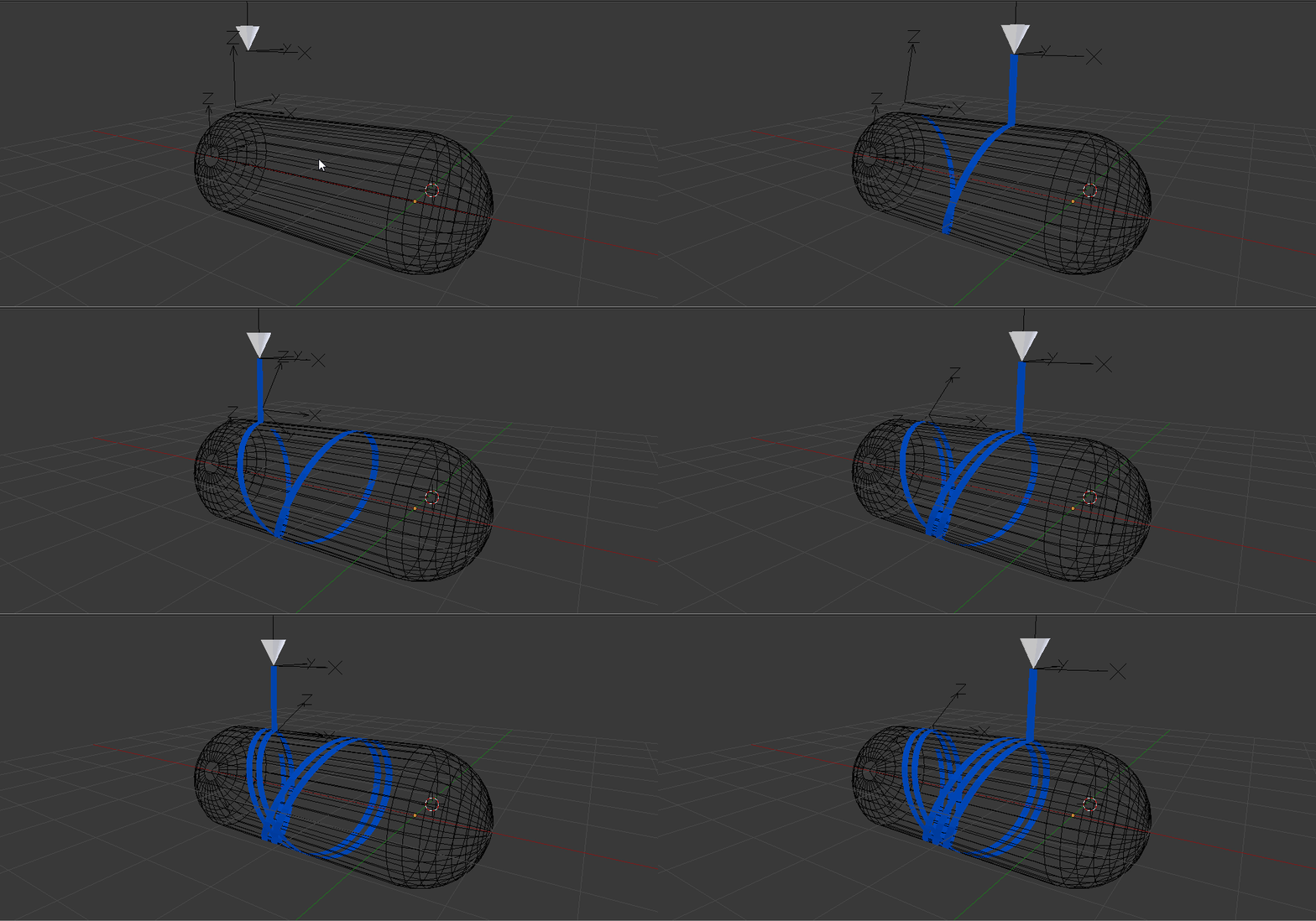
The strip follows the cone using this principle:

  • The cylinder turns due its parent, an empty which rotates
  • The strip object turns too, with the same empty as parent
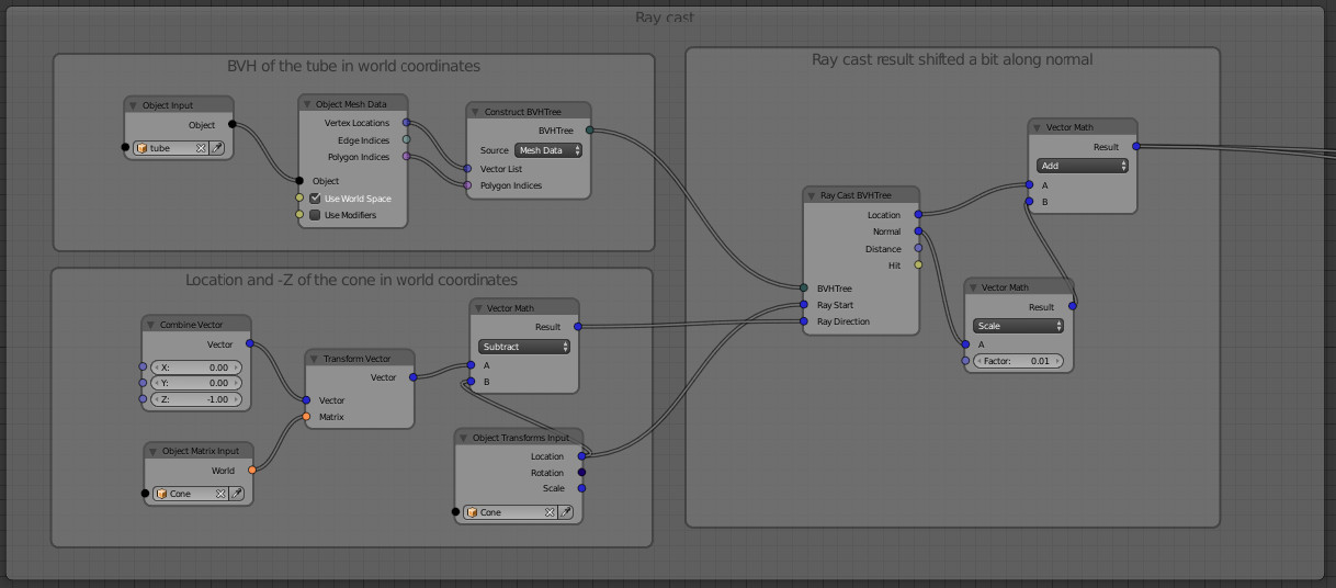
  • The cone orientation (-Z axis) and location are used to ray cast on the cylinder: this gives a new position on the cylinder to complete the strip

All that is done using Animation Nodes.

More detailed steps:

  • Calculate the cone location and -Z orientation in world coordinates
  • Raycast on the cylinder from these previous parameters
  • This raycast gives a position on the cylinder and the normal of the hit face
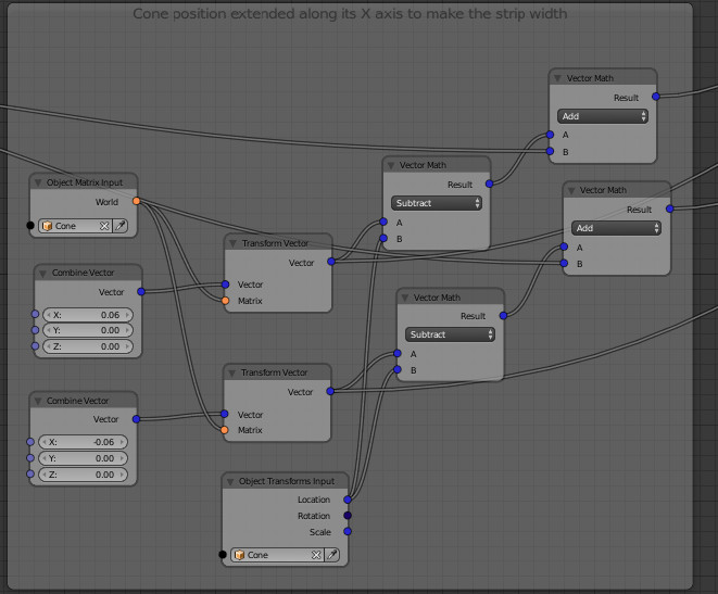
  • Calculate the new strip part position from this previous data, extending it along the cone X axis and shifting it a bit along the face normal
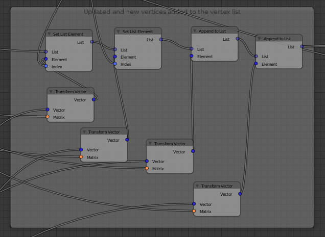
  • This calculation replaces the last two strip vertices
  • Add new two vertices to the strip and place them at the cone position
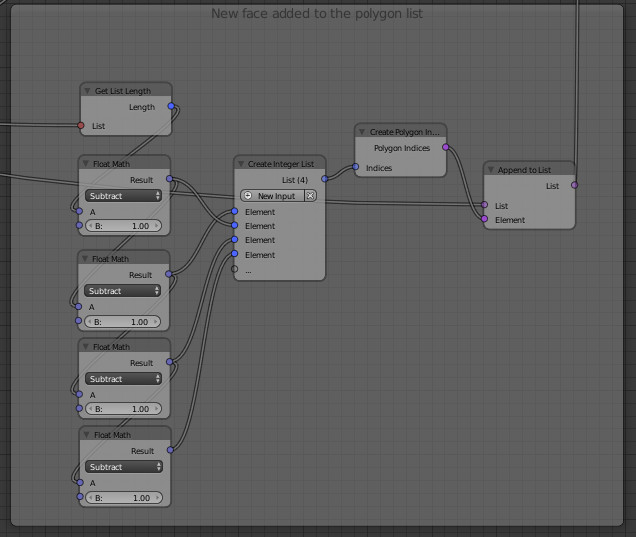
  • Make a new face for these last 4 vertices
  • Input back all these vertices and polygons in the strip geometry

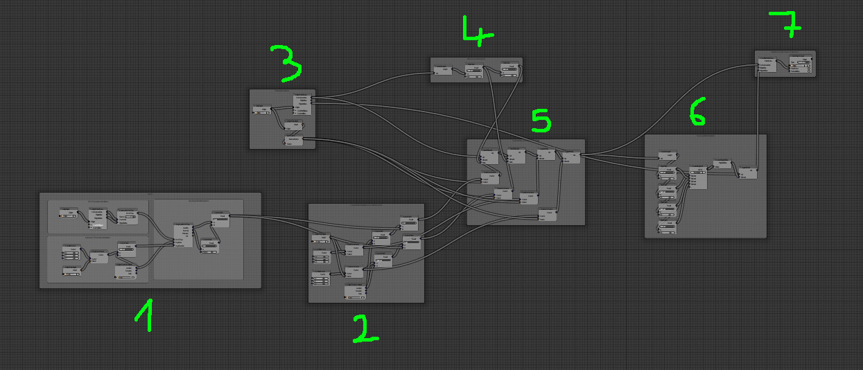
The overall cartography:

enter image description here

1/ Calculate the ray cast and new strip part's position

enter image description here

2/ Give a width to the strip

enter image description here

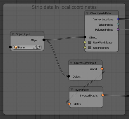
3/ Extract strip's current geometry

enter image description here

4/ Calculate last 2 previous vertices index

enter image description here

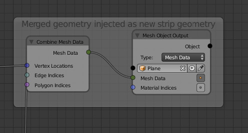
5/ Injects updated and new vertices in the strip data

enter image description here

6/ Make a new face from the last 4 vertices

enter image description here

7/ Put all back to the strip data

enter image description here

Note:

  • To make it work, the strip have to include at least an edge at the beginning of the animation.

  • This node setup is "constructive", at each frame it creates new vertices, and this is not rolled back at the end of the animation. So, to replay it, edit the strip and delete all its vertices except the two first ones.

To do list:

  • Constraint the cone -Z axis to always point to the cylinder, as if not the raycast will fail

  • Raycast on the strip itself too so that it superimposes on both the cylinder and on itself

  • Not only raycast one (middle) point, but the two extremities of the newly created strip's vertices

enter image description here

Another example, following the comment:

enter image description here

$\endgroup$
7
  • 1
    $\begingroup$ Thanks, Lemon - that's intense! I think if I study what you've done I'll double my Blender knowledge. :) One thing, though... The ribbon arrives at the tangent of the vessel, not at the normal. The video in my original post shows this. $\endgroup$ Commented Mar 31, 2017 at 14:26
  • $\begingroup$ @DanBennett, yes, I had no time to go further, but, the main point here is to do so the cone always points -Z to the tube (as the ray cast is along this axis). If you do that (by a constraint or other), it will continue to "project" the strip all around the tube. Now, also read the "to do list" at the end of the answer. $\endgroup$
    – lemon
    Commented Mar 31, 2017 at 14:50
  • $\begingroup$ @DanBennett, I've quickly added another example, so that you can see what I mean $\endgroup$
    – lemon
    Commented Mar 31, 2017 at 14:57
  • $\begingroup$ Thanks, Lemon - your answer's very good. The method of adding vertices to the strip is very powerful - I wasn't aware it was possible. I don't think your to-do list indicates that the main change that's needed is for the ribbon to arrive at the vessel on a tangent, not on its normal. At the moment it looks like the incident ray is a paint brush, rather than a ribbon that's under tension. $\endgroup$ Commented Mar 31, 2017 at 15:10
  • $\begingroup$ @DanBennett... oh, ok.. I see what you mean now. The orientation of the cone in this configuration needs the cone to point to the tube. But this ray cast could be done from every directions. The only needed point is the ray has to hit the tube. See what I mean? Of course, this is not a real physical constraint here. What I have in mind is placing and animating thing in the good orientation may do the job. In certain meaner, the same way the real machine is coded to orientate things correctly $\endgroup$
    – lemon
    Commented Mar 31, 2017 at 15:15
17
$\begingroup$

This sounds quite complex to do properly.
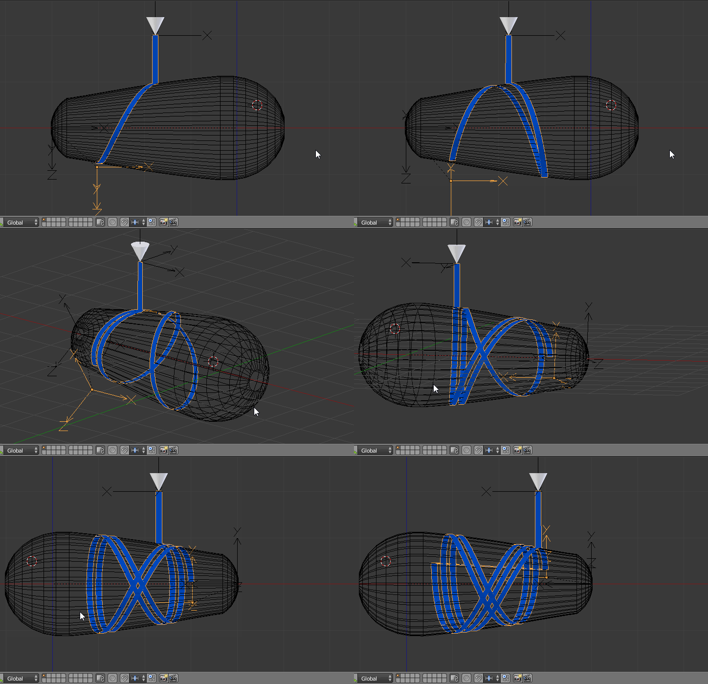
enter image description here

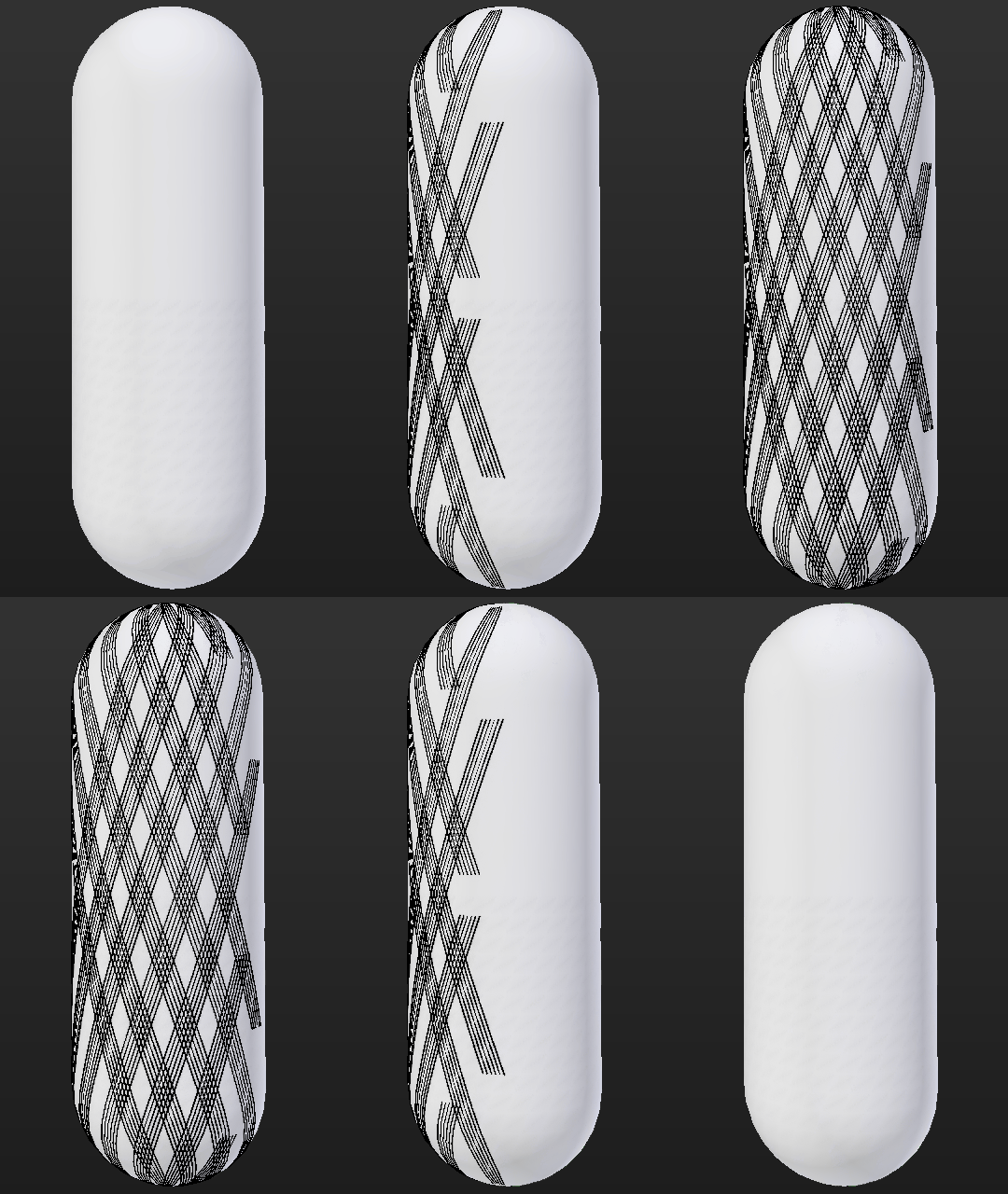
One simply way to fake it might be using curves and animating the Bevel Factor property, though it will probably still require quite some manual tweaking.

Get your base cylinder shape going, on a copy of it apply a Simple Deform modifier to get the twisted shape (save the original object intact).
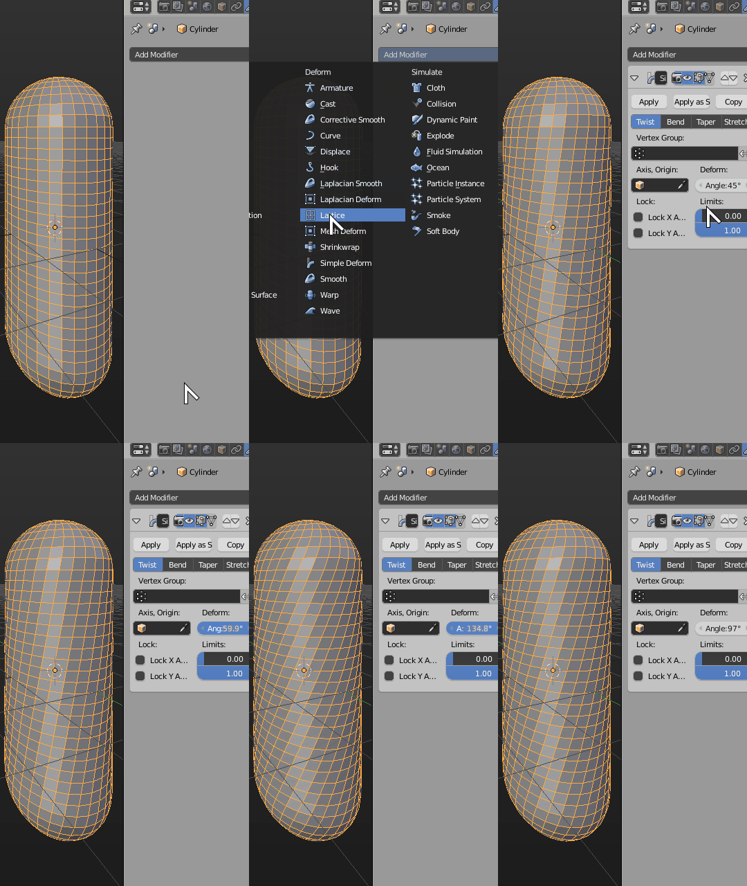
enter image description here

Apply all modifiers and using a loopcut you can extract a rough shape of the wires wound around the capsule shape.

Duplicate the edges, separate them into a new object, converte it to a curve them give it a bevel width.
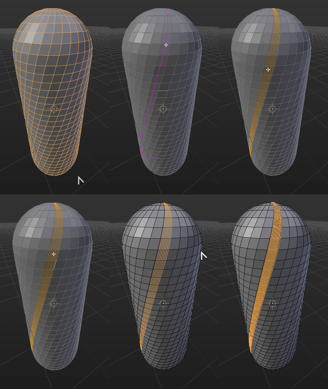
enter image description here

You can now animate the Bevel Start or Bevel End factor to obtain a wound effect. If any stray segments end up animating in the opposite direction just invert their direction in edit mode.
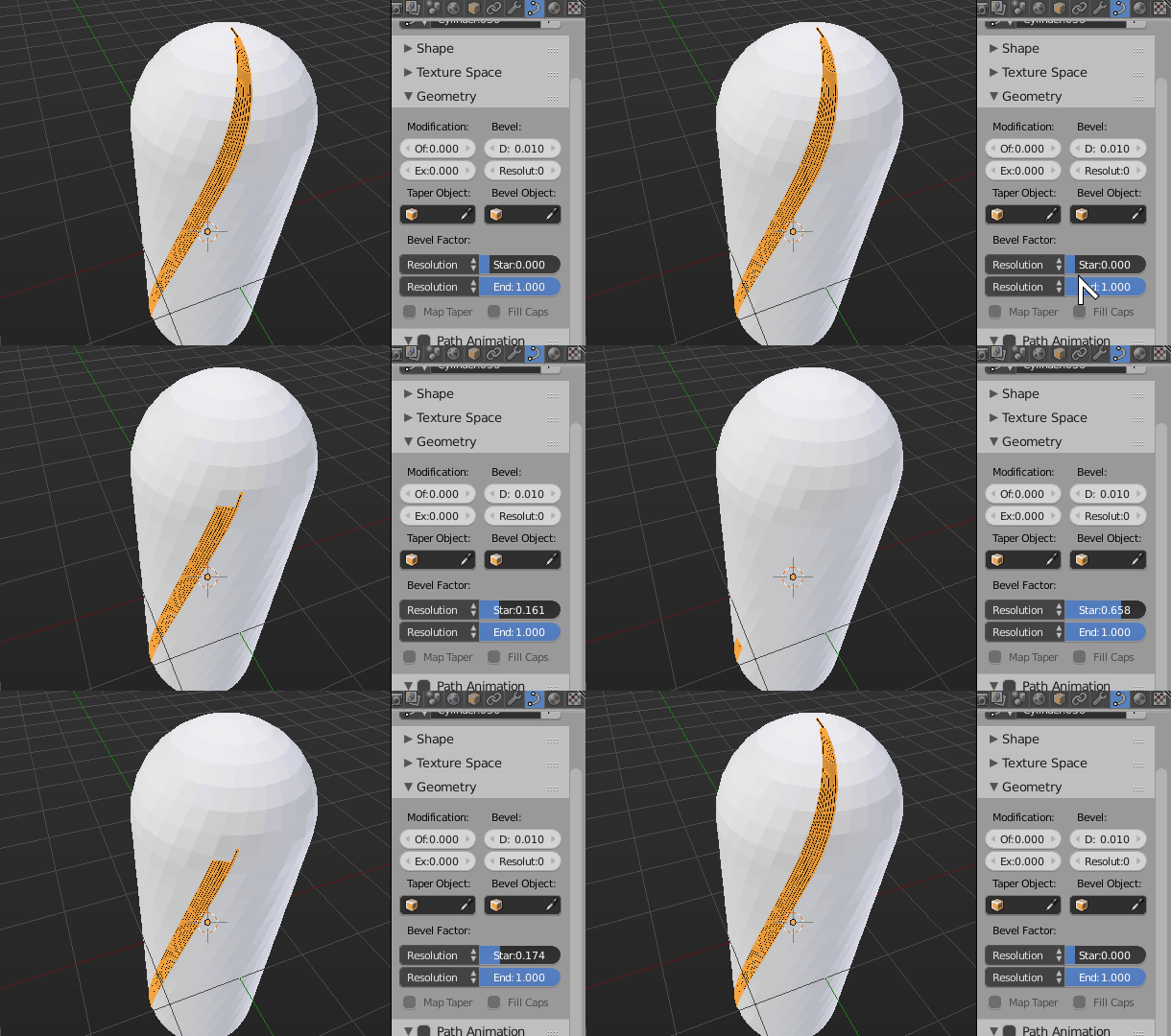
enter image description here

By duplicating you curve object multiple times around the capsule and offsetting the animation keyframes you may obtain an approximation of the desired result.

enter image description here

You could also try and combine all curves into one, and use a second bevel object curve to simulate the umtiple wires instead (may be more efficient). You might additionally try to combine all curves into one, merging the ends in edit mode so they become a "single continuous spool" and you don't have to deal with animation offsets and multiple objects.
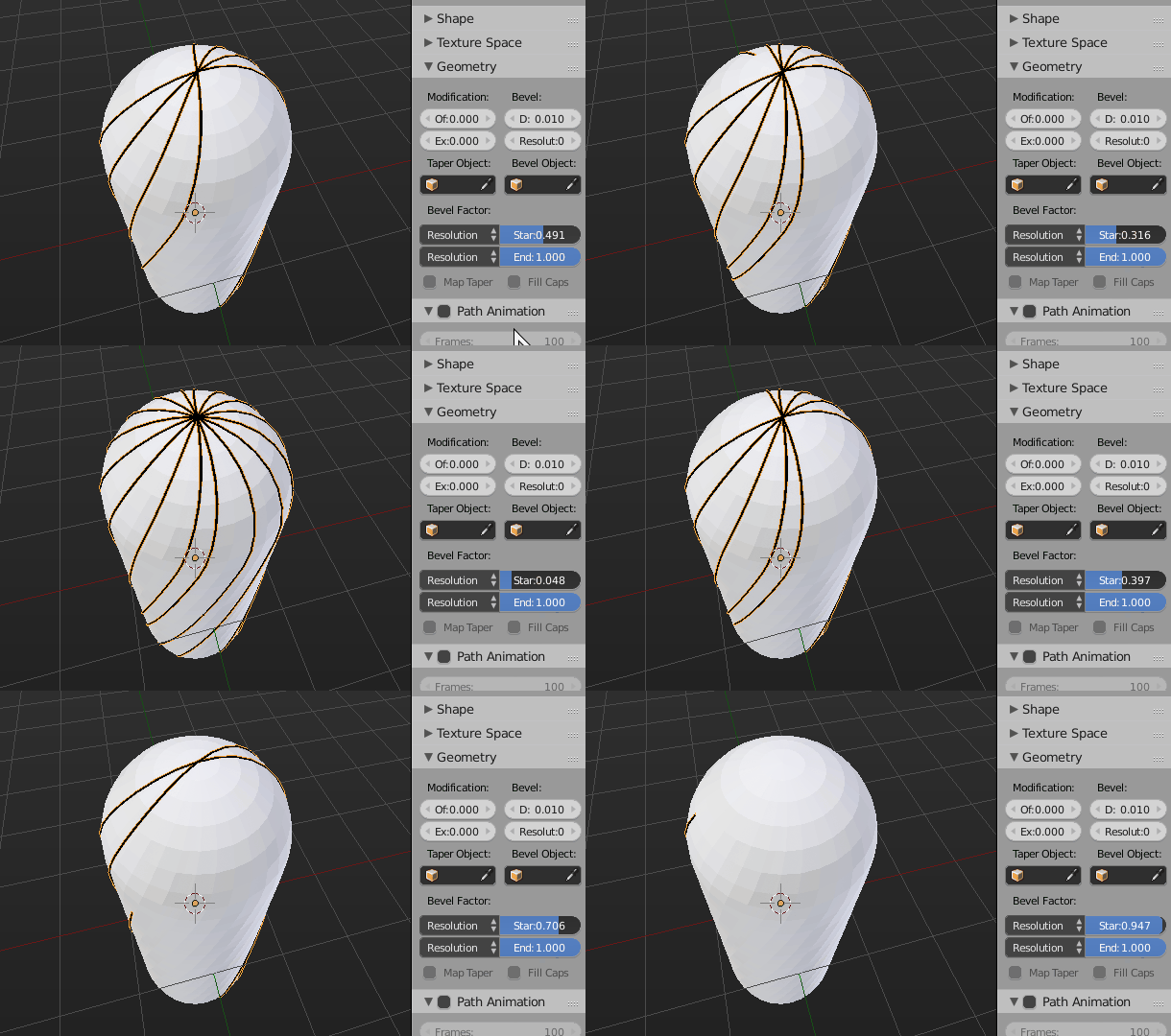
enter image description here

Offsetting the keyframes properly may be the key the hardest part, the ARewo addon may help there, although from my superficial testing I could not get it to work with these curve objects.

Edit

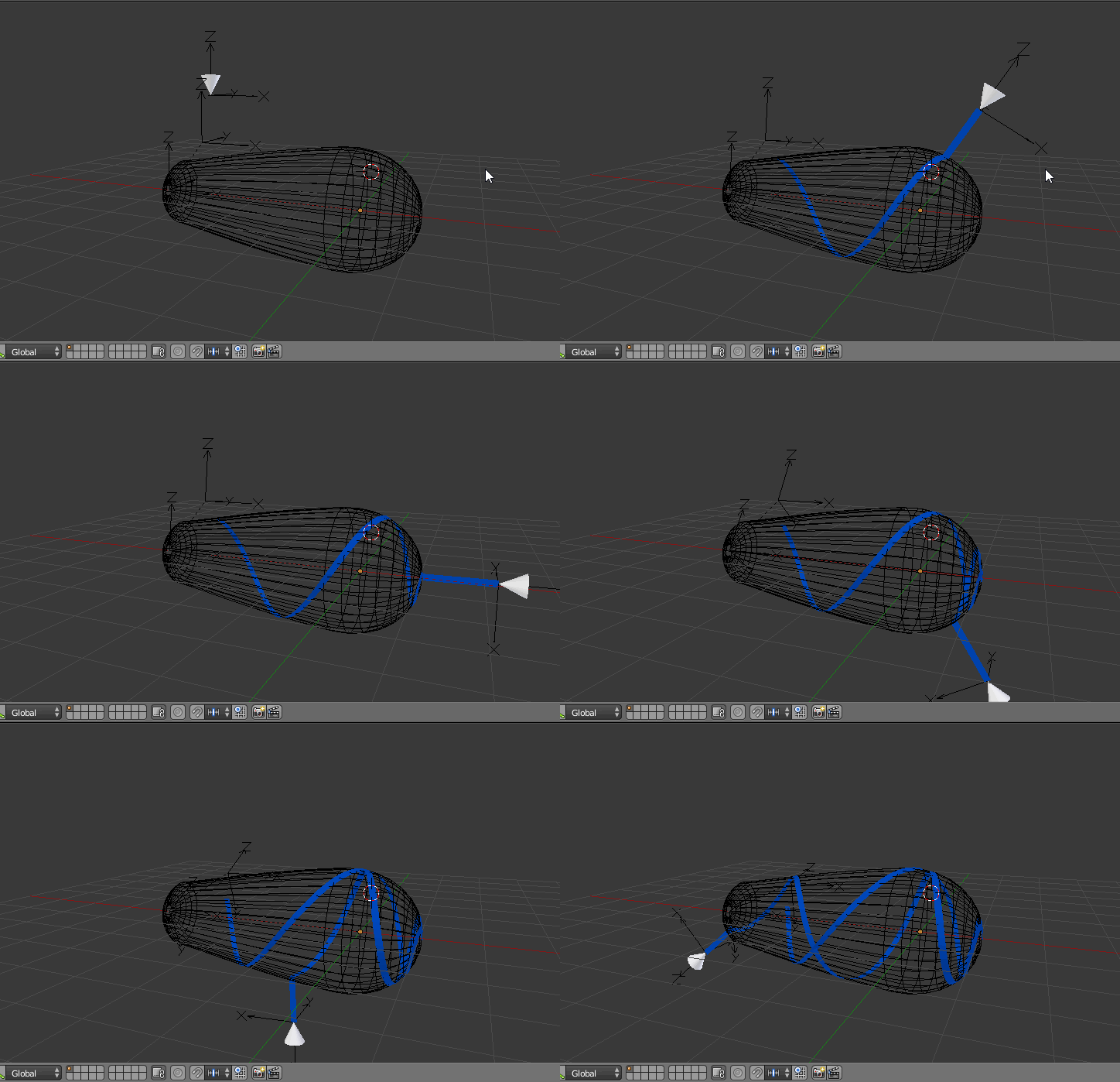
As for the wire coming from the applicatior tool, you could possibly achieve this by using a second fixed bezier curve object that would extend from this animated applicator, going back and forth, and having its other end hooked to an empty object.

You could then add a Follow Path constraint to this Empty object, attached to the winding curve. If set up correctly the Follow Path constraint should be easy to synchronized with the curve Bevel Factor animation, since they essentially both use the same curve and have thus the exact same length.
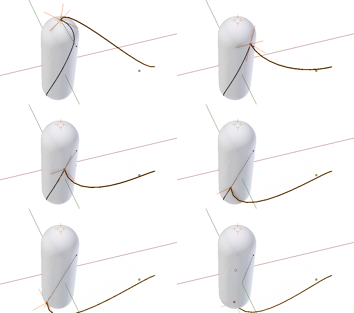
Hook Bevel synchronization

$\endgroup$
4
  • 2
    $\begingroup$ That's amazing - thanks! OK, so I can see how this can be used to apply the helical windings - and it's a great help with getting the look right for the finished vessel. However, I may also need to show the winding process happening, with the ribbon of threads coming from the applicator tool. This would imply that I would somehow need to hook a curve to the leading edge of the bevel factor's effect. I'm guessing that would be hard to do...? $\endgroup$ Commented Mar 30, 2017 at 19:05
  • $\begingroup$ The wire coming from the applicator could probably be easily done with another curve hooked to an empty with a path constraint. Answer updated to reflect that. $\endgroup$ Commented Mar 31, 2017 at 1:00
  • $\begingroup$ Thanks, Duarte. It's not quite right - the ribbon arrives at the tank on the tangent - take a look at the video in my original post. $\endgroup$ Commented Mar 31, 2017 at 14:19
  • $\begingroup$ Just invert the bevel animation direction, or the empty position, should be easy to fix, the underlying principle should be the same. $\endgroup$ Commented Mar 31, 2017 at 16:42
4
$\begingroup$

So here is a process that may not be super ideal, but it would work:

For this setup, I used a cylinder, a spiral around the cylinder, another larger cylinder to do som boolean difference, and a driver on the head.

The obvious limitation to this, is that you would have to make this iterative (eg. run the first pass, copy the scene/file, create the setup again, do your crossover pass, copy the scene/file, create the setup again, do the pass that goes the other direction, repeat, repeat, repeat.

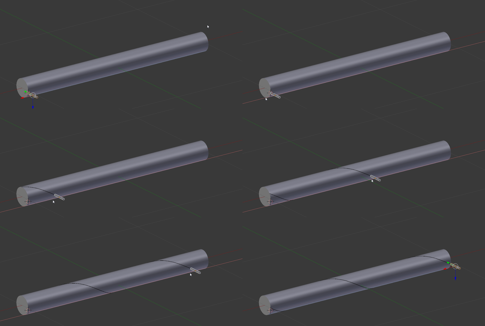
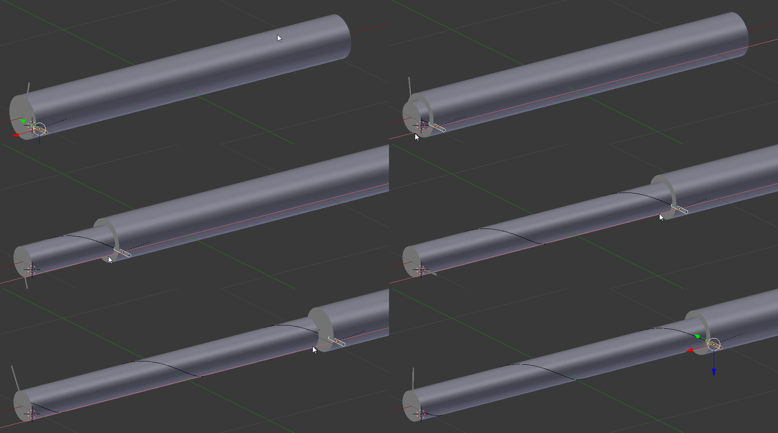
Here's that first scene setup in action:

result

The Larger cylinder that is doing the boolean is parented to the mahine head, and exist in a hidden layer.

The spiral is parented to the smaller cylinder.

The driver itself is on the smaller cylinder that rotates linear to the movement of the head.


To give you a better idea of what is going on, look at the left hand side of the cylinder, I added a flag.

Also note, that I am showing all layers, so you can see the Boolean Difference cylinder.

enter image description here

$\endgroup$
4
  • 1
    $\begingroup$ Thanks, Rick. This looks good, but is it simply sliding a (Boolean-chopped) spiral along the cylinder? Unless I'm visualizing this wrongly, I think this would struggle to look correct if the cylinder were rotating along its long axis, which it would be in my animation, complete with showing already-laid windings on its surface. $\endgroup$ Commented Mar 30, 2017 at 21:01
  • $\begingroup$ This is spinning, it is spinning at a rate of 720° for every 2 units that the head is moving. The driver is taking care of this relationship. $\endgroup$
    – Rick Riggs
    Commented Mar 30, 2017 at 22:37
  • $\begingroup$ I appended my answer so you can see it a little better. $\endgroup$
    – Rick Riggs
    Commented Mar 30, 2017 at 22:43
  • $\begingroup$ Part of you comment is correct. After animating this one sweeping pass from left to right, you would copy the scene, and break/apply the boolean & driver, and set all of this up again to do your crossover scene, copy the scene -> break/apply -> setup for the next direction. wash -> rinse -> repeat, being sure to record your sequence for every scene. Once you have done all of this labor, you could stitch all of your scenes together in the VSE or whatever you choose. $\endgroup$
    – Rick Riggs
    Commented Mar 30, 2017 at 22:50
2
$\begingroup$

Here is a solution for a simpler case like this one:

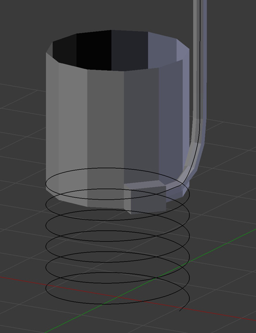
  • Create 3 objects: The cylinder, the rope (a cylinder with an Array modifier and a Curve modifier) and the curve.

enter image description here

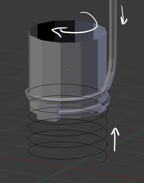
  • Rotate the cylinder with some keyframes (here -400°). Move up the curve, move down the rope (or increase its Array count) so that the rope seems to follow the the cylinder. Make sure that each of your animations interpolation is linear (in the Dope Sheet press T > Linear).

You can find more at Animating wire/cable/rope wrapping around a cylinder

enter image description here

$\endgroup$

You must log in to answer this question.

Not the answer you're looking for? Browse other questions tagged .