(Using Blender 3.6.5)
Objective
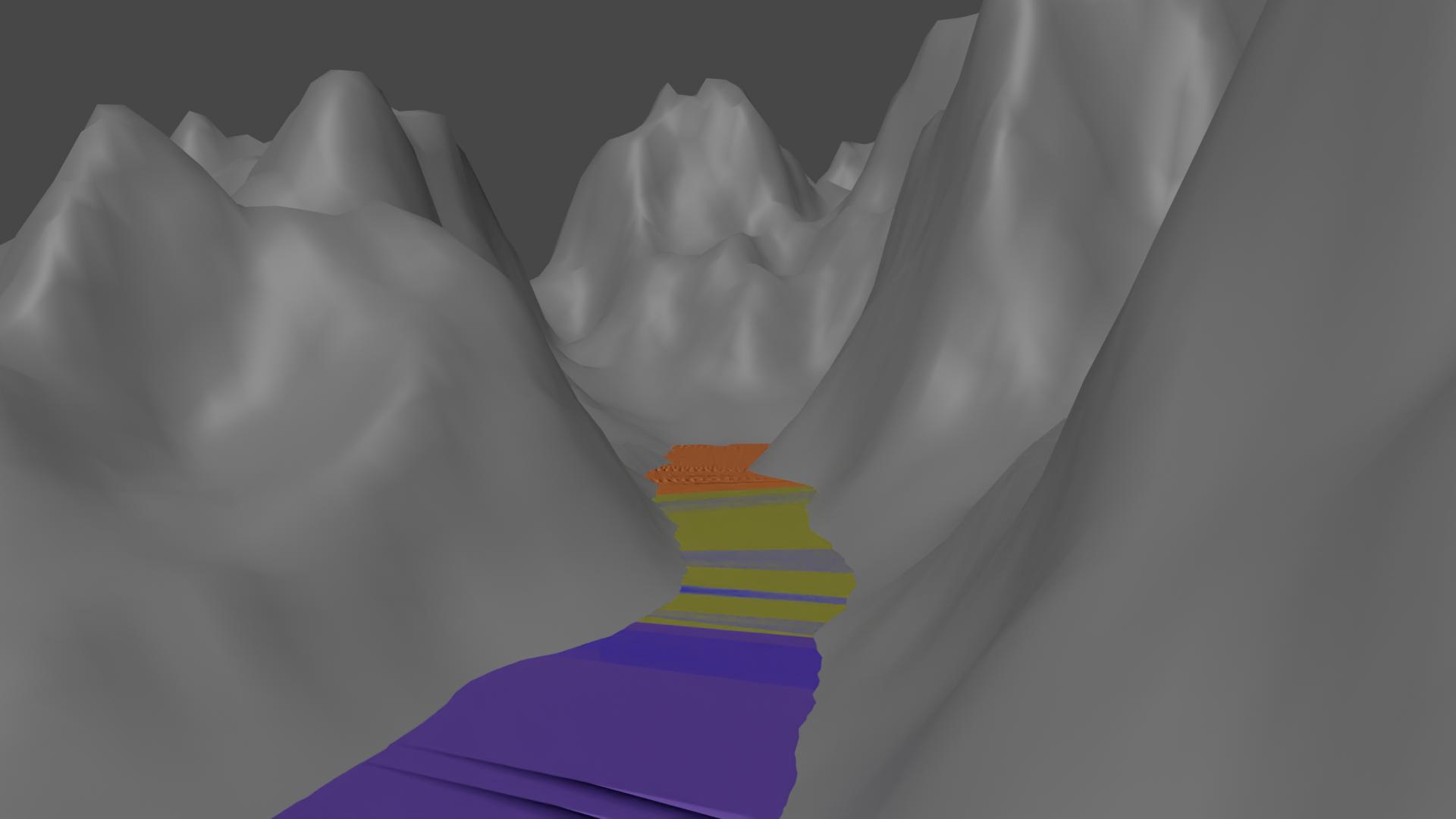
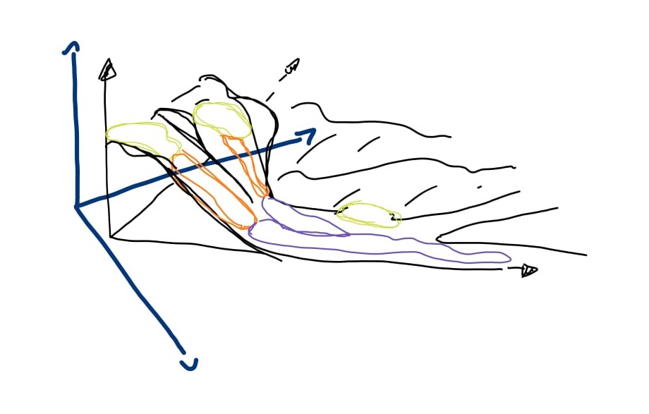
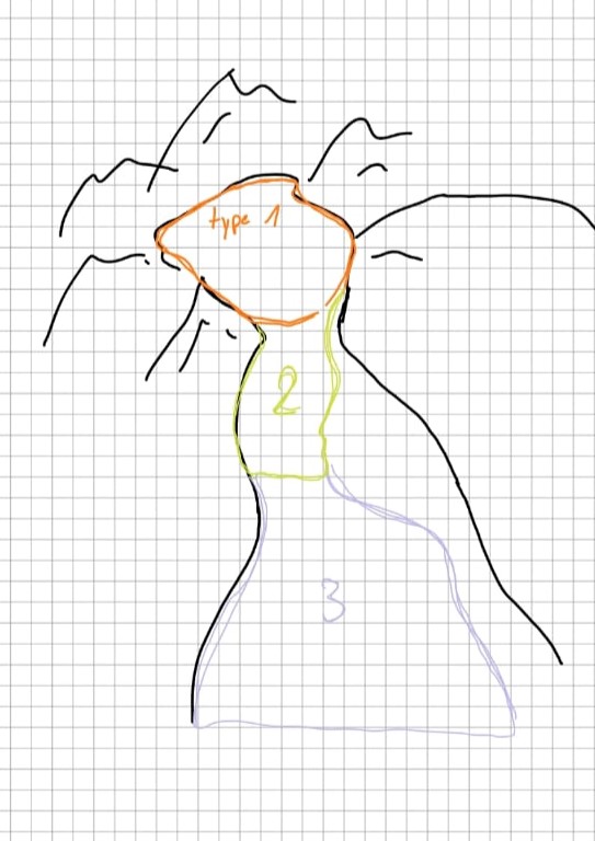
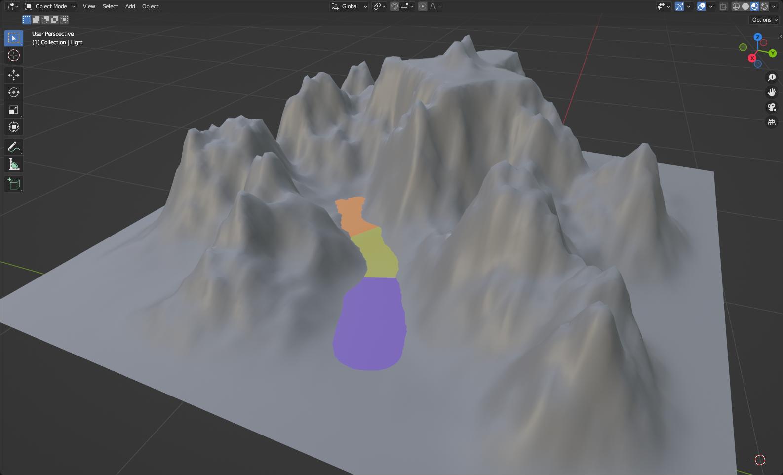
To model the water surface of a stream flowing downhill, coloured by types of flow.
Approach
Extrude a Bezier curve following the bottom of the stream, after a slight vertical shift, to generate a surface larger than the valley.
Procedure
Step 1: Visualise the slope
 1. In the Shader Editor:
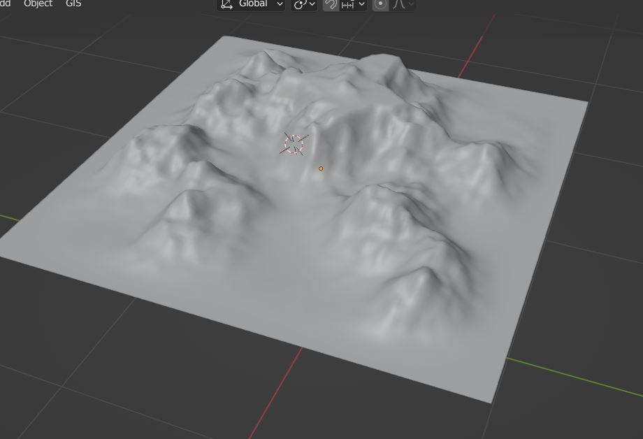
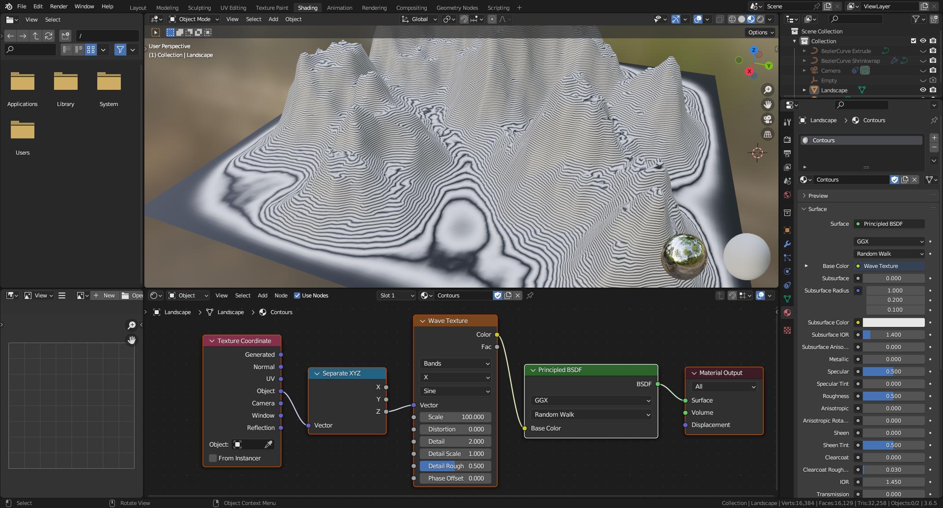
1.1. The vertical coordinate Z of the landscape is recovered by combining Texture Coordinate and Separate XYZ nodes.
1.2. Z is input in a Wave Texture node which Scale parameter is adjusted to sample the valley of interest.
1.3. The result is iso-elevation contour lines.
Step 2: Draw the curve following the valley
 2. In Edit Mode/Top view:
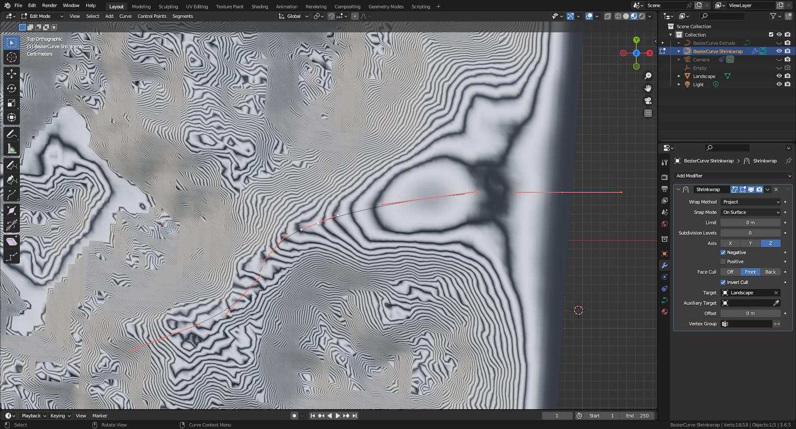
2.1. Add a Curve/Bezier object above the landscape.
2.2. Add more control points above the landscape also. Move these in (X,Y) directions and adjust tangents to follow the valley floor, using the contours as guideline.
2.3. To put these control points on the landscape mesh, add a Shrinkwrap modifier. Set Wrap Method to Project along Negative Z Axis. Select the landscape as Target. Check the Apply on Spline icon to project the control points rather than the curve.
2.4. Duplicate this Bezier curve, to keep a copy before destructive actions, and Apply the modifier to the copy.
Step 3: Extrude the duplicated curve to model water surface
 3. In Edit Mode, using the Curve Context Menu:
3.1. Select Set Handle Type/Aligned if the projection at step 2 misaligned left and right handles, to keep a smooth water surface whatever the underlying landscape slope variations are.
3.2. Set the Tilt of all control points to 90 degrees.
3. In the Object Data Properties panel:
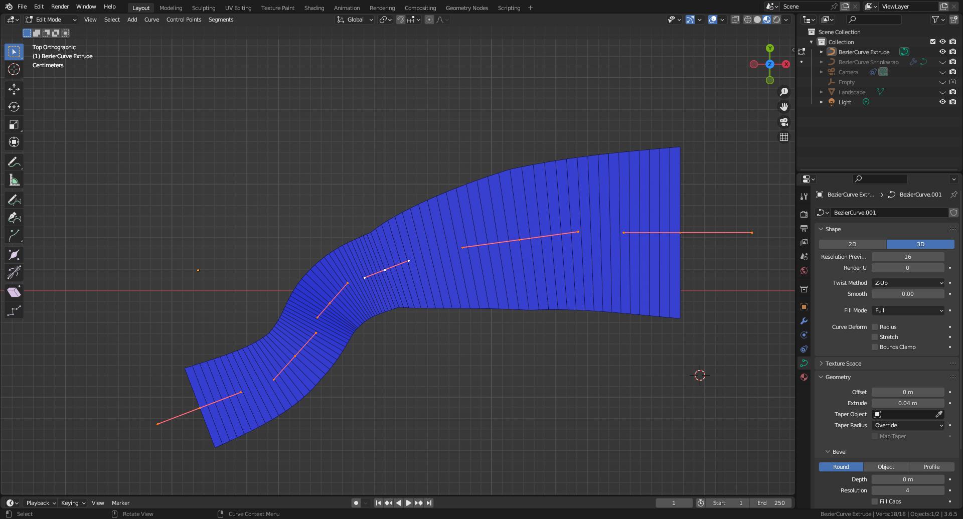
3.3. Set Twist Method to Z-Up to keep extruded segments horizontal.
3.4. Adjust the Geometry/Extrude value, avoiding overlap of extruded faces in regions of small radius of curvature. Otherwise, stairs are generated instead of a smooth surface.
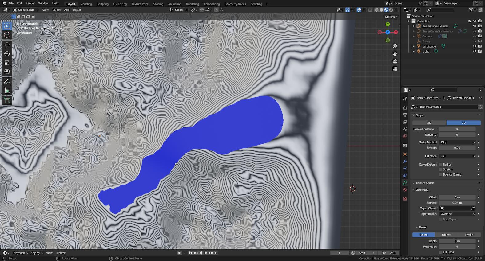 3. In Edit Mode:
3.5. Move each control point in Z direction, or perpendicularly to the landscape mesh, to adjust the width of the apparent water surface.
3.6. Adjust tangents to keep the surface aligned with the underlying landscape slope, or to create horizontal lakes.
3.7. Using the Curve Context Menu, adjust the Radius at control points where the extruded distance is too small/too large according to the local stream width.
Step 4: Specify different materials/colours
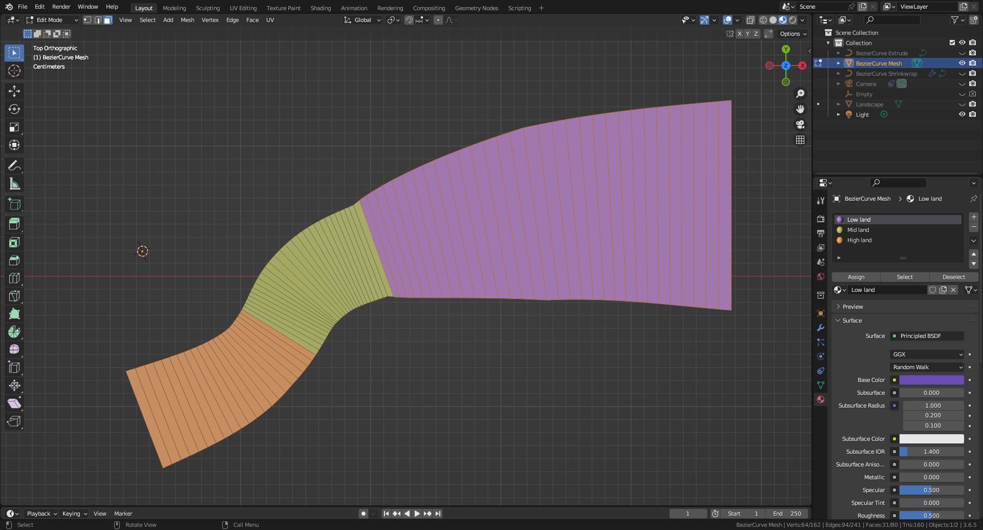 4. In Object Mode:
4.1. Convert the extruded curve from step 3 to Mesh, keeping the original.
4. In Edit Mode, using the Material Properties panel:
4.2. Select faces sharing the same type of flow.
4.3. Select a material and Assign it to the selected faces.
4.4. If a mesh per type of flow is required, from the Face Context Menu choose Separate/By Material.
Resources


