Woven Sleeve with Geometry Nodes
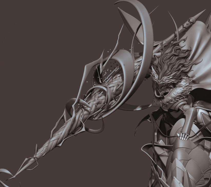
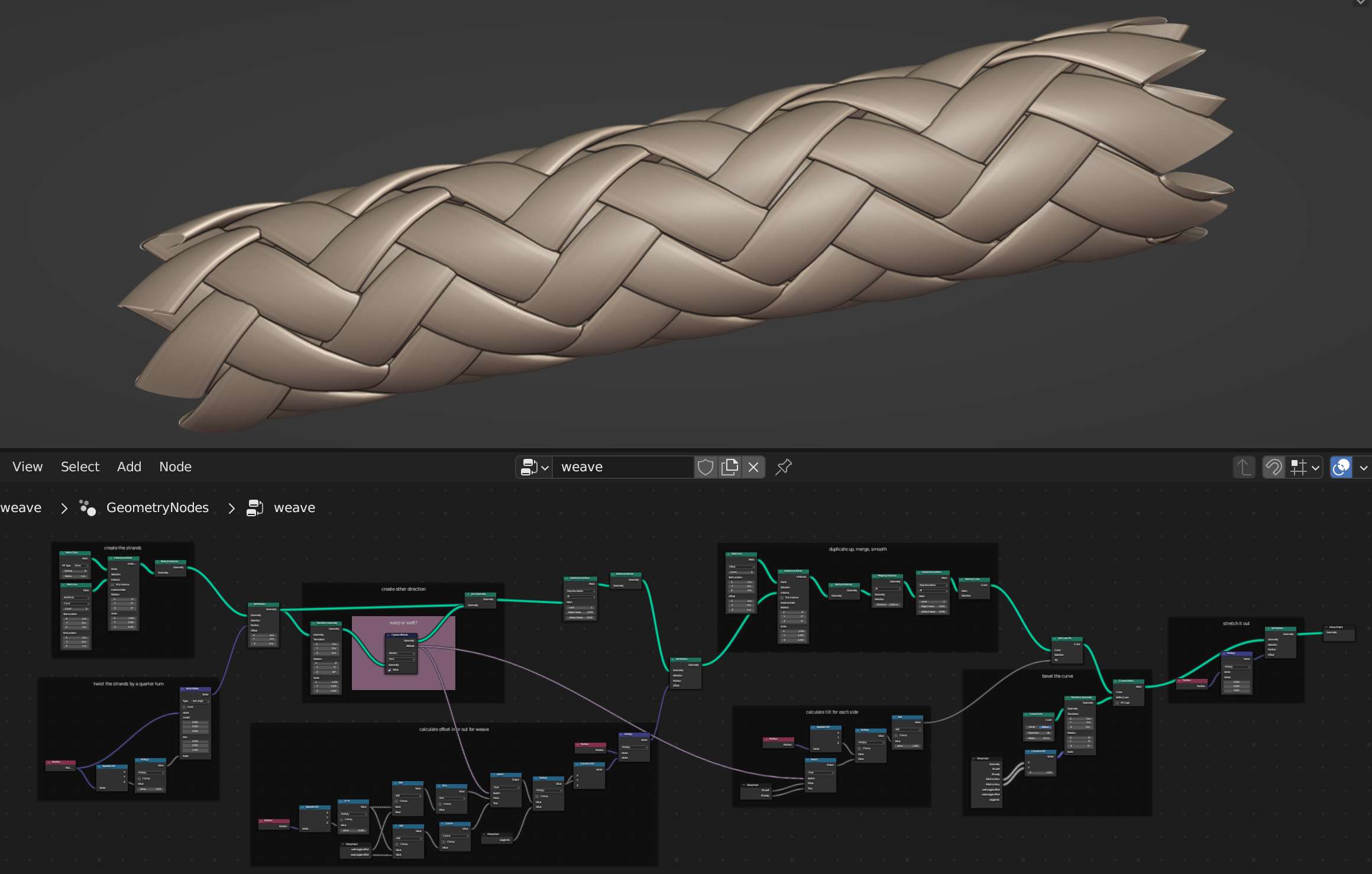
I used geometry nodes to create a woven sleeve of curves. This could be a good jumping off point to create the woven lance in the image you shared.
Create Strands
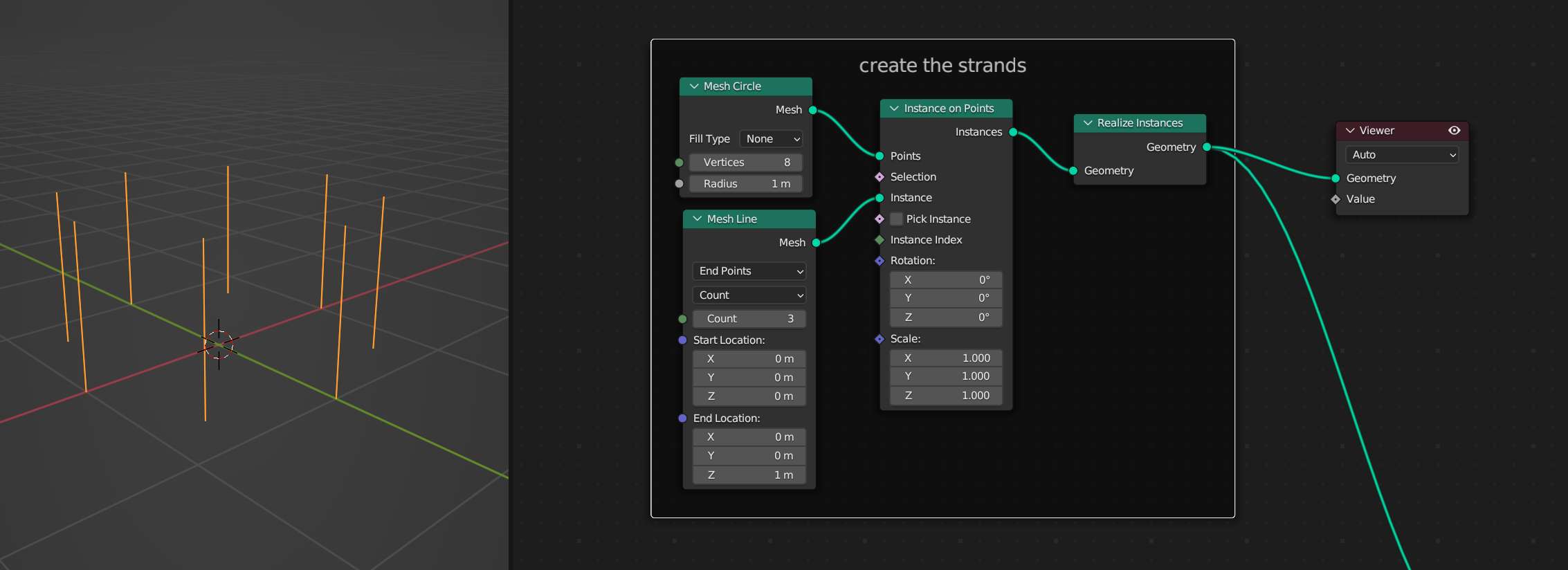
Start by creating eight strands. Each strand is a Mesh Line with three verts. The strands are instanced on a Mesh Circle with eight verts. Use a Realize Instances node to give the geometry of the strands.
Twist Strands By a Quarter Turn
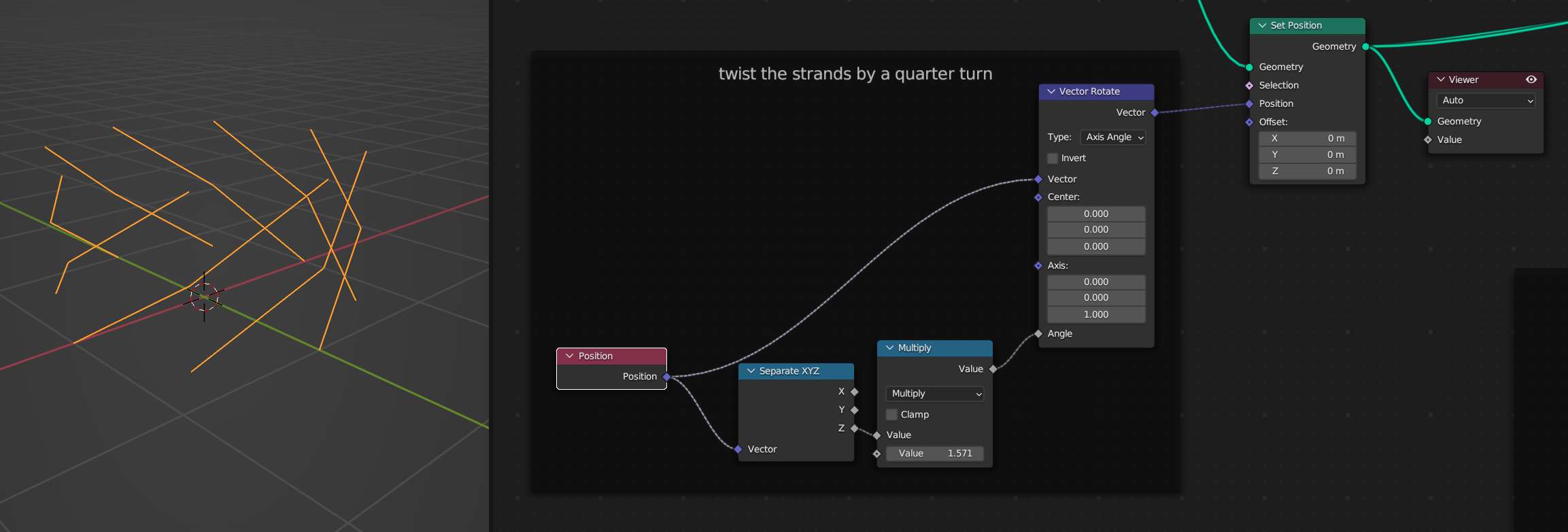
We want the tops of each strand to end up one quarter turn away from the base. Use a Vector Rotate node to rotate the Position attribute. Use the Z component of the position as a factor for the rotation. Our strands are one unit tall, so the quarter turn will be complete at their tops.
Note that rotations are in radians so a quarter turn is pi / 2 which you can type into Blender and it knows what you mean.
Create Opposite Direction
Create the strands for the opposite direction by using a Transform Geometry node with the X value set to -1.0. Give it some rotation too so that the new strands are offset from the original ones. Join the transformed geometry up with the un-transformed geometry. Also use a Capture Attribute node at this point to grab a boolean indication of which direction each strand is. Traditionally in weaving these directions are known as warp and weft.

Weave Strands with Trig Functions
Use Math nodes set to Sine and Cosine to wiggle the strands as they travel up the Z axis. The offset for the sine/cosine wave for each direction is controlled separately using a Switch node and the the warp vs weft indicator that we set up in the last step. These offsets require some tweaking once the whole structure is assembled to get the strands to actually look woven together.

Duplicate Up and Smooth
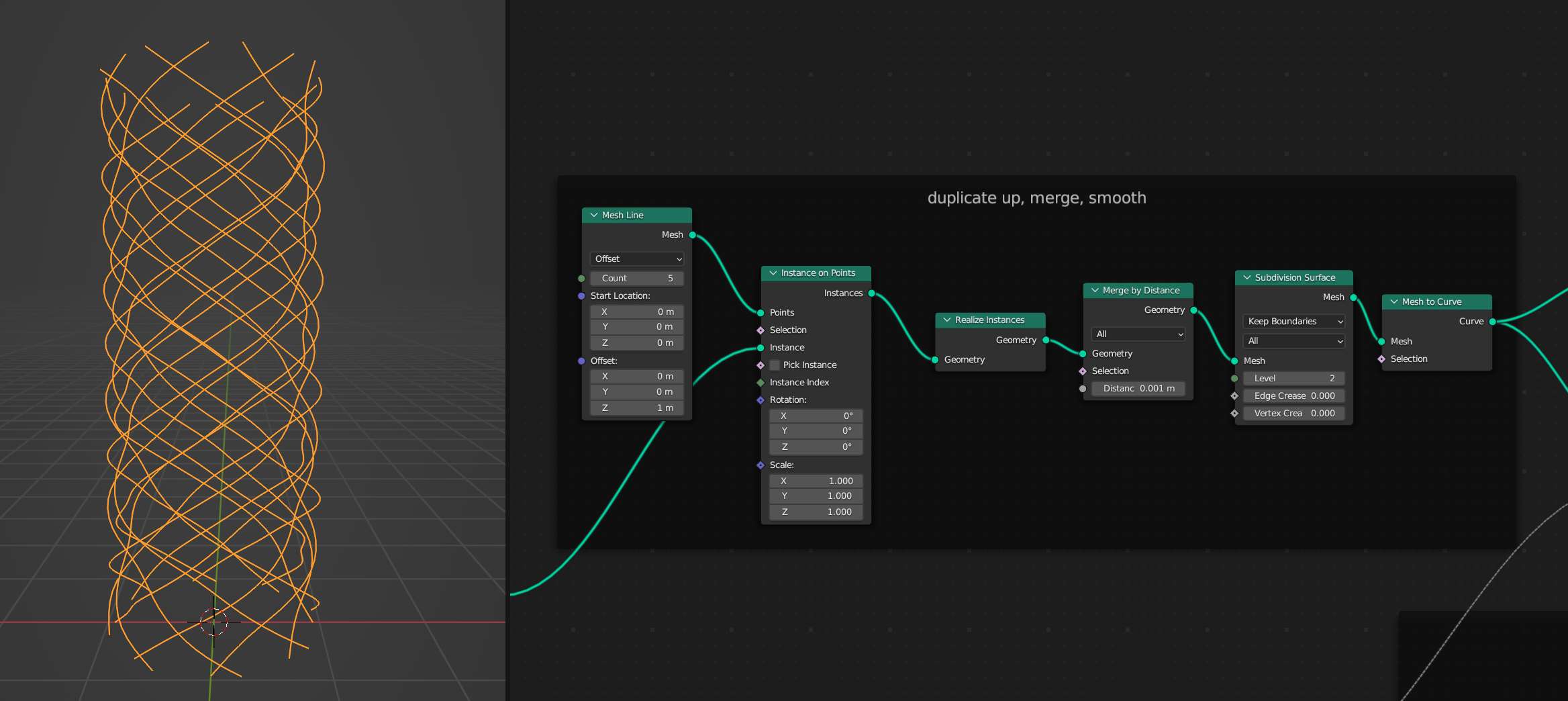
Up until now we've been working with one chunk of the sleeve. Use an Instance on Points Node to copy the chunk onto each vert of a Mesh Line.
Bevel The Curve
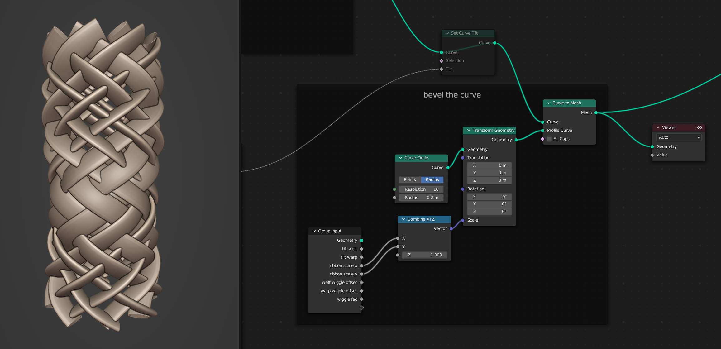
Use a Curve to Mesh node with a Curve Circle as the Profile Curve input to give the strands thickness. The Curve Circle can be transformed to make the strands look more like ribbons than noodles. You'll notice that the tilt is off at this point.
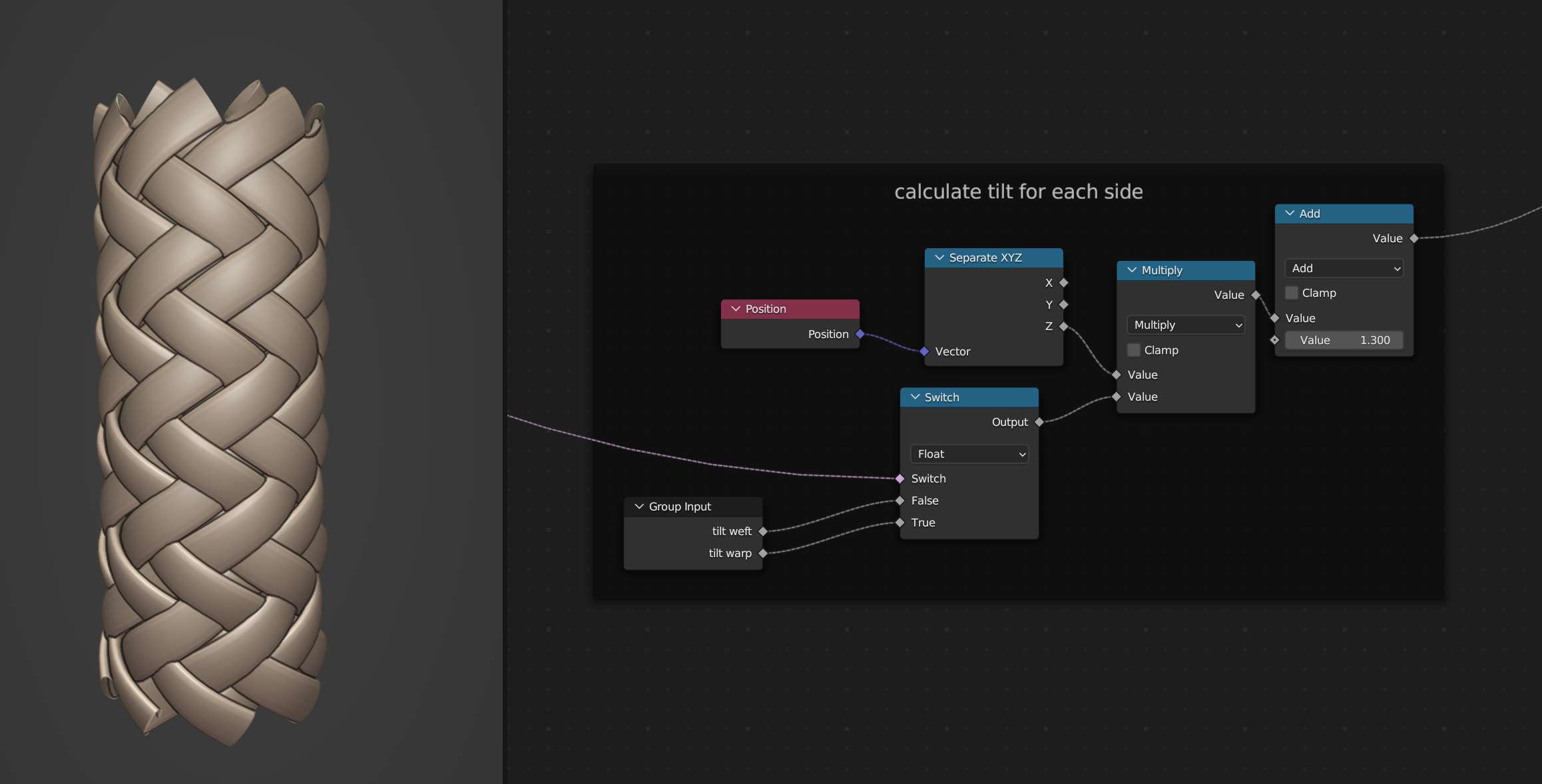
Set Curve Tilt
Use the Z component of the Position Attribute to set the tilt. This takes some tweaking to get it to look right. Use the boolean weft vs warp indicator that we set up earlier along with a Switch node to set the tilt for each direction individually.
Stretch
The weave in the reference looks a little more stretched so multiply the Z component of the Position attribute by some value to stretch the whole structure.
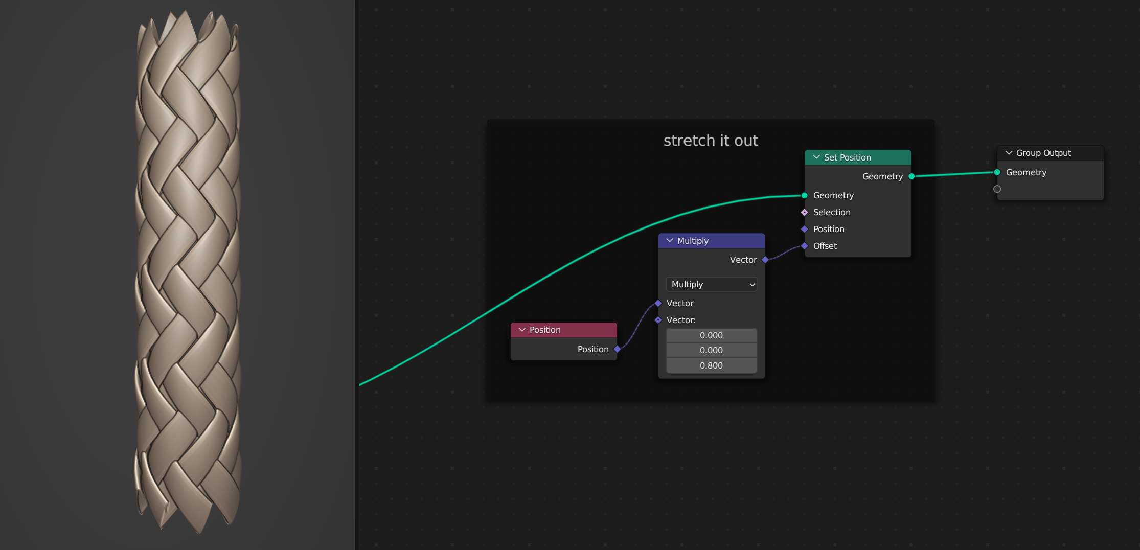
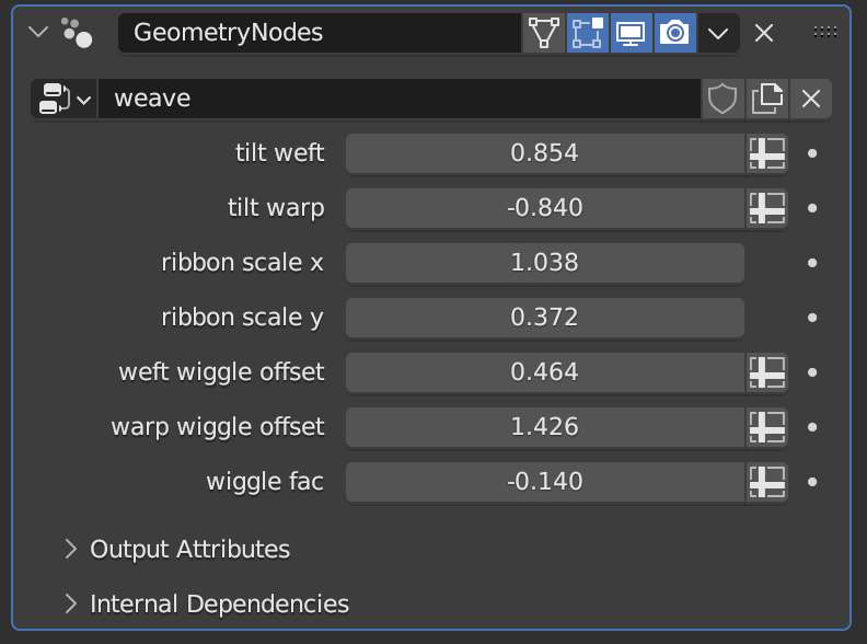
Here are the exact input settings that worked for me that aren't seen in the other screenshots.
