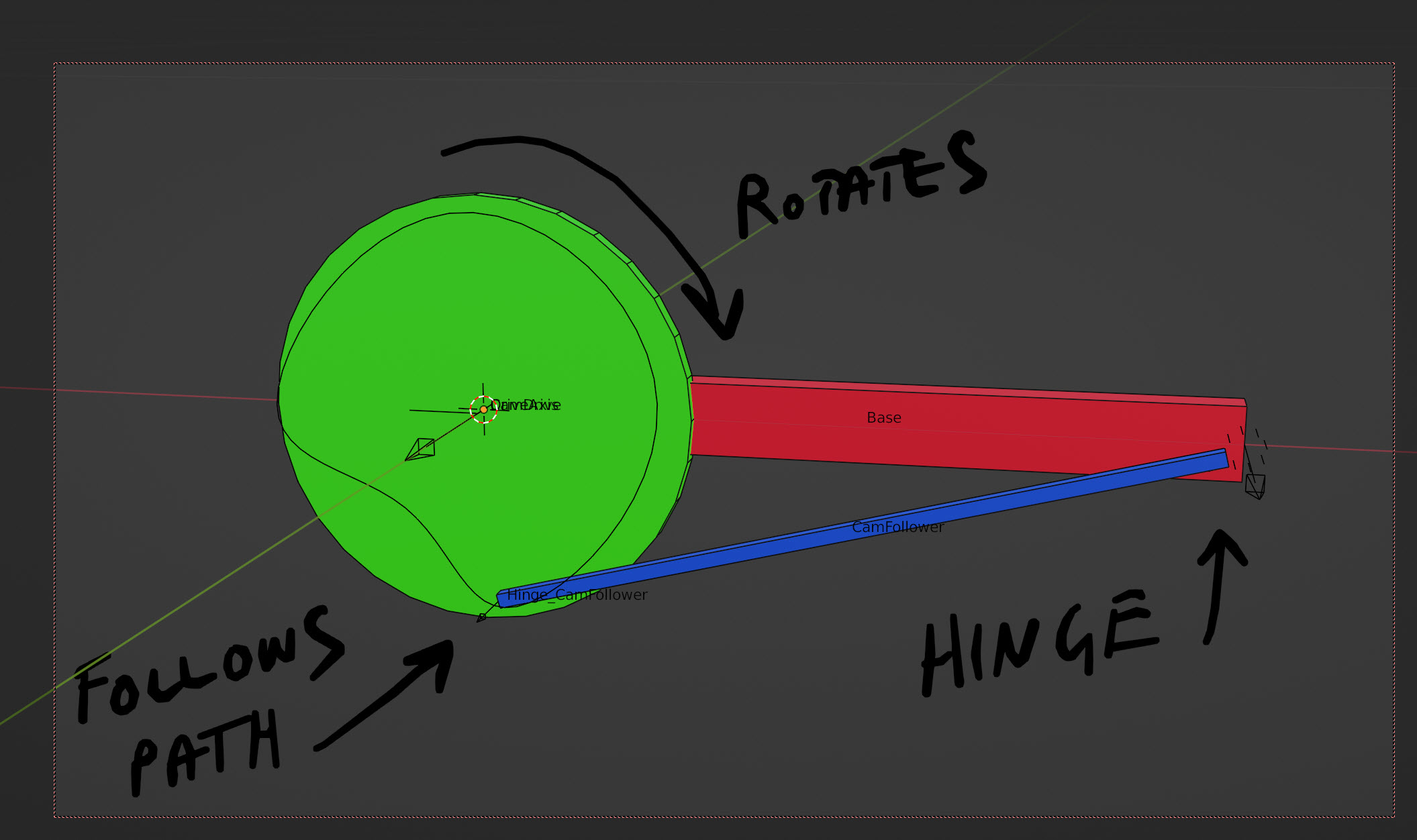
I'm using vers 2.77 and cannot load your Blend file. However I'm hoping this might solve your problem as the solution is fairly universal. You may need 2 cam & path followers depending on the toy horse.
You also mentioned physics would be required on some components, so it was attempted that way initially including a RB hinge constraint but inertia comes into it then and and some bouncing occurs at sudden cam changes. This is despite increasing the blue lever's mass and/or moving the RBC's point (empty) back from the lever. Blender after all is an animator and ideal for producing presentation video, but it's no engineering tool.
The solution below abandons the physics engine entirely and the end result is clean and reliable tracking.
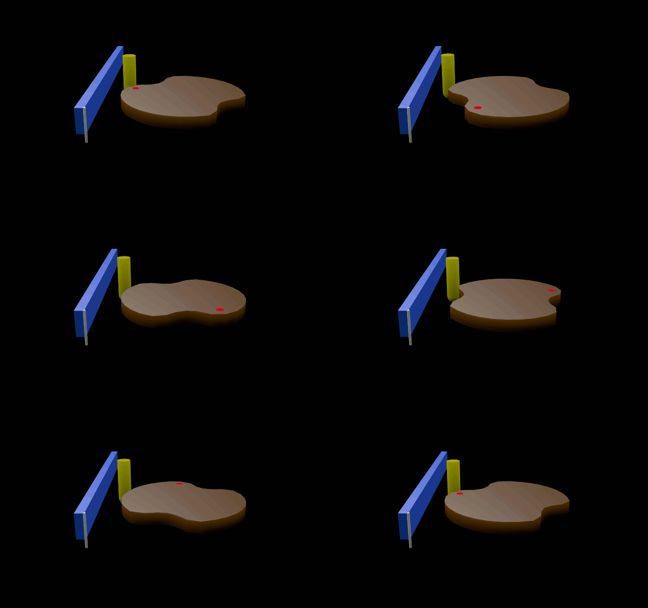
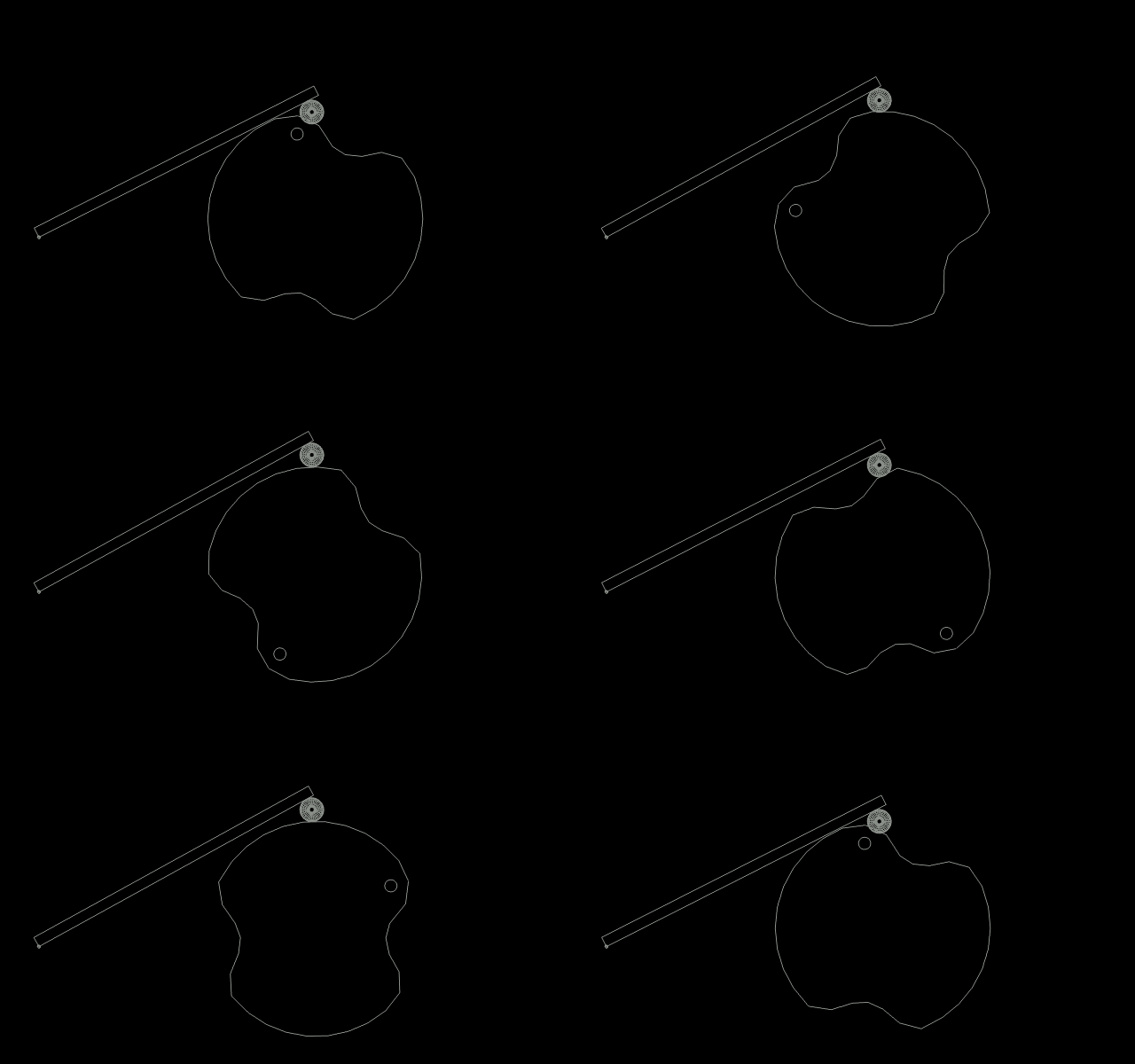
Note - there are 2 followers. an invisible rectangular Empty on the path itself and named 'Path Follower', and a 2nd, the yellow cylinder, named 'Cam-Follower'. It's easy to confuse the two.
The Path-follower (the original path object) follows the path's perimeter. The yellow Cam-follower, a cylinder, is parented to the former.
Because the (yellow) cam-follower's outer vertice is set as it's Origin Point, and that in turn parented to the invisible Path follower, (the rectangle Empty) the (yellow) cylinder is automatically held (more or less) against the cam-path's perimeter. See the last 2 pics below.
-==========-
From the beginning -
Shape the cam by deforming a mesh circle and convert it to a curve. Give it path properties.
With the cursor at the path's Origin Point, add an empty. Give it a 'Follow Path' constraint so it will travel around the path's perimeter.
Keyframe the path's rotation one full revolution. Give that 'Linear' interpolation. (more on that below)
When played the path-follower will want to track the cam's shape accurately, but as the cam (path) also has to rotate, things can get sticky.
The Empty will want to orbit some pivot point. Even when that's fixed, it may also deviate forward and back a little when encountering the cam's deeper contours.
The answer to both problems is to bake the (invisible) path follower's actions and -
Remove it's 3 'Rotation' strips in the Dopesheet.
Remove the Z axis & deviating axis' strips. (the X axis deviates)
As no scaling is involved, remove those 3 strips also, leaving just
the one Transform (Y) axis.
When played, all should return to normal with the cam and path-followers held to the one motion axis and tracking as they should.
As you no longer need the curve, it can be converted to mesh - That's done by firstly using a plane converted to a curve and that used to 'Bevel' the path. (cam) Beveling produces an accurately shaped rectangular pipe - a duct of sorts, and importantly with uniform thickness.
Scale the Bevel Plane and that will scale the duct uniformly until it's dimensions aren't bloated or too thin.
Convert that to mesh. (That's ALT-C for me)
It's inner (or outer) vertices are then removed so you end up with cam shaped walls but no top or bottom. (like a vertical cylinder without end caps) Go to Edit mode and fill those in.
You could try scaling that so it's up against the yellow cam follower but scaling can deform the shape and thickness some, so using the Graph Editor is recommended.
Simply bias the yellow follower's only remaining axis keyframes. (Select all keyframes in that axis (ONLY) and use G Y to drag them up or down so the follower is against the cam's walls)
That's about it for the cam follower and cam...
-===============-
As things stand some small tracking errors may still be apparent but mostly when viewed from the Top in Ortho Mode. Whether these errors are worth pursuing will depend on what it's for and the camera angle used. The graph editor's handles or additional keyframes will eliminate those.
Path Properties -
All evaluation keyframes should be Linear interpolation. This is also necessary for the path's rotation.
For absolute smoothness between last and first frames when looped, the path's rotation should be set to 360 degrees over the required number of frames + 1. (250+1 = 251)
The path's total frames should also be set to this. The final evaluation frame also. (keyframe the evaluation slot)
Play it at least once and step back one frame from the last. Keyframe that ROTATION angle in the 3D window.
Set the animation (or loop) end-frame to one less, (250) so frame 251 is never played.
-==============-
Making the blue arm lean against the the yellow cam-follower -
A single vertice on the (yellow) cam-follower's surface that's nearest the (blue) arm's surface is to be the parent for an Empty, and that in turn is used as a target for the lever arm to 'Look at'. ('track-to' constraint) That's what holds the arm (without bouncing) against the follower as though with a spring or gravity.
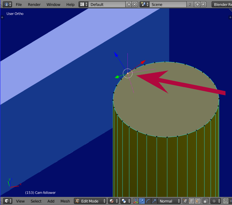
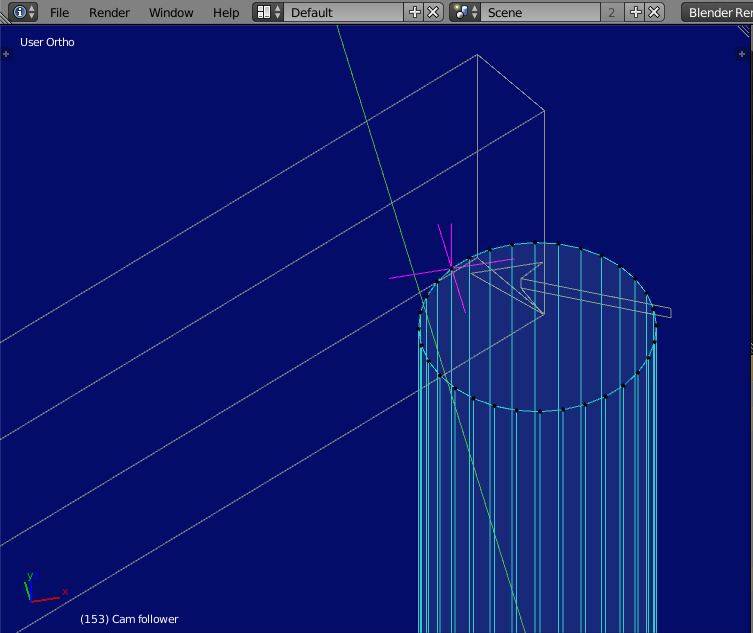
Note - the (blue) lever arm's origin point (hinge) is set to the same surface as that which sits on the (yellow) follower.


