In my current research, we are trying to create a 3D cow room/housing. Once the room is created, we are planning to place the blender camera (use it as a CCTV camera) in two different locations of the room. Our final goal is to calculate the total area the camera can capture compared to the total area inside the room. In this scenario, four walls and the floor will be considered to calculate the total area. Is it possible to do it in Blender?
-
$\begingroup$ the words 'calculate the total area' makes this quite the math puzzle. do you actually need to calculate the area or more just get a view of what the camera coverage would be like? to get a general idea of what a camera would see you would only need to know either the effective lens length ( a cell phone for example has a lens around 4.5mm but an effective length of around 28mm or the angle of view (described below) and the resolution of the camera ( you would enter that in your render settings so the camera represents the correct aspect ratio). $\endgroup$– ArthurCommented Jul 6, 2020 at 23:18
-
$\begingroup$ Here is what I would like to do - The camera will see a certain position of the room. For example, 90% of the floor, 100% of one wall, 75% of side walls (2), and 0% of the wall where it is mounted. Think about it as a CCTV camera coverage problem. By calculating (assume floor and walls have equal area), we can say it covered (.9+1+.75+.75+0)/5 = 68% of the total area. I need this number. I will manually provide the camera parameters (effective length, FOV, etc). $\endgroup$– SouravCommented Jul 6, 2020 at 23:30
-
$\begingroup$ Related blender.stackexchange.com/questions/61215/… $\endgroup$– batFINGERCommented Jul 7, 2020 at 16:17
4 Answers
Bisection using frustrum planes.
In the answer to this How to find all objects in the Camera's view with Python? @ideasman42 has written a little method to get the for planes of the camera frustrum.
For a simple room can utilize this to chop away any walls
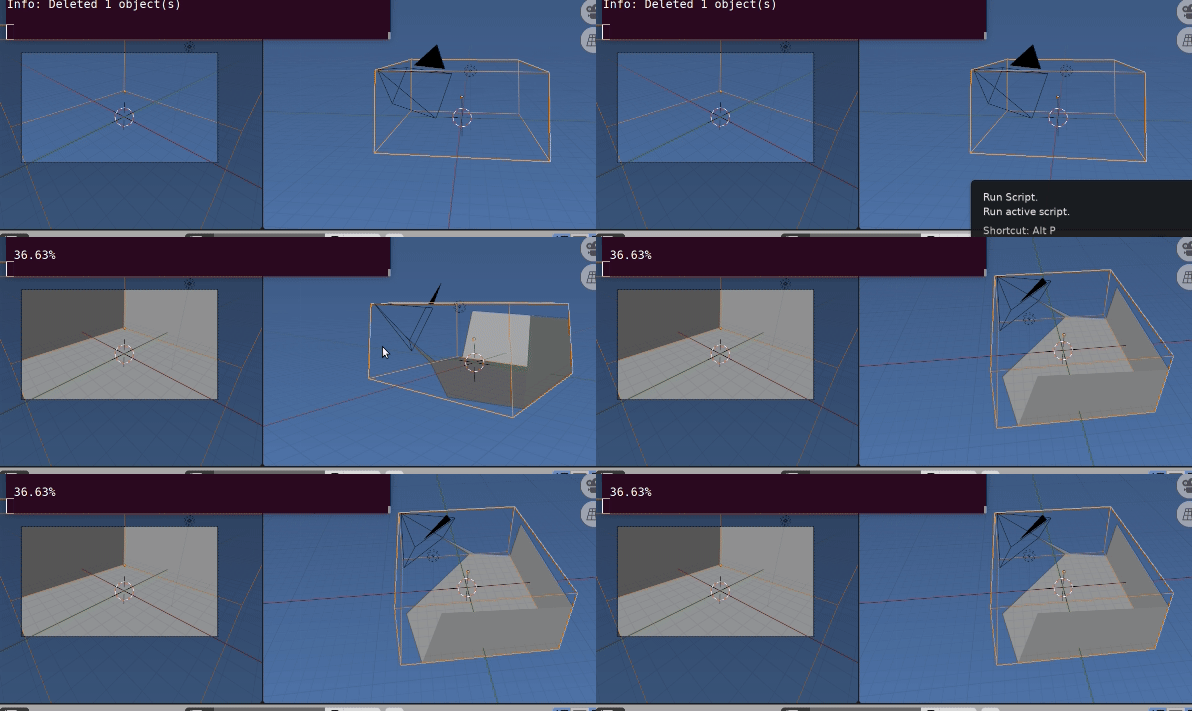
In gif above the wireframe box roof included is chopped to result and its percentage of originals face area printed to system console.
Script: Run in object mode with room as context and camera of interest the current active scene camera.
The mesh created after chopping and removing mesh outside is added to scene with global coordinates.
EDIT corrected for ortho camera.
import bpy
import bmesh

def camera_as_planes(scene, obj):
    """
    Return planes in world-space which represent the camera view bounds.
    """
    from mathutils.geometry import normal

    camera = obj.data
    # normalize to ignore camera scale
    matrix = obj.matrix_world.normalized()
    frame = [matrix @ v for v in camera.view_frame(scene=scene)]
    origin = matrix.to_translation()

    planes = []
    from mathutils import Vector
    is_persp = (camera.type != 'ORTHO')
    for i in range(4):
        # find the 3rd point to define the planes direction
        if is_persp:
            frame_other = origin
        else:
            frame_other = frame[i] + matrix.col[2].xyz

        n = normal(frame_other, frame[i - 1], frame[i])
        d = -n.dot(frame_other)
        planes.append((n, frame_other, d))

    if not is_persp:
        # add a 5th plane to ignore objects behind the view
        n = normal(frame[0], frame[1], frame[2])
        d = -n.dot(origin)
        planes.append((n, frame[0], d))

    return planes


context = bpy.context
scene = context.scene
dg = context.evaluated_depsgraph_get()
ob = context.object
camera = scene.camera
cloc = camera.matrix_world.translation

bm = bmesh.new()
bm.from_object(ob, dg)

bm.transform(ob.matrix_world)
total_face_area = sum(f.calc_area() for f in bm.faces)
for n, cf, _ in camera_as_planes(scene, scene.camera):
    bmesh.ops.bisect_plane(
            bm,
            geom=bm.verts[:] + bm.edges[:] + bm.faces[:],
            plane_no=-n,
            plane_co=cf,
            clear_outer=True,
            )

face_area = sum(f.calc_area() for f in bm.faces)
# comment out (or delete) 3 lines below for no new object
ob = bpy.data.objects.new("Test", bpy.data.meshes.new("Test"))
bm.to_mesh(ob.data)
context.collection.objects.link(ob)

# print result
print(f"{100 * face_area / total_face_area : 4.2f}%")
-
$\begingroup$ I have been trying to use this method but I am getting 0% regardless of the position of the camera. Is it possible for you to share the blender file? $\endgroup$– SouravCommented Jul 22, 2020 at 16:50
-
$\begingroup$ Long deleted. As an example, default scene, scale cube x 8 (so camera is inside), make sure cube is active (has context) run script. I get 10.34% $\endgroup$ Commented Jul 22, 2020 at 17:02
-
$\begingroup$ .. or if you have model of shed add blend to question. In example pic in question simply used cube object with camera inside. $\endgroup$ Commented Jul 22, 2020 at 17:15
-
$\begingroup$ It only works inside the cube. I tried to use the code by removing the roof plane. However, I am getting unexpected results (0.05%) and trying to figure that out. Thanks a lot $\endgroup$– SouravCommented Jul 22, 2020 at 17:35
-
$\begingroup$ it perfectly works now. However, I tried to place a cylinder between the cube and the camera to see if the area blocked by the cylinder excluded from the calculated total area or not. New area without the cylinder blocking the cube == new area with the cylinder blocking the cube. Do you think is there any way of excluding the area blocked by the cylinder? Here is the blender file - blend-exchange.giantcowfilms.com/b/ORX6OBZa $\endgroup$– SouravCommented Aug 4, 2020 at 16:23
All you need to know is the camera field of view in degrees, with that you can calculate the area, and distance to camera with basic trigonometry.
You could let Cycles do the job for you.
Set up the model of your room, and its camera.
- In Edit mode, edges, select all the edges and (Right-click >) make them all seams
- Give the room 2 UV maps : I've called mine 'Projection', and 'Areas'
- With the 'Areas' UV active, UV unwrap the room in an area-conformal way. Both 'Smart Project' and a simple 'Unwrap' seem to pass the test, for me.
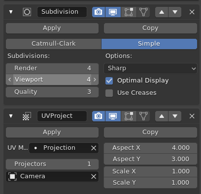
- Assign Subdivision (Simple) and UV Project modifiers to the model, with the Aspect Ratio of the camera entered in the UV Project.
Set up this shader: it colors the surfaces visible to the camera red, and the rest blue ...
Things to note:
- It's working in the 'Projection' UV space.
- The 'Compare' nodes simply set the condition that both the U and V are between 0 and 1 in the projection space
- There's a disconnected Image node, that we're going to bake to.
- There's an OSL script node. That means we will be rendering with Cycles, on the CPU, with the 'OSL' checkbox ticked.
(The multiply nodes are serving as logical ANDs)
The OSL node is there to detect whether shading points are a) in front of the camera, and b) not occluded by other surfaces in front of the camera:
shader Viz(
    output int viz = 1
)
{
    int isBehind(point pt){

        point c_pt = transform ("world","camera", pt);
        return ((c_pt[2] < 0));
    }

    if (isBehind(P)){
        viz = 0;

    }else{
         point camLoc = transform("camera","world", point(0,0,0));
         vector to_cam = normalize(camLoc - P);
         int hit = trace (P,to_cam);

         if (hit) {
            point hitpoint = (0);
            getmessage ("trace","P",hitpoint);
            viz = (isBehind(hitpoint));
         }
    }
}
When all is done, we get these views, from outside and through the camera:
Now, with the 'Areas' UV active, and that disconnected Image node we saw a while back active too, we can bake the Emission , as mapped by the 'Areas' UV. Only 1 sample is needed, so the bake is fast. This is the resulting baked image:
Now you can either use an external application, or this Blender script, to count the proportion of red pixels to red-or-blue pixels:
import bpy
import numpy as np

img = bpy.data.images['Coverage']
img_array =  np.array(img.pixels[:])
pixels = np.reshape(img_array,(-1,4))
n_rgba = np.count_nonzero(pixels, axis=0)
coverage = n_rgba[0] / (n_rgba[0] + n_rgba[2])

print (f"Pixels (rgba): {n_rgba}")
print (f"Coverage: {round(coverage*100,1)}%")
With this result:
-
$\begingroup$ I knew .. if you followed that one, you'd find a tweak or two! Thanks! Will correct. :D $\endgroup$– Robin Betts ♦Commented Jan 4, 2022 at 21:55
-
$\begingroup$ @vklidu late here.. will check tomorrow.. Are you sure it fixes that? I think the OSL only checks for visibility? I thought someone..Gorgious? came up with a magic solution for that distortion problem here , AFAIR, and I've been trying to hunt it down.. $\endgroup$– Robin Betts ♦Commented Jan 4, 2022 at 22:06
-
$\begingroup$ Ah sorry I felt an illusion it takes in calculation only faces visible to camera, but it takes also back faces ... hm sorry. $\endgroup$– vkliduCommented Jan 5, 2022 at 13:22
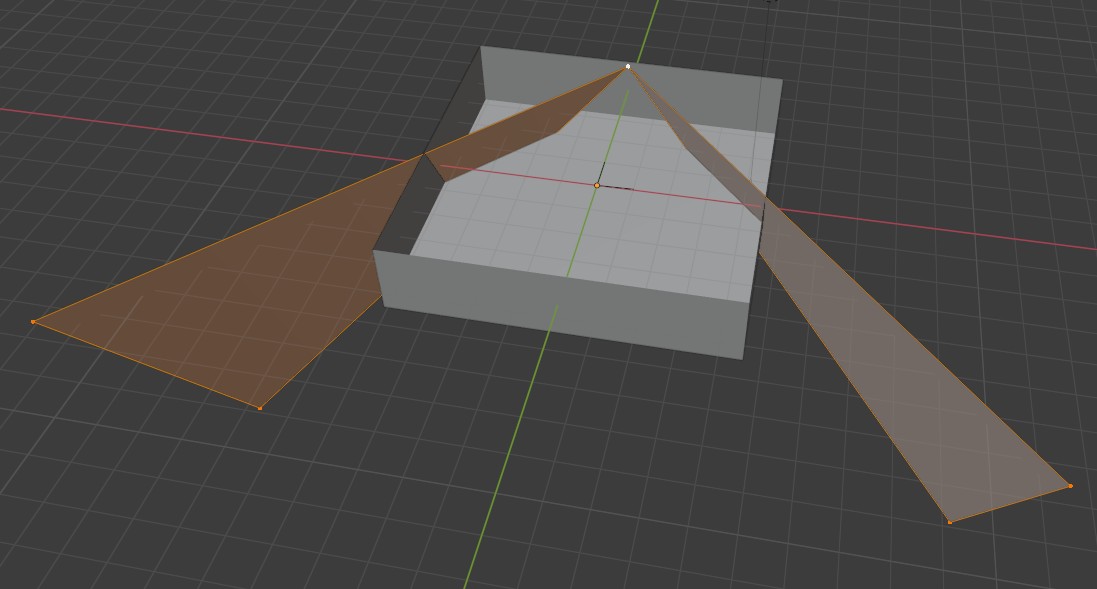
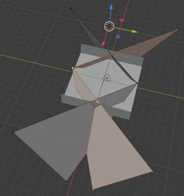
I am not sure how to get the exact number you are indicating you want. what I could do is make a visual representation. I took a four sided 'cone' and scaled the base to a standard 16:9 aspect ratio then raised the apex till it had an 88 degree angle of view (these specs came from a cosco camera) that angle is a best guess because blender is better with squares than triangles. I simply lifted/lowered the entire pyramid so the apex sat on a grid line and when rotating 44 degrees lined up with the grid I know it is very close (this is all done looking at the large side of the pyramid). then I deleted the base and two bigger sides leaving what represents the two vertical edges of the field of view. I have two screen captures with one and two cameras against the wall of the most basic representation of a room. as you can see in the image the floor coverage on the example is 100%.
the camera representations are set up with zero ceiling but tilted up they would probably cover the walls too. rooms that don't have full coverage will always have shapes left over that are not square and coming up with a number for such shapes is really up to knowing the Pythagorean theorem and doing the math.
the shape of the camera in the view port changes to this shape as well but has no side walls to intersect with the floor so would not work the same. I could have also left the bottom side of the view to better mark the field of view on the floor.


