6
$\begingroup$

TL; DR;

Using Sverchok, how might one construct a loft between edges that follows a defined path, as per figure 3 below?

Discussion

zeffii recently provided a nice demonstration of using Sverchok for Lofting between edges.

This was by way of augmenting an answer to a previous question (Sweep along a path through multiple cross-sections). However, I think that there was an aspect to that previous question that was glossed over in the answer, so I'd like to present it again here.

When constructing a loft object , it's sometimes useful to define a specific path that the loft is supposed to follow, and more convenient than defining edges all along that path - especially when the intermediate edges can be inferred from the start and end edge.

Once again, here's an example to illustrate the point...

enter image description here

Here, in each case, a circle morphs into a square. Figure 1. shows a simple transition from one shape to the other, and figure 2. shows a transformation that can be achieved using the solution zeffii provided in the link above.

The next challenge is figure 3. Constructing a loft between edges that follows a defined path.

Note that non-node-based solutions have been provided (e.g. Lofting between two different shapes along a path) but I'm all about those nodes.

$\endgroup$
1
  • $\begingroup$ for example: docs.mcneel.com/rhino/5/usersguide/en-us/html/… the Loft and Sweep are not issues we have nice succinct solutions for. Or this "modulated extrude" variation, it's a longstanding hole in our feature set. $\endgroup$
    – zeffii
    Commented Feb 4, 2020 at 16:08

2 Answers 2

6
$\begingroup$

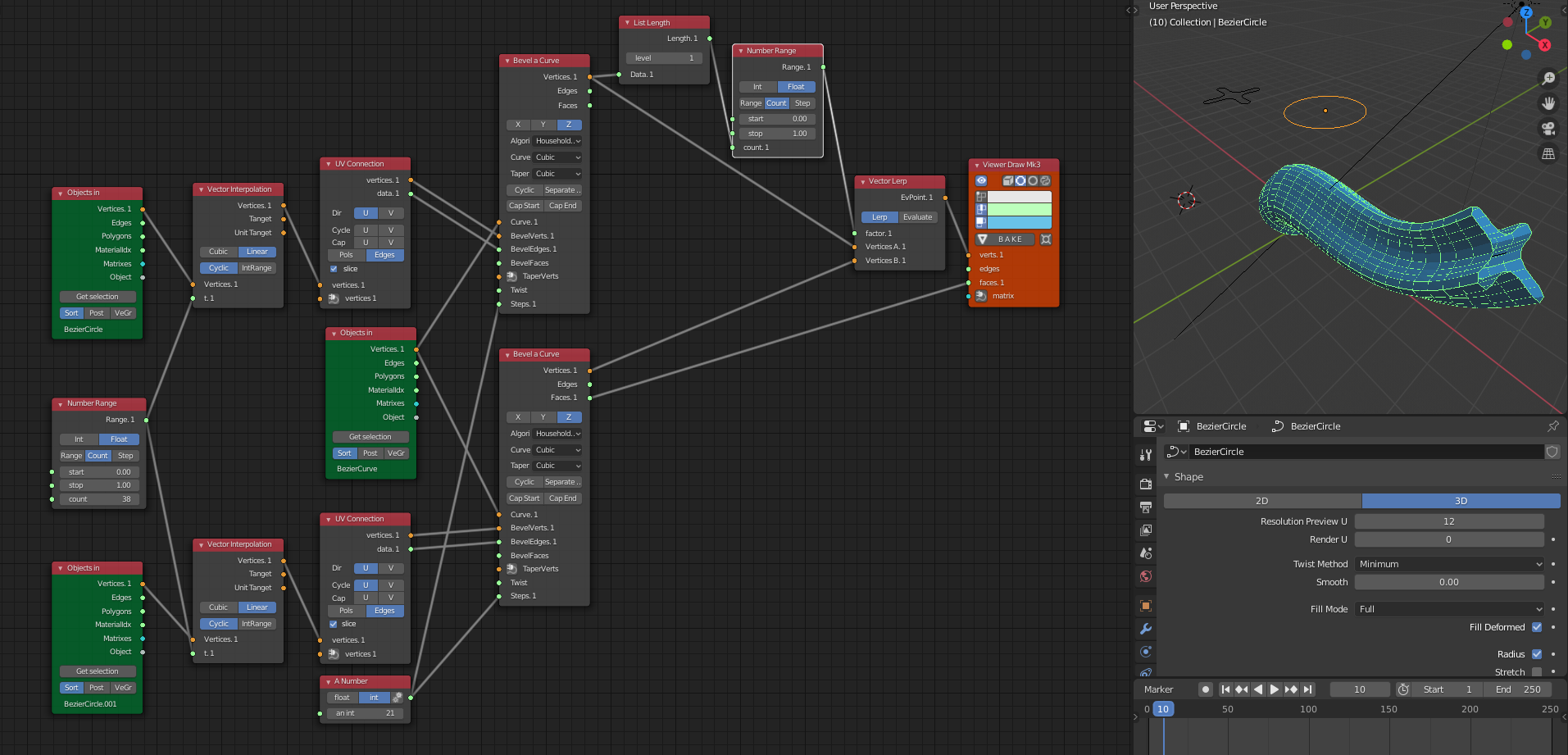
Here's another solution using Sverchok's own Bevel a Curve node (2 times).

(courtesy of Vic Doval from Sverchok Issue tracker)

enter image description here

A similar preprocessing step is employed.

  1. make the profiles match in vertex count and orientation
  2. interpolate between the two using the Vector Lerp node; taking its factor from a Range node. Notice the range node will output n unique values, so each vertex is uniquely affected. In my example I use the List Repeat to make sure every set of profile verts is uniformly affected.
$\endgroup$
6
$\begingroup$

I'm all about the nodes too, but i'm also all about leveraging the power of Blender from inside Sverchok. (When it makes sense, and when it can offer perfomance boosts.) This also offloads the pesky "twist" Matrix calculations to Blender, and lets you use the Twist parameter on the Trajectory curves.

For now i started a discussion about this on our Issue tracker, because I think this technique can be wrapped into a single node and automated/parametrized.

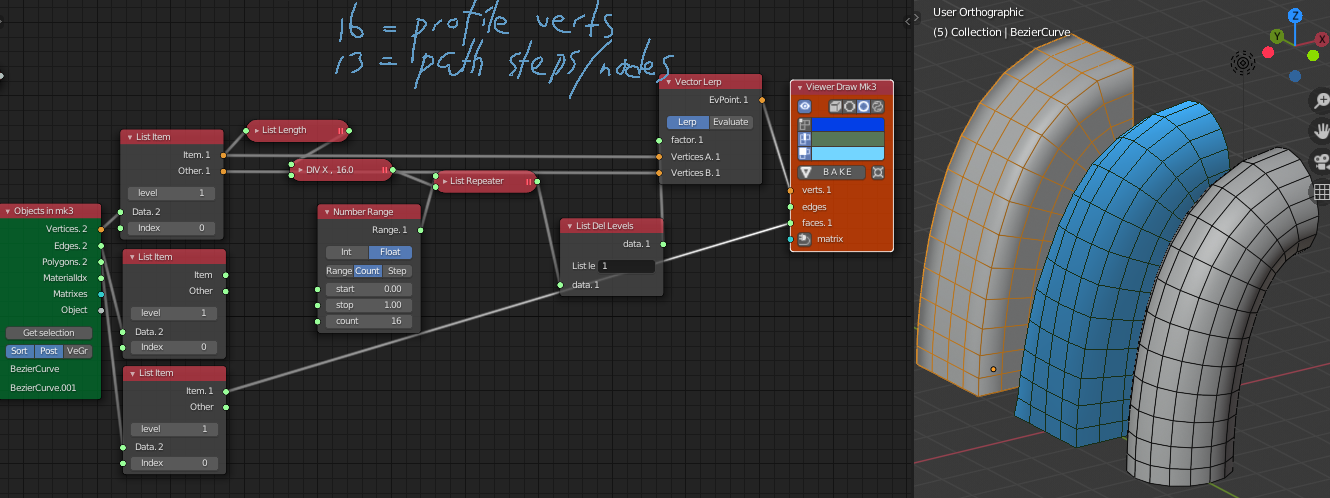
What I did here was generate two Profiles using generator nodes (Ngon, and Circle) and output them using the PolyLine Viewer, i also made sure the profiles had the same vertex count and the vertex positions aligned to allow nice linear interpolation between the two shapes. Then I added a trajectory and copied it, and added the two bevel shapes to them individually

enter image description here

then the Objects In node imports both Curve Objects as Meshes, we separate the two meshes, and divide each mesh by the number of vertices of the Profile vertex count. This division results in a number which corresponds to the number of nodes/vertices in the original trajectory Curves. It also is the number of times we need to repeat each element of our interpolation range. so we go from

[0.0, 0.07, ....1.0]

to

[  0.0,  0.0,  0.0,  0.0,  ...
   0.07, 0.07, 0.07, 0.07, ...
   ...   ...   ...   ...   ...
   ...   1.0,  1.0,  1.0,  1.0  ]

We do that with the List Repeat node, and List "Delete Levels" (which is essentially a "Flatten List" node)

here's the blend

$\endgroup$

You must log in to answer this question.

Not the answer you're looking for? Browse other questions tagged .