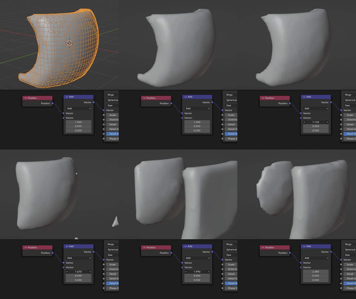
(Using Blender 3.6.8)
NB: to be continued - Documentation under work
Objective
To smooth a surface generated by a Volume to Mesh node, removing short wavelength features but preserving long wavelength ones.
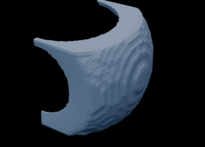
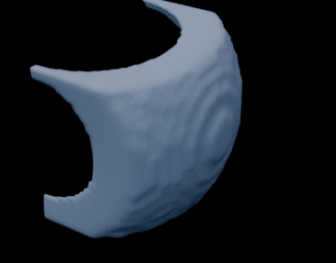
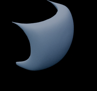
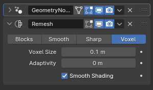
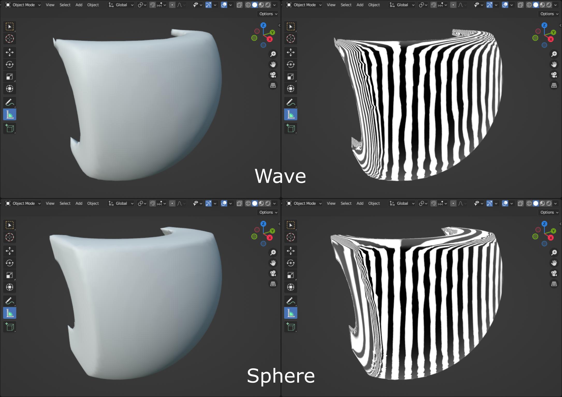
The following picture compares the achieved result from a Wave Texture node, to a reference surface corresponding to a thicken sphere, using the same voxel size. Left hand side pictures are rendered using Studio lighting set to outdoor with 35.5° rotation. Right hand side pictures are rendered using MatCap lighting set to reflection_check_vertical.
Approach
Assimilating voxels to sensors, a Sensor-Shift technique is implemented combining Volume to Mesh and Geometry Proximity nodes. Multiple surfaces of the same density field are generated using a Volume Cube node shifted by half the voxel size in different directions. These surfaces are blended to create the final result. It is to keep in mind that features smaller than the voxel size are not captured. As a sensor, the voxel behaves like a low pass filter. So shifting its position by half its size means that it is sampling the same information.
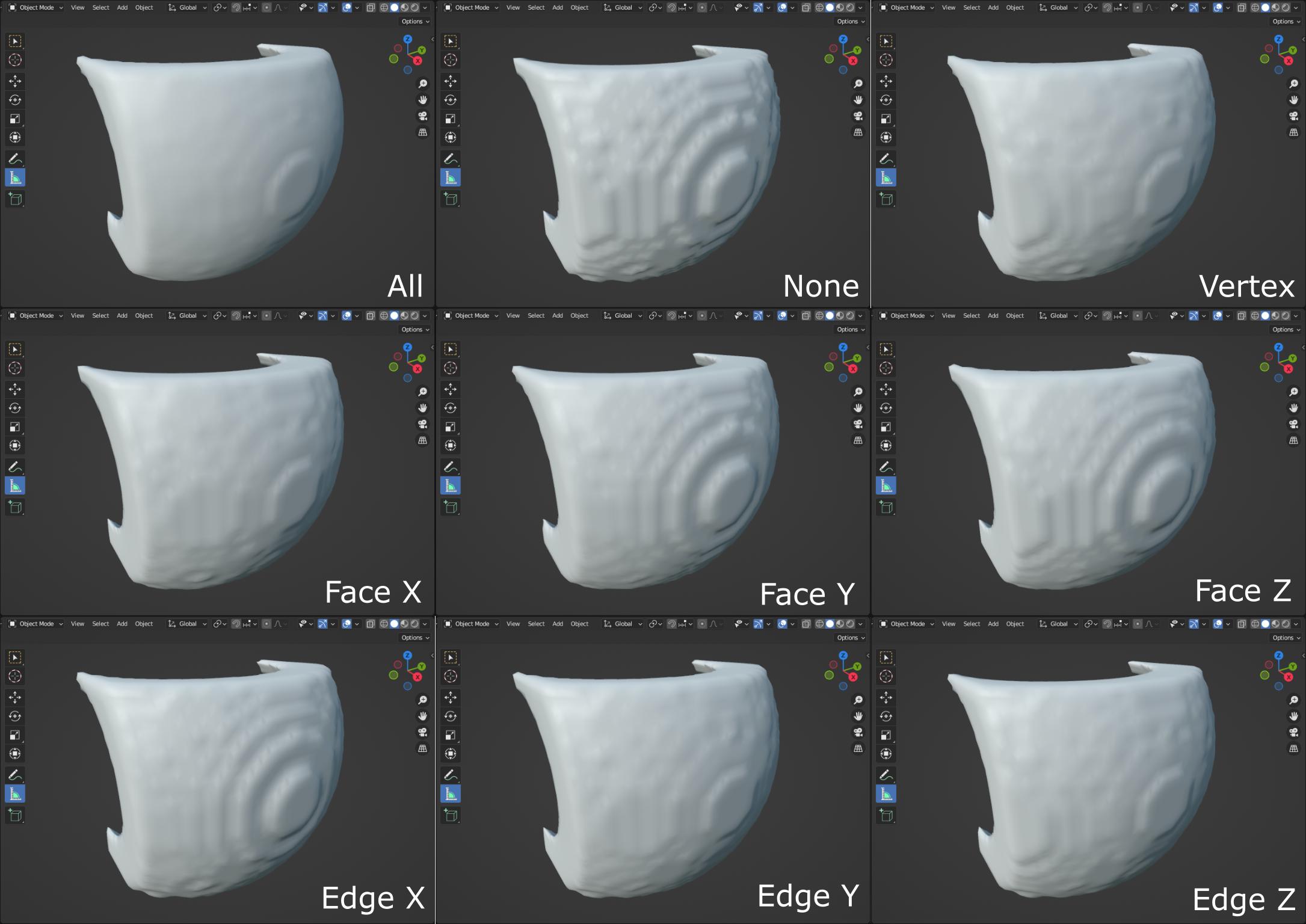
Using smooth shading, the following picture illustrates how each sampled direction is contributing to the final result labelled All, None corresponding to the initial sampling. Other pictures are achieved by blending this initial surface with a single new surface.
The solution labelled Vertex is achieved by moving new voxels to the vertices of the initial voxels. Even if it is smoother, this is not enough, particularly close to the lower left corner.
Solutions labelled Face are achieved by moving new voxels to the face centre of the initial voxels. Shifting in X direction contributes the most to the smoothing.
Solutions labelled Edge are achieved by moving new voxels to the edge centre of the initial voxels. Once again, shifting in X direction contributes the most to the smoothing.
Geometry Nodes Graph
To blend samples

1. The reference surface is generated without shifting.
2. This initial surface is projected to successive sampled surfaces. For very coarse sampling, it might help to smooth the vertices Position of this initial guess using a Blur Attribute node. But the original surface position must be preserved to blend with the others, through a Capture Attribute node.
3. The surfaces to blend count is initialized to 1.
4. Every combination of directions X, Y and Z is used as shifting. New positions computed by projecting the initial guess on the newly sampled surface are accumulated and the counter is incremented.
5. The final surface is computed by averaging all sampled directions.
6. Through the Group Input node, rendering is controlled:
6.1. Smooth: to display the initial guess or the blended surfaces.
6.2. Shade Smooth: to activate smooth shading.
6.3. Blur: to apply a post-processing smoother.
To sample

1. A surface is generated by shifting the sensor.
2. The vertices of the initial surface (i.e. without shifting) are projected on this new surface using a Geometry Proximity node with Faces as target elements.
3. Projected vertices position is accumulated in the field Position.
4. The projection-accumulation is triggered by a Capture Attribute node.
5. The counter of accumulated surfaces is incremented.
To capture snapshot

NB: To manage the voxels position, the origin of the coordinate system is shifted instead of shifting the sensor (i.e. the Volume Cube).
1. .
2. .
3. .
4. .
5. .
6. .
7. .
8. .
9. .
1. .
To compute density

1. .
2. .
3. .
4. .
5. .
6. .
7. .
8. .
9. .
1. .

1. .
2. .
3. .
4. .
5. .
6. .
7. .
8. .
9. .
1. .
Resources
Blender file: 

