1
$\begingroup$

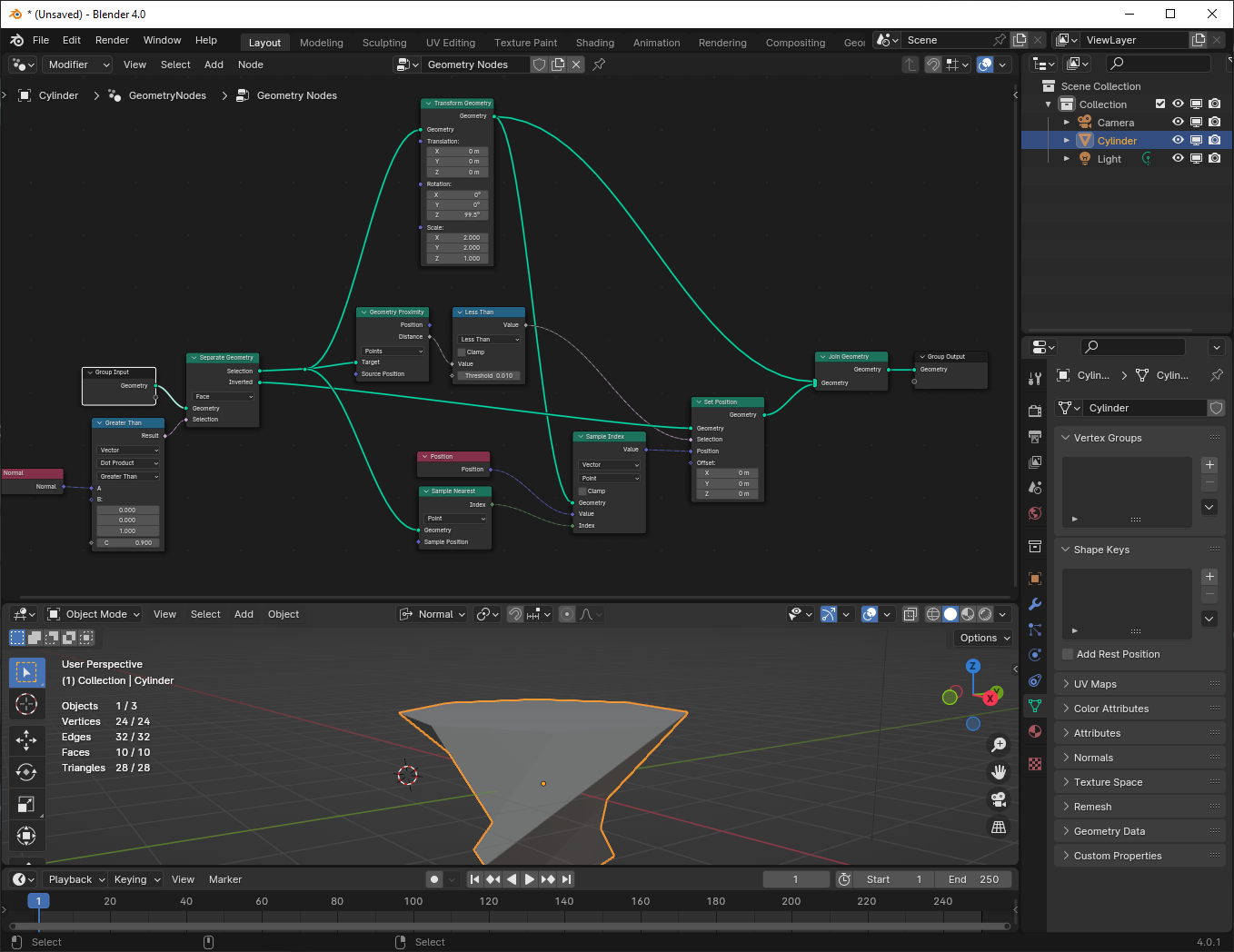
imagine you have a shape in which, one part is separated, and when the separated part deforms, the rest of the shape follows.

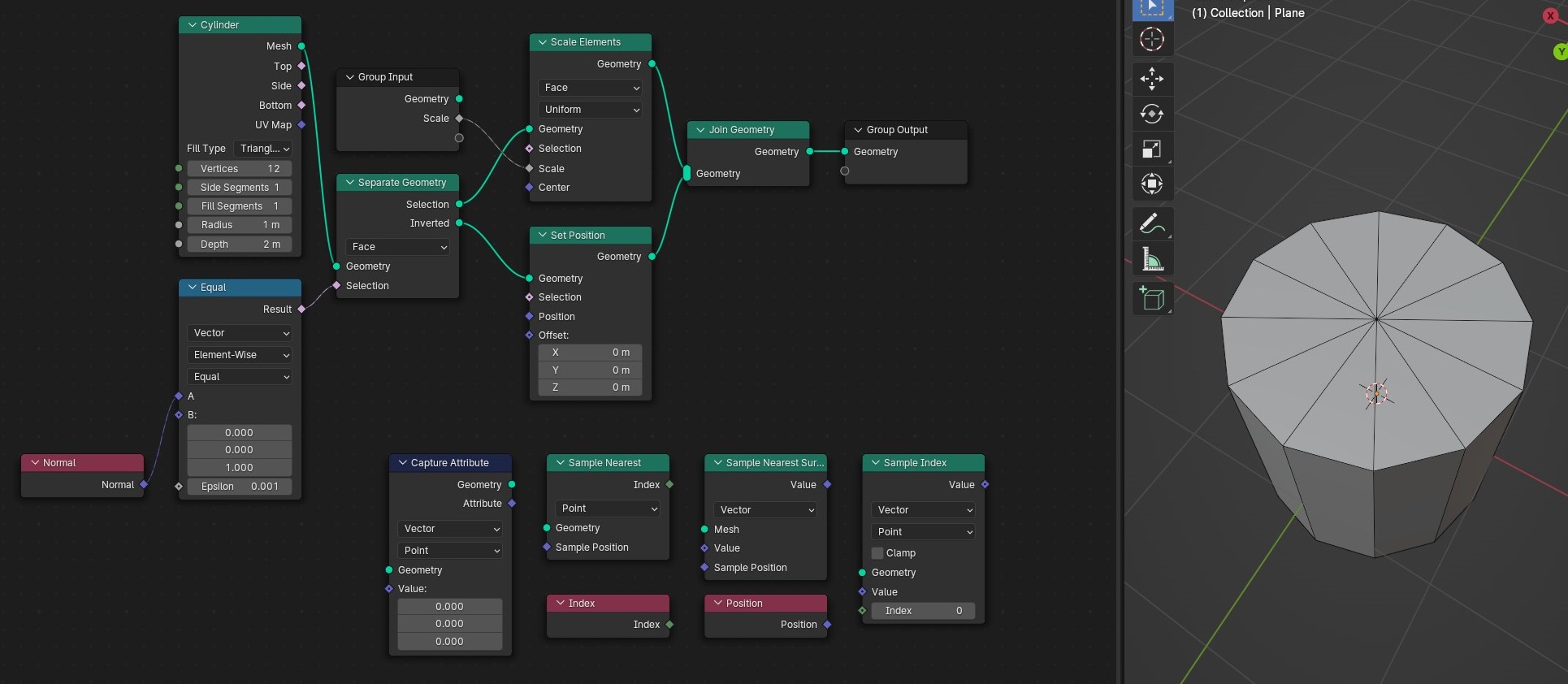
what I have:

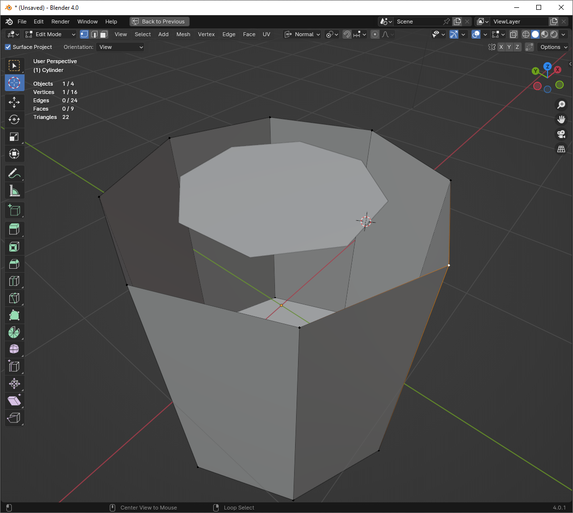
enter image description here

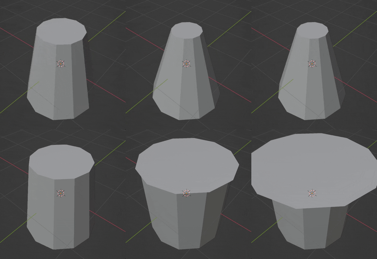
what I want:

enter image description here

enter image description here


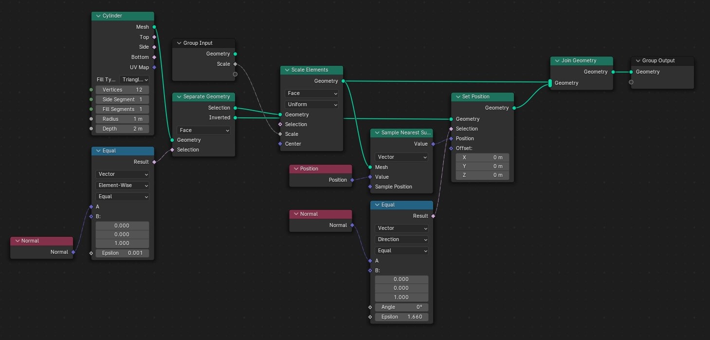
Edit 01

by adding a sample nearest surface, it works when scaled down, but it won't work when scaled up.

enter image description here

enter image description here


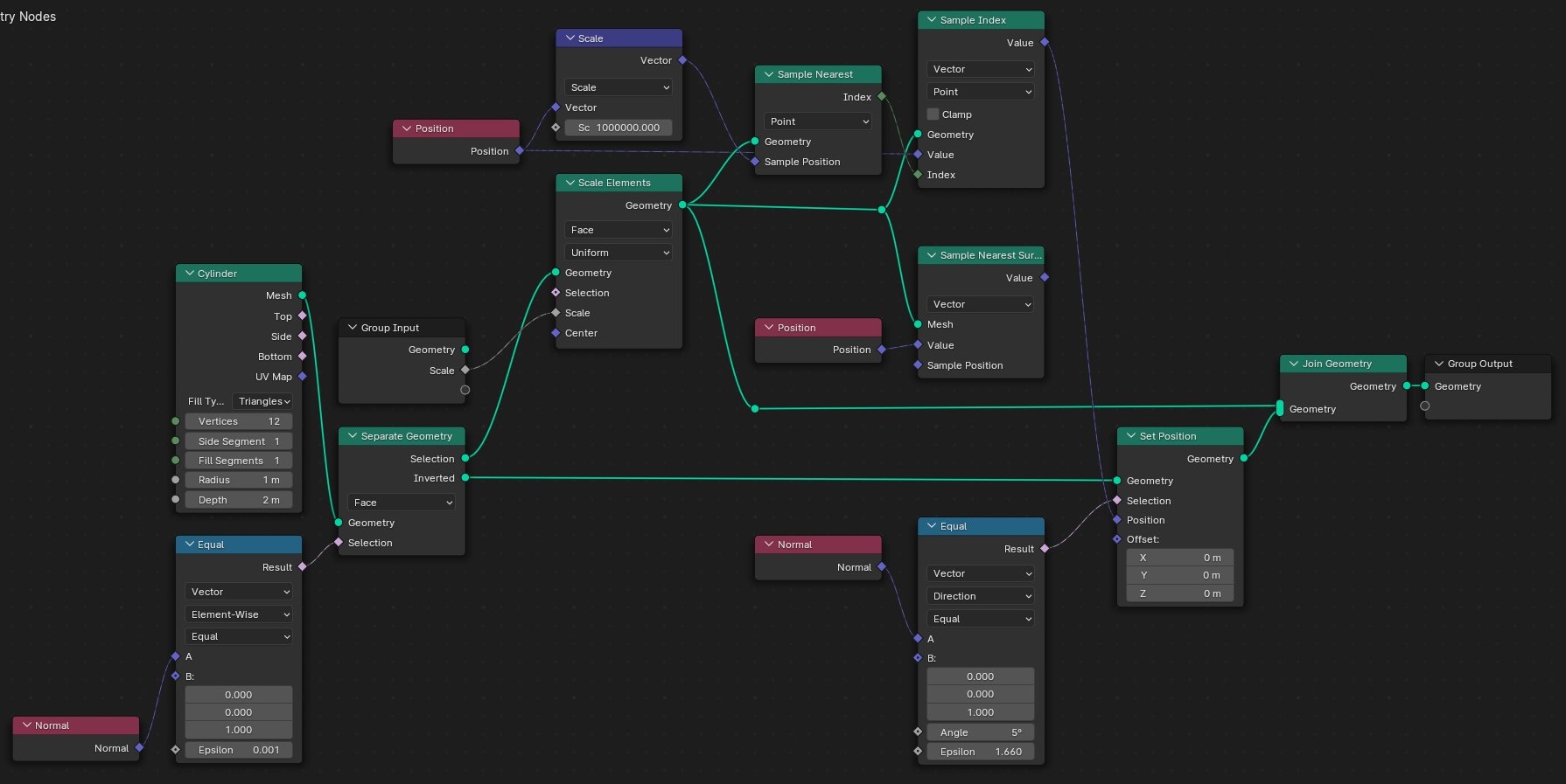
Edit 02

with these nodes, it works fine, can you explain why ? is it a correct answer ? why the math node needed!?

enter image description here

$\endgroup$
15
  • $\begingroup$ Just scale the top face first, and then separate it (if needed). ...or is it a more complex scenario than shown? $\endgroup$
    – quellenform
    Commented Dec 5, 2023 at 0:13
  • $\begingroup$ scale was just an example. I need a way that the shape follows the separated part in any operation(move, rotate, ...). $\endgroup$ Commented Dec 5, 2023 at 0:17
  • $\begingroup$ Could you convert the perimeters to curves and loft them ? $\endgroup$
    – Robin Betts
    Commented Dec 5, 2023 at 8:41
  • $\begingroup$ @RobinBetts I don't know, because this GeoNode may use on different kinds of meshes. $\endgroup$ Commented Dec 5, 2023 at 8:55
  • 1
    $\begingroup$ @RobinBetts I have some GeoNodes, (like solidify, extrude evenly...) that when I use their selection socket won't work properly, but when the mesh is separated they work fine. $\endgroup$ Commented Dec 5, 2023 at 9:09

2 Answers 2

3
$\begingroup$

by adding a sample nearest surface, it works when scaled down, but it won't work when scaled up.

It is sampling the nearest point on the surface. When that surface is scaled down, the nearest point on that surface is the perimeter of the surface. But when it is scaled up, the nearest point is exactly where it is when it's not scaled up.

Here, let's consider a slightly different situation:

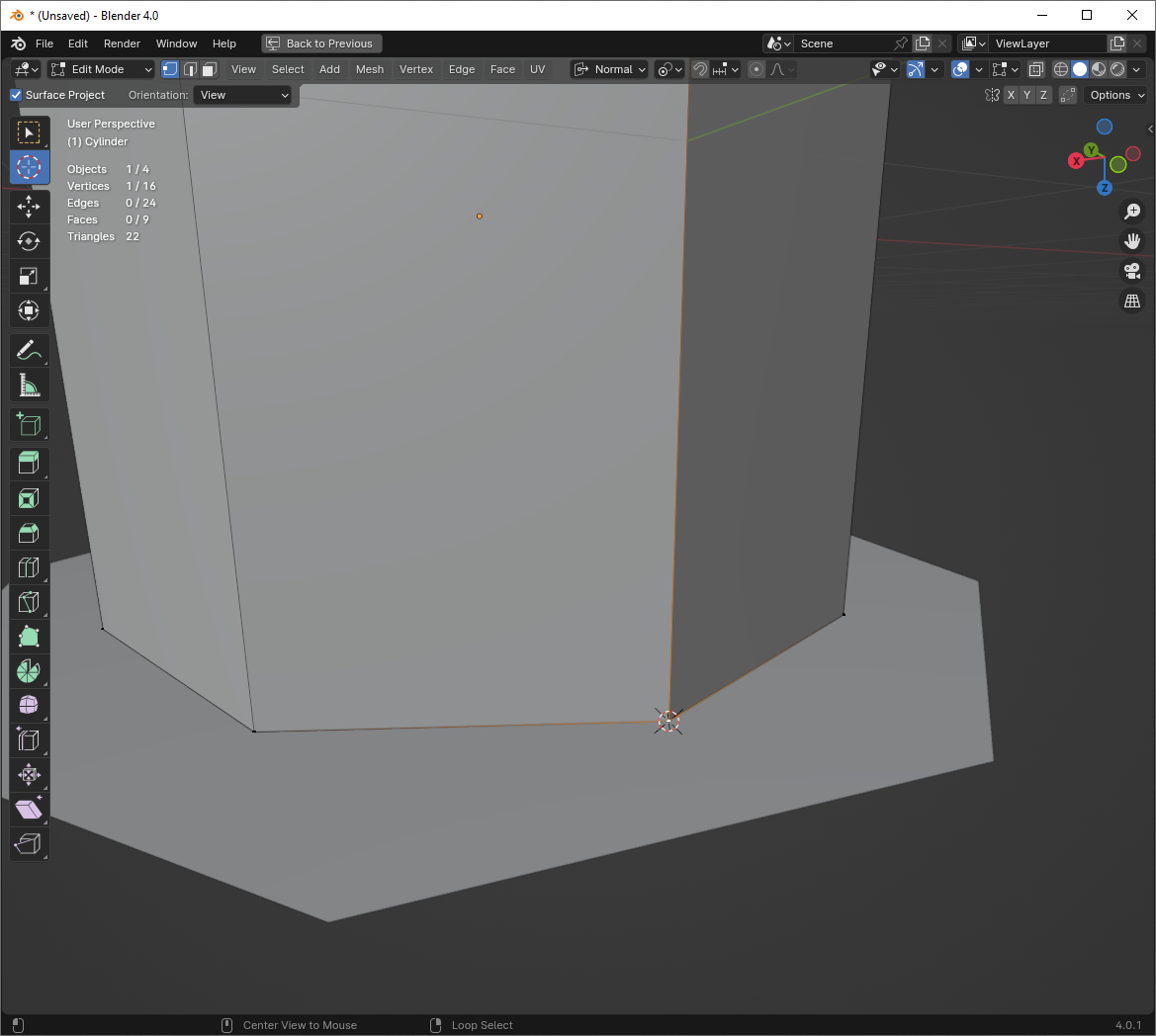
enter image description here

This is similar to what your GN is seeing at the time of sampling the nearest surface. (The difference is that I have both rotated and scaled the target we're sampling so we don't get confused by vertices.) What is the nearest position to the selected vertex on that surface? It is at the location of the cursor.

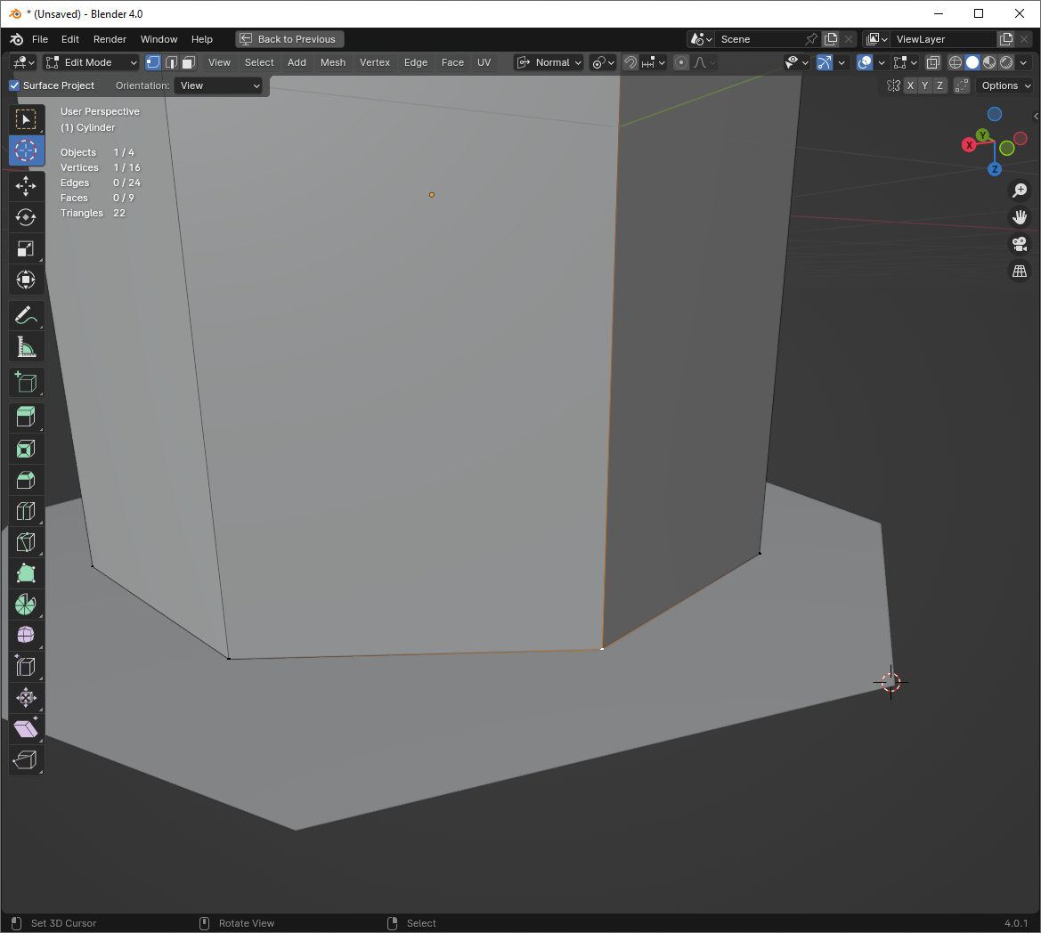
Let's scale it up and look from underneath now.

enter image description here

Now, what is the nearest position on the new surface? There happens to be surface right where the vertex is! The distance to surface is zero. The nearest surface position is right where the vertex already is.

with these nodes, it works fine, can you explain why ?

The reason this second group works has nothing to do with any math nodes. It works because you are no longer sampling the nearest surface, but the nearest point instead. Going back to what I've had before, now what is the nearest point on the target?

enter image description here

The nearest point is at the location of the cursor. It is the location of the nearest vertex on the target. Not edge, not surface.

is it a correct answer ?

Whether it is a correct answer is always going to depend on what you want it to do. For the example you've given, where the face only scales about its center, and is always an ngon? Yes, it is a valid answer.

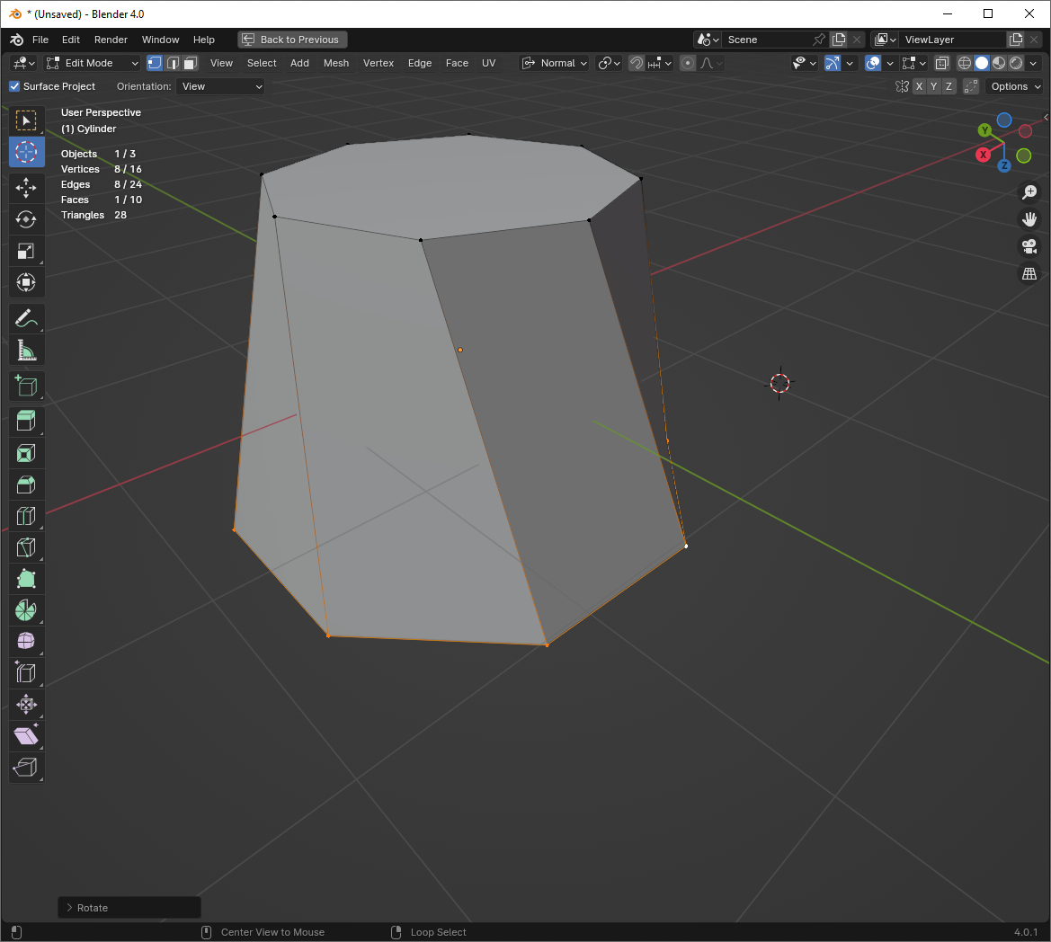
But what if you want to rotate the face as well? Well, do you want this as your output?

enter image description here

Then it's the right answer. Unless you want it to interpolate smoothly through animation, which this won't.

When using GN, you do the least you can, to achieve what you need. Otherwise, you end up with a monstrosity. But for arbitrary transformations, we're often going to be establishing a correspondence between two vertices so that transforms to one can affect the other. This correspondence can exist in a lot of different ways-- for example, one can use shared UV coordinates to create that correspondence. But another way to create that correspondence is via indices:

enter image description here

In this case, I am storing the index of the nearest point before I transform that point (here, by both rotation and scaling). Then, after the transform, I can use that stored index to get the location of the nearest point from before that transformation. This allows me to maintain the relationship even through sharp rotations, something I couldn't do if I was just sampling the nearest point-- otherwise, the nearest point would be some other vertex, not the one that was originally in the same location.

$\endgroup$
1
  • $\begingroup$ thank you, that was a very in-depth explanation and easy to understand. $\endgroup$ Commented Dec 5, 2023 at 19:58
4
$\begingroup$

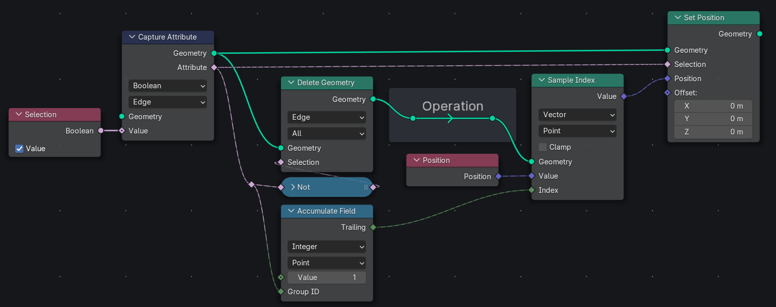
Separate geometry with index transfer

Main Concept

If the geometry was originally connected, then there is a way to precalculate the indices needed to transfer attributes including the position from one part to another.

For this we will use the ‘Accumulate Field’ node. What this node does is just addition iteratively through a group of points. We could take advantage of the way Indices (Index plural, so the ‘Index’ node) get recalculated when geometry gets removed, and the order in which the ‘Accumulate Field’ node iterates through elements when doings its addition.

A meshes Indices are always numbers going from 0 and ascending till it reaches the last element (which will be $n-1$), and there can’t be missing numbers in-between; So when geometry is removed, which would now cause gaps in the numbers (meaning skipping numbers), blender will recalculate them (or more condense them). The way the Indices end up is actually the same order, but now all consecutive numbers starting from 0. So:

Initial/Potential Indices: 0 1 4 5 7 9
Final/Actual Indices: 0 1 2 3 4 5

Now, the 'Accumulate Field' node counts (Iterates) in the order of the Indices.

Index: 0 1 2 3 4 5
Value: 5 9 6 8 4 1
Accumulate - leading: 5 14 20 28 32 33

Here I just shuffling the Indices to show the point:

Index: 5 4 1 0 3 2
Value: 1 4 9 5 8 6
Accumulate - Leading: 33 32 14 5 28 20

The ‘Accumulate Field’ Trailing starts at 0 and then starts counting up - basically everything is pushed off one, which is perfect for counting Indices.

For us to calculate what the new index is going to be once the geometry is separated, all we have to do is set a Group ID (this is just a selection) of what the new geometry is going to be and accumulate over it, and it will condense the Indices to range.

Index: 0 1 2 3 4 5 6 7 8 9
Value: 1 1 1 1 1 1 1 1 1 1
Group ID / Selection: 0 0 1 1 1 0 0 1 1 1
Accumulate - Trailing: 0 1 0 1 2 2 3 3 4 5

Implementation Differences

When could you even use this generated Index? In the case of separating vertices for example only one of the outputs of the separate geometry will have those vertices, do in that case knowing its Index is pointless, because you already know it from the ‘Index’ node, and the other part of the separated geometry doesn’t have that geometry and thus doesn’t have the Index you calculated…

The Only case of shared geometry is when separating faces, because both sides have the vertices and edges that were the same on the original mesh [I’m only going to be discussing vertices is the demonstration, because you set position on vertices, but this could be done for other elements as well].

There is another way of doing this, where you use a ‘Delete Geometry’ do separate some part of the mesh, and then transfer some attribute(s) back to the original mesh. This could be done when separating any type element and on any domain.

[Advantage to this method

  • There is you need to rejoin and merge the separated elements, since you are just transferring it back to the original mesh.
  • There is no need to capture the selection or idex etc. ]

Node Implementation

In the case of separating faces. The boarder vertices are included in the group of whatever side you are transferring from. You could easily get the boarder vertices with the ‘Face Group Boundaries’ node, and add (or subtract) them to the Group ID.

enter image description here enter image description here Here are illustrations of sampling in both directions.

In the above two Figures you could see that I used the boarder selection as the selection, since that is the part of the mesh that the ‘Index’ does and could map to correctly [it is the only shared geometry].

Here are illustrations the ‘Delete Geometry’ method: (I don't think the 'Capture Attribute' nodes are necessary the illustrations below)
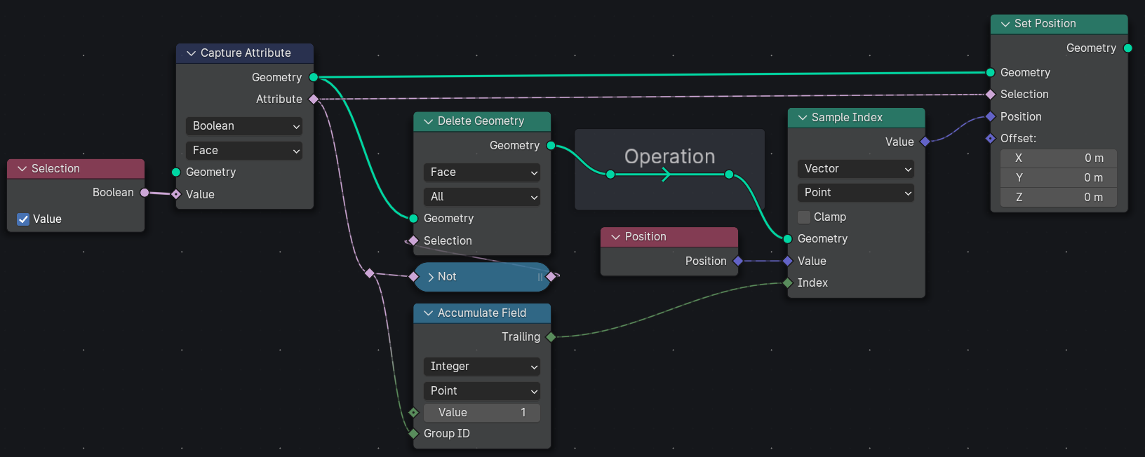
enter image description here enter image description here The difference is in the ‘Delete Geometry’ (and ‘Capture Attribute’) domain.

Here is a pretty cool example where you smooth the boarder vertices of a (selection on a) noise texture:
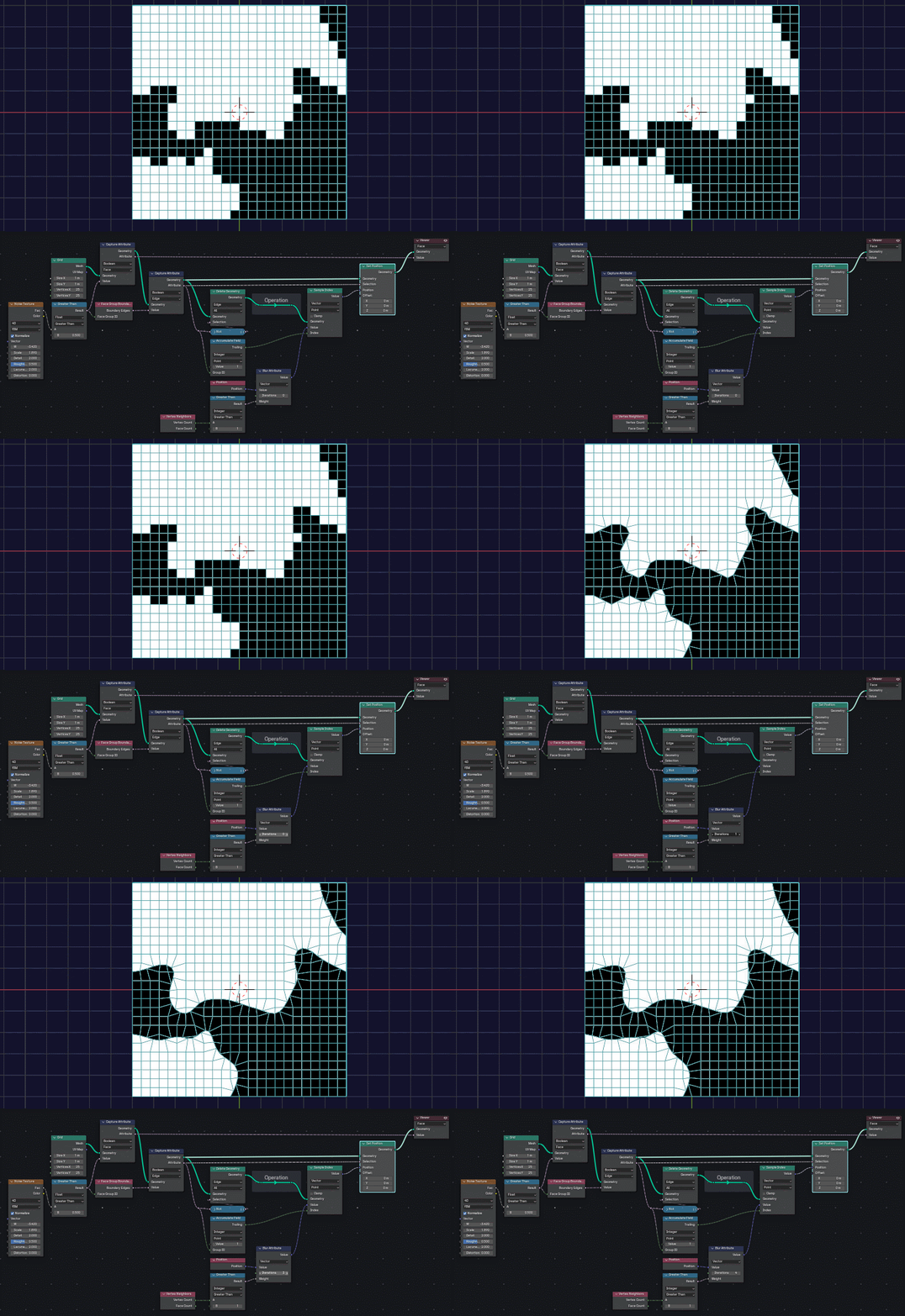
enter image description here enter image description here Here I’m altering the ‘Position’ directly and not the geometry itself because I don’t need to [but it is necessary to use the separate geometry trick for it to smooth only between the boarder vertices].


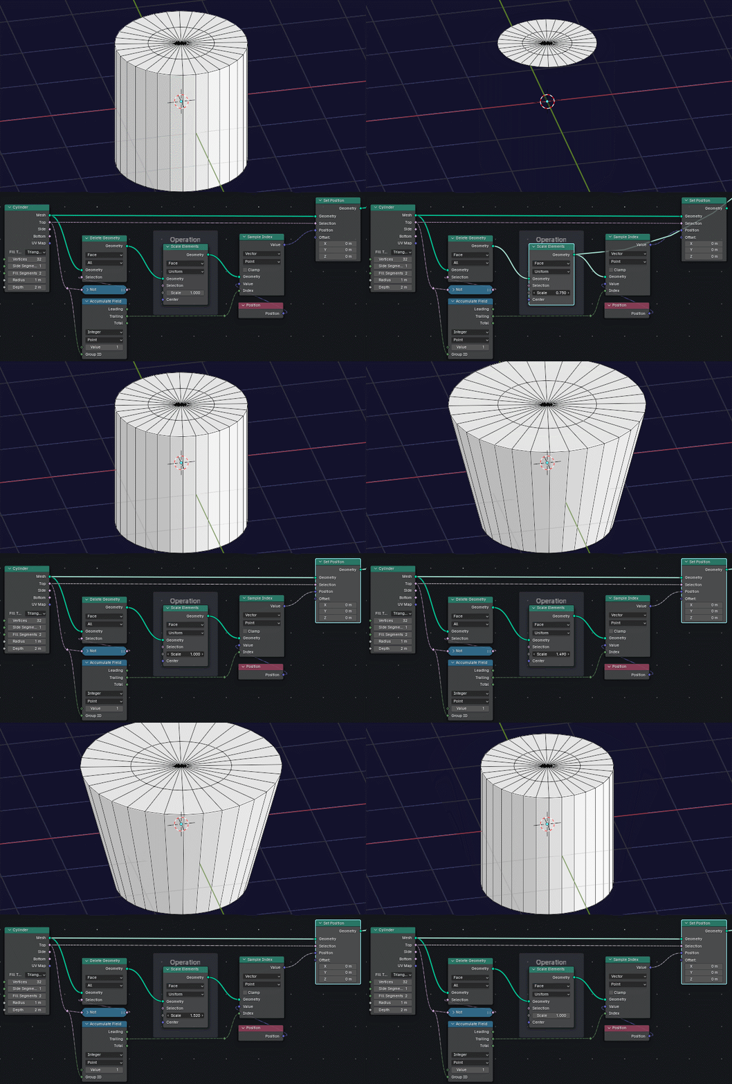
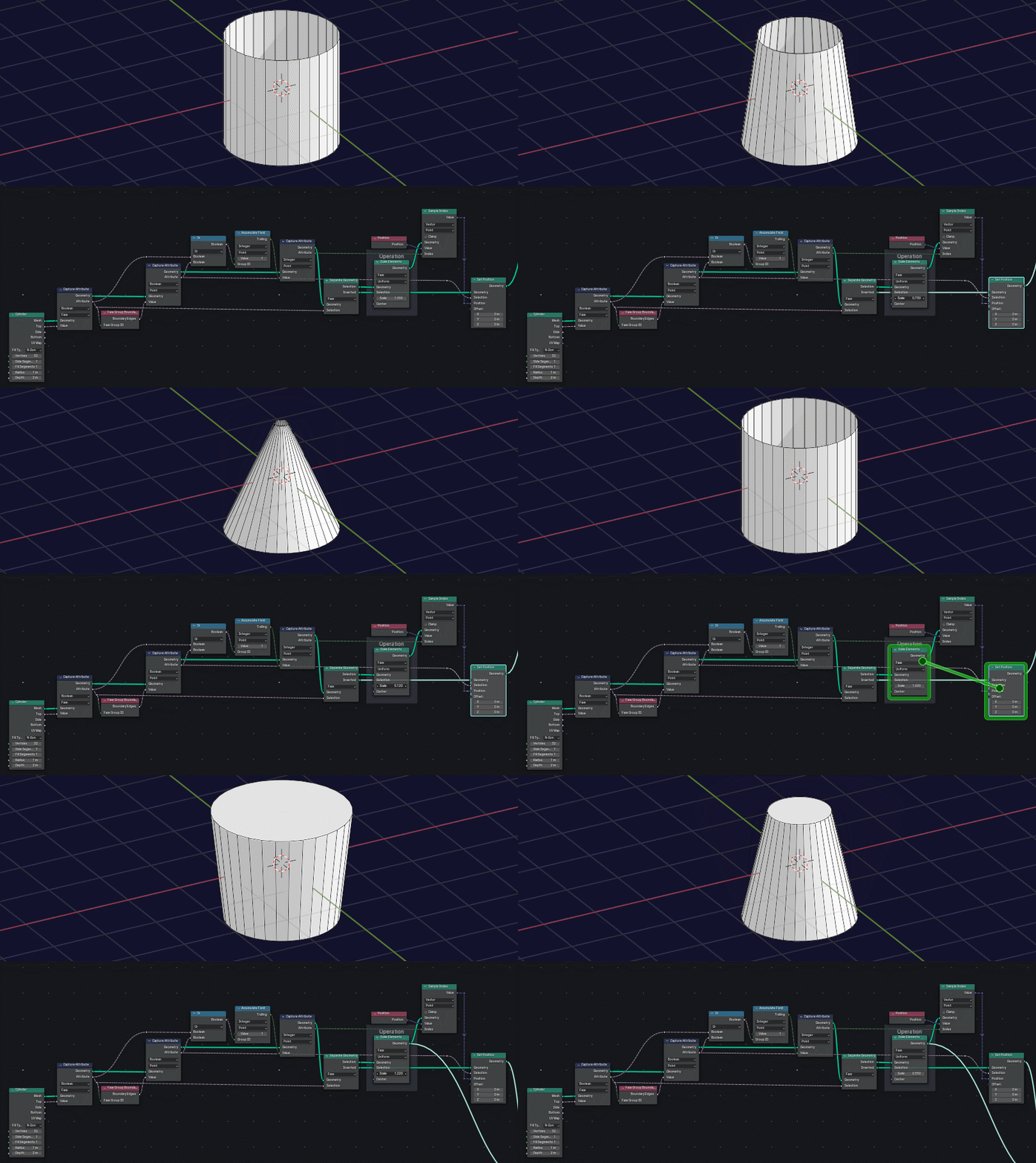
Btw if you wanted to see it on your given example:
enter image description here

enter image description here

(just be be clear; this will work the same way if you just do this .)
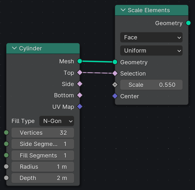
$\endgroup$
4
  • $\begingroup$ thanks for the detailed explanation , I tried the node with cylinder mesh, but it's not working, $\endgroup$ Commented Dec 21, 2023 at 22:41
  • 1
    $\begingroup$ @Pooyaheydari please send a picture. also make sure the everything is the same; if one of the inputs or outputs are wrong it could not work $\endgroup$
    – shmuel
    Commented Dec 23, 2023 at 23:25
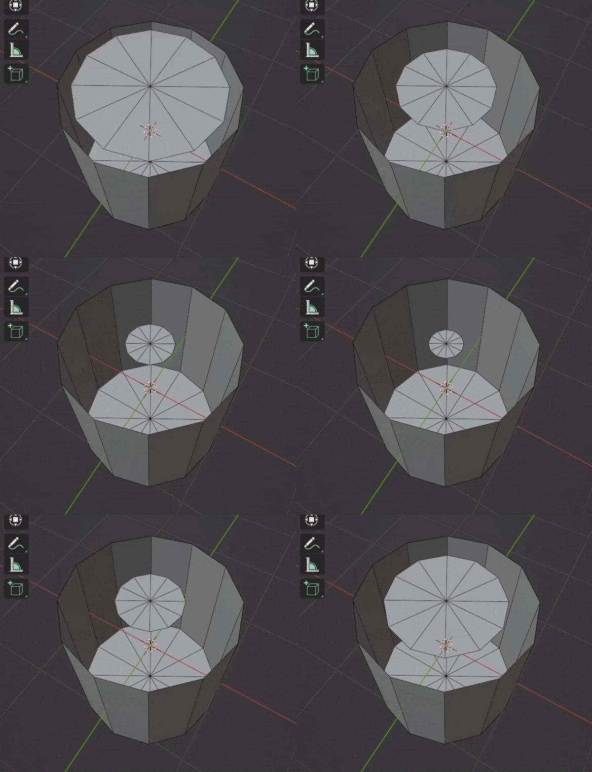
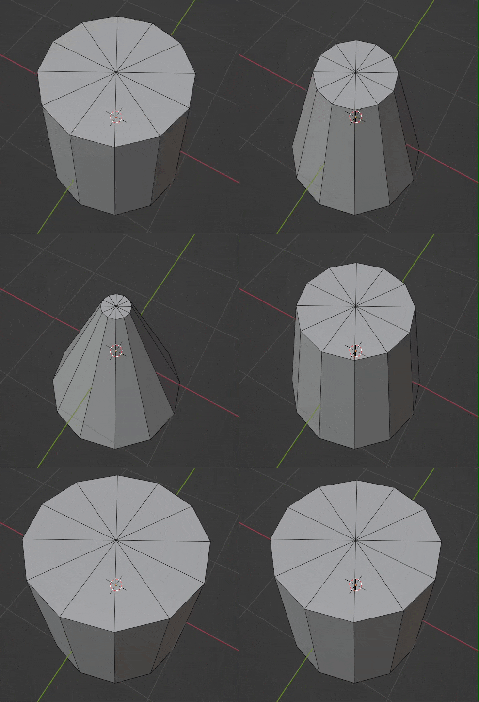
  • $\begingroup$ I just got gifcam so i went a bit crazy 🤪😉 $\endgroup$
    – shmuel
    Commented Dec 24, 2023 at 0:29
  • $\begingroup$ Thank u, now it works fine 😍 $\endgroup$ Commented Dec 26, 2023 at 20:29

You must log in to answer this question.

Not the answer you're looking for? Browse other questions tagged .