4
$\begingroup$

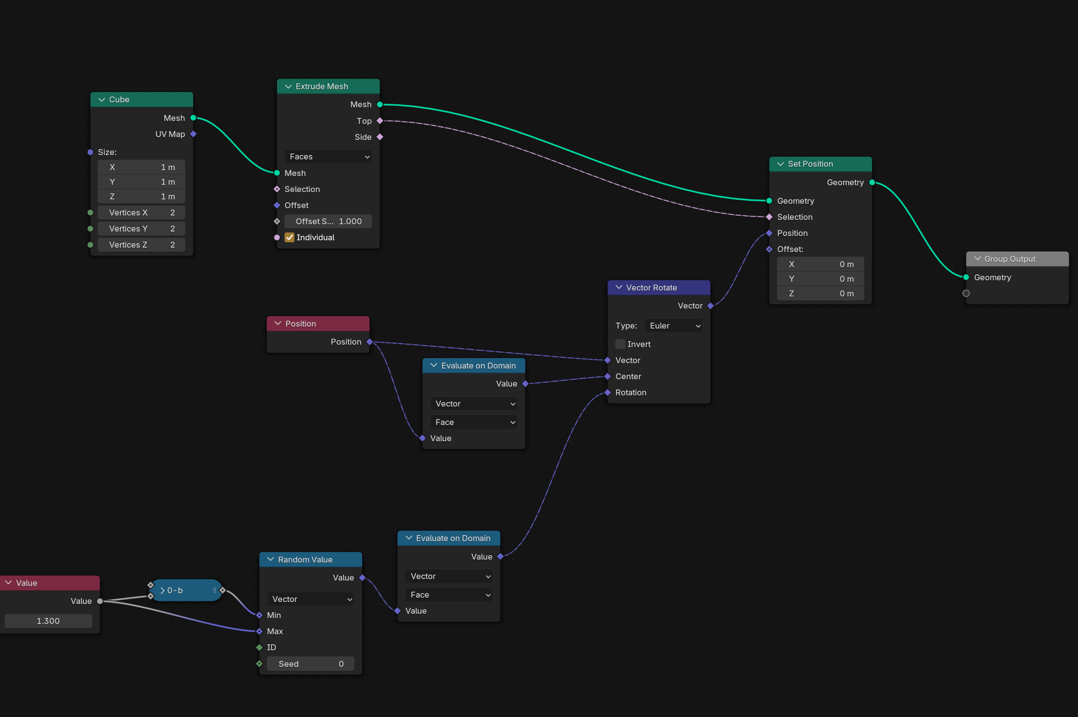
I want to extrude some faces, then rotate the 'top' faces from the extrusion around their centers a random amount. So far I have a Set Position node selecting the top faces from the Extrude node. I use Vector Rotate to get the rotation, and can set the center using a Position node through calculate on domain set to face.

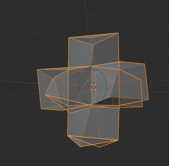
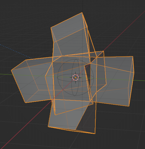
The only problem is that the random number is calculated independently for each vertex, so that the faces become non-planar.

I tried using Evaluate on Domain for the random number, but it doesn't seem to work.

Node tree to rotate faces

Extruded cube that is all wonky

$\endgroup$

4 Answers 4

4
$\begingroup$

Since a vertex belongs to more than one face, your evaluate on face domain is actually interpolating between top and side faces, creating different results.


New solution without "Repeat Zone"

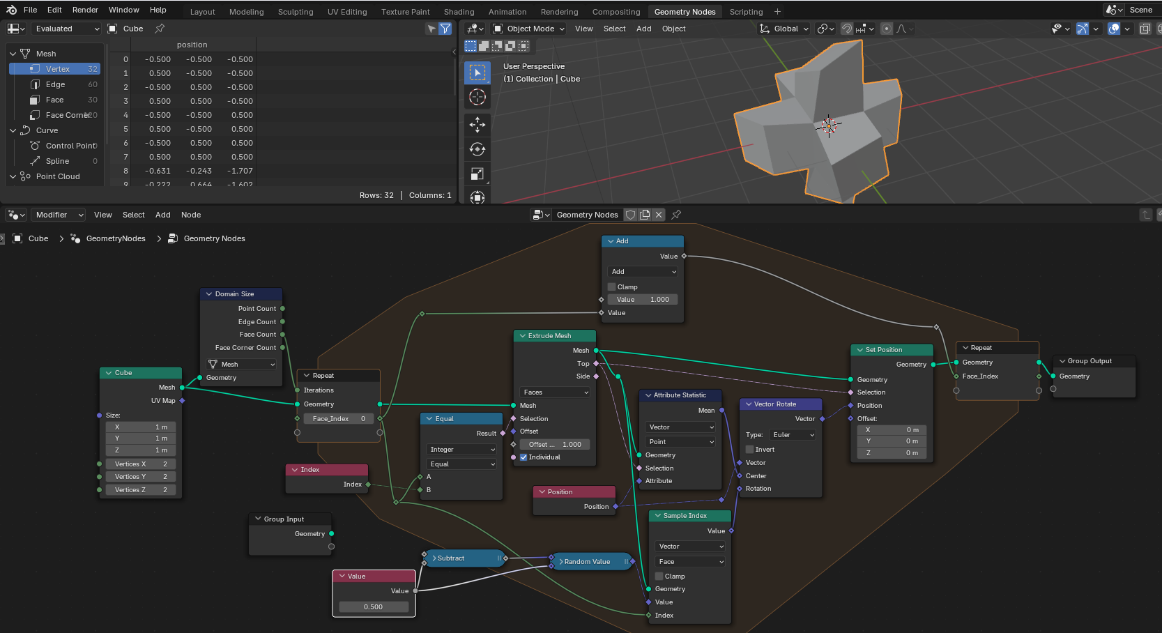
Since repeat zone is very costly, it's better to use just. But to avoid interpolation between top and side faces, we use "face of corner" to select exactly from which face we want to take the position and rotation
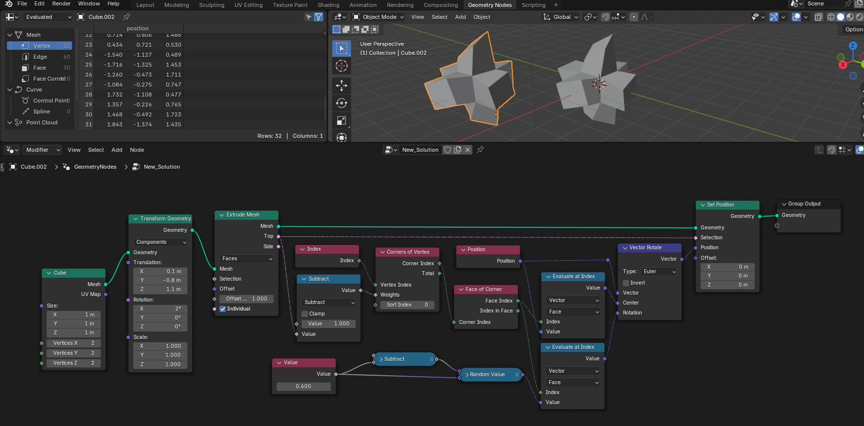
enter image description here

Explanation:

  • We are setting positions for vertices (so every value is evaluated per vertice)
  • If we change the evaluation domain to faces, since we're still evaluating vertices, the results for each vertice will be an interpolation between all faces one vertice is connected to
  • So we use "evaluate at index" with one "face index" to evaluate for one specific face instead of interpolating
  • This face should be the "top" face, and the node that does this selection is "Corners of vertex"
    • Each vertice has a number of corners (= number of faces)
    • This lists all corners, sorts them based on "ascending weights", picks the one with index=0 (the one with the lowest weight)
    • We just need to pass "weights" in a way that the "top face" has the lowest weight
    • The "Top" selection from the extrude node has value = 1 for top and 0 for the other faces. We invert this with the "subtract" so the top has value 0 and the others have value 1 and connect it to the weights

Old solution

Using "repeat zone" is never a great solution, but I think in this case it's the way to go.

Here, we loop each original face and extrude them individually. This way we can take a mean of the vertices and evaluate things on a single face. (This would also allow you to separate the original face and take its center if you want the "arms" to be rotated together with the top faces)

(If you're on Blender 4.3, you can use a "Foreach element" instead of a repeat zone, and a few nodes could be discarded)
enter image description here


File with both solutions

$\endgroup$
10
  • $\begingroup$ I don't really agree for the Repeat Zone, especially if it loops on the vertices and if it can be done simpler as stib's solution. Also performance wise, I'm guessing your solution would be more costly than stib's. I even more discourage to use For Each, about which devs have already warned about the cost and that it should be avoided if attributes can do the job : developer.blender.org/docs/release_notes/4.3/geometry_nodes/… $\endgroup$
    – Lutzi
    Commented Nov 6 at 0:43
  • 1
    $\begingroup$ @Lutzi, that's why I started with "using repeat zone is never a great solution" (performance-wise, my answer is terrible). But, if you look closely at the other solution, it's not exact. The center of rotation is not at the center of the top face (due to interpolation between top and side faces), and the random value is being attenuated by the interpolation as well. It may be more than enough for the OP, but it's still not exact. $\endgroup$ Commented Nov 6 at 0:45
  • $\begingroup$ I also disagree, repeat zone is an amazing tool. In this case it's doing something attributes can achieve and cost way more resources. So, I discourage anyone reading to use loop nodes for this case, especially for heavier geometry. $\endgroup$
    – Lutzi
    Commented Nov 6 at 0:48
  • $\begingroup$ Well... I just confirmed by testing: the other solution is not exact. The center of rotation is not at the center of the top faces. The result is "different" from what was asked. The faces are planar, though. To achieve the proper results with attributes, one would need to transfer the top attributes to the side attributes (including not only rotation, but also position) $\endgroup$ Commented Nov 6 at 0:56
  • $\begingroup$ Sorry I didn't get the issue at first. I see it now, for now I agree that repeat zone appears to be the better way. I'll try to find an attribute-only solution which would be awesome. $\endgroup$
    – Lutzi
    Commented Nov 6 at 1:09
5
$\begingroup$

Math-free field-only solution

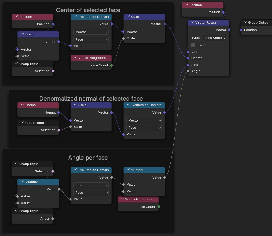
Here would be my way of doing it. It uses fields, which should be light on resources. I wouldn't recommend using Repeat Zone (or upcoming For Each) especially for heavier geometries. It would cost more resources.

We can capture the face position and normal on the face domain, then use these to rotate the position of the vertex.

We have to compute the position after extrusion. Extrusion being achieved along face normal, we scale the normal vector by the same amount as the extrusion and we get the position faces will have.

The issue that Daniel Möller has pointed out is here solved by capturing the position and rotations before extrusion, and thus avoiding interpolation issues. Basically the whole extruded region knows to which faces it should belong. It should work for any mesh.

Here are the nodes and an animation. Credits to Markus von Broady for condensing my nodes and find the minimal setup.

Node tree to rotate faces

Animation in action

$\endgroup$
8
  • $\begingroup$ your normal works, but not your face position, due to interpolation maths mentioned by Daniel Möller here. You need to vector math: scale by the number of face neighbors of the evaluated vertex. To see the problem, try using "transform geometry" before your setup to move the cube away from origin. $\endgroup$ Commented Nov 6 at 0:55
  • $\begingroup$ Aaaah I just clicked, indeed my solution is wrong with a Suzanne head. I'll try work on it. $\endgroup$
    – Lutzi
    Commented Nov 6 at 1:03
  • $\begingroup$ @MarkusvonBroady I also updated my solution, which avoids doing any math. I think it's the simplest we got for now ? Simplest and which works I hope. $\endgroup$
    – Lutzi
    Commented Nov 6 at 1:50
  • 2
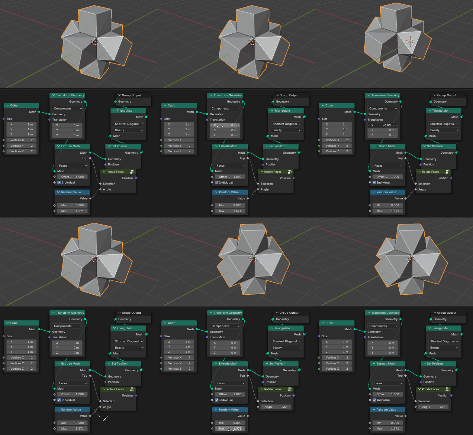
    $\begingroup$ Great! You're capturing needed stuff before extrusion, so that all extruded geometry has a copy, and therefore the average takes the same values, so interpolation gives the original value. Here's this setup simplified to just 10 nodes (+ transform for testing + triangulate for better triangulation) i.imgur.com/ChBC7IL.png $\endgroup$ Commented Nov 6 at 9:25
  • 1
    $\begingroup$ Oh nice ! I'm updating, thanks for the input ! $\endgroup$
    – Lutzi
    Commented Nov 6 at 11:23
4
$\begingroup$

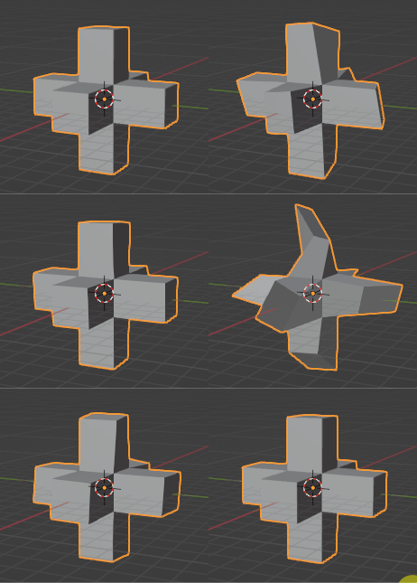
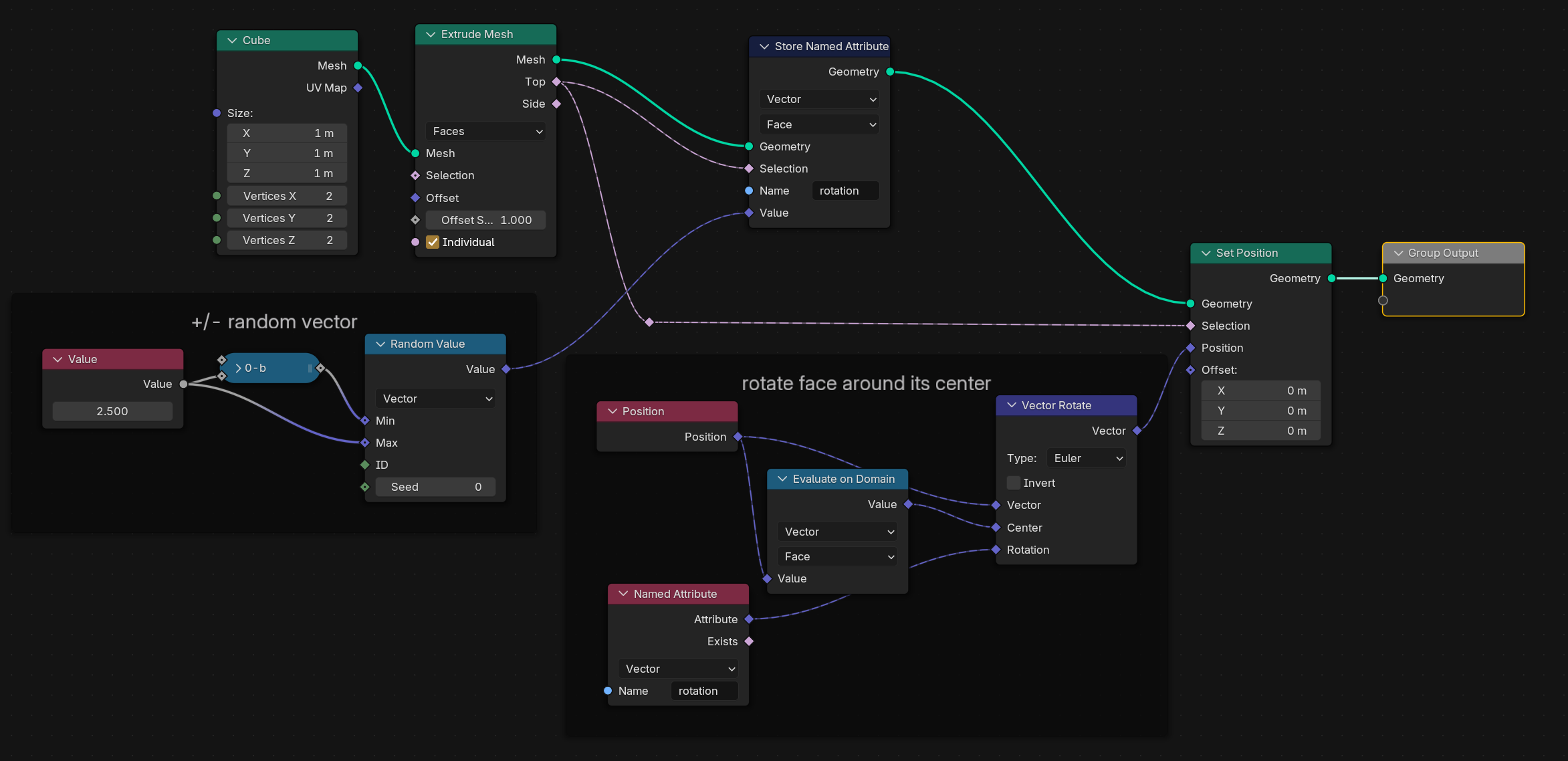
The trick is to store a random rotation as a named attribute on each face. Seems a bit kludgy, but because it stores a single rotation vector for each face it works.

node tree

planar rotated extrusions

$\endgroup$
1
  • 2
    $\begingroup$ Although your answer is way cleaner than mine, I believe the named attribute is also being interpolated (as in the original question), and that's why you need a greater value (2.5, compared to 1.3) to achieve small rotations. Since all neighbor faces have zero rotation, the interpolation ends up equal in all vertices. I guess the desired rotation value should be multiplied by 3 (always two side faces and one top face connected to the vertex) $\endgroup$ Commented Nov 6 at 0:15
3
$\begingroup$

Daniel Möller is right in the comment under stib's answer:

[...]the named attribute is also being interpolated (as in the original question), and that's why you need a greater value (2.5, compared to 1.3) to achieve small rotations. Since all neighbor faces have zero rotation, the interpolation ends up equal in all vertices. I guess the desired rotation value should be multiplied by 3 (always two side faces and one top face connected to the vertex)

The interpolation averages all surrounding faces:

$$x = {x_1 + x_2 + x_3 + ... + x_n \over n} $$

You can multiply unselected values by zero (and conveniently boolean translates to one or zero):

$$x = {x_1×0 + x_2×1 + x_3×0 + ... \over n} = {x_2\over n} $$

So to get the actual selected value, multiply it by $n$.

There's so many answers here that I decided to add additional quirk, making it a pure field:

Imgur mirror (SE image hosting has problems)

Now you can use it like so:

Imgur mirror

$\endgroup$
2
  • $\begingroup$ Whoa!! Great. Are pure fields faster than named attributes? $\endgroup$ Commented Nov 6 at 1:32
  • 3
    $\begingroup$ @DanielMöller I don't think the difference (whatever's faster) is significant, it's more important that you won't get a name collision. However, by "pure" I just meant that there's no geometry socket in the group, so you can use it to calculate positions without actually modifying them, perhaps useful to chain operations efficiently, but I don't know if that will be useful to anyone. $\endgroup$ Commented Nov 6 at 1:35

You must log in to answer this question.

Not the answer you're looking for? Browse other questions tagged .