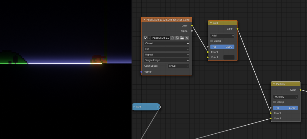
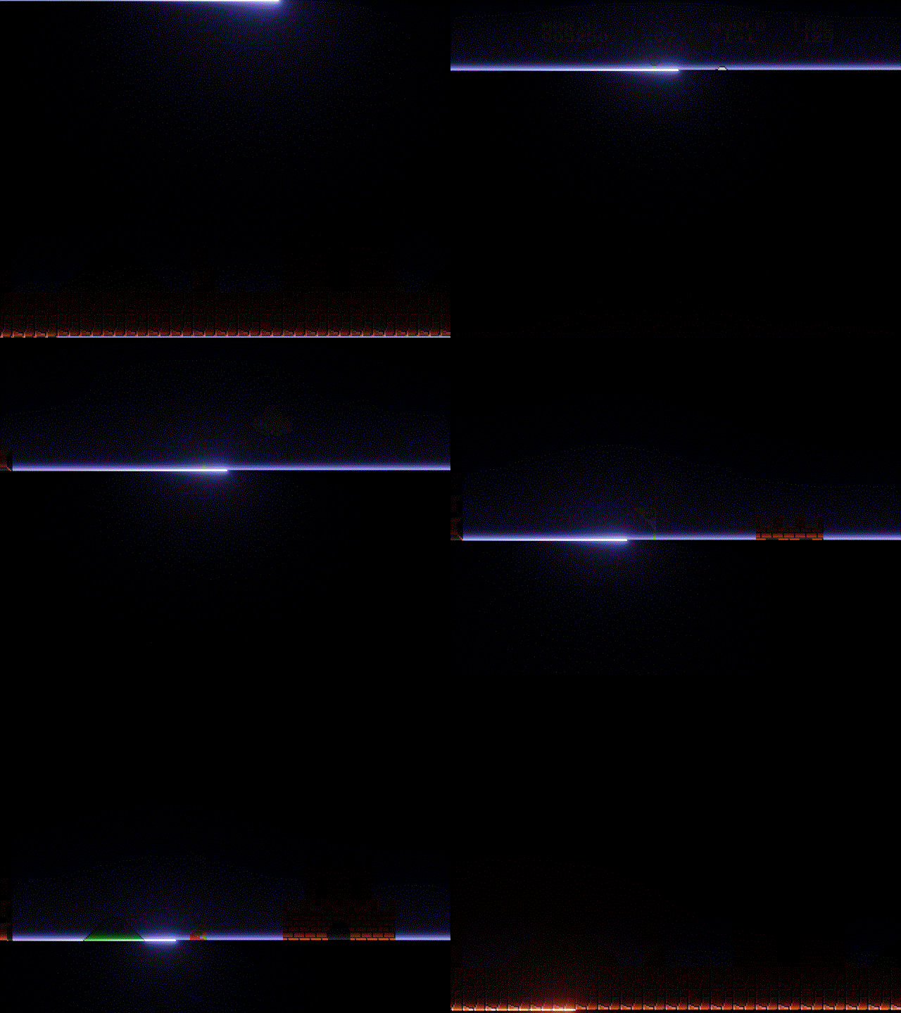
I want to create the CRT refreshing effect as shown in the GIF: 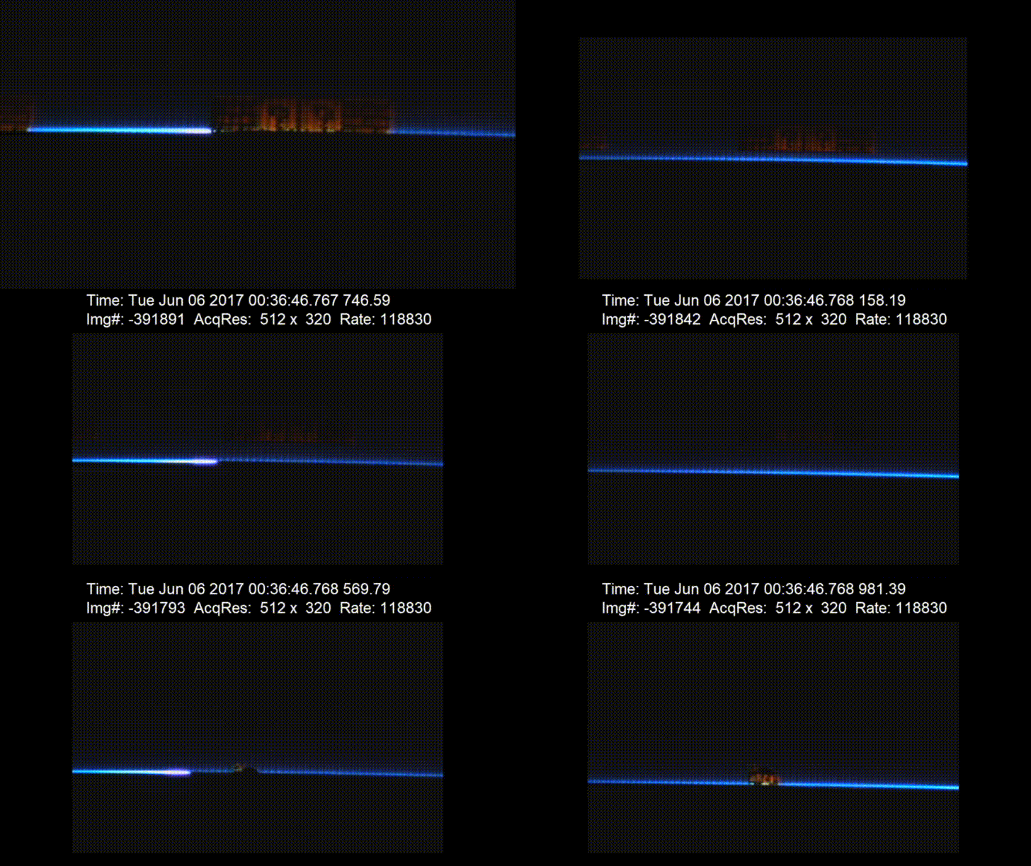
Now how do I do that?
This can be done by quantizing the x and y generated coordinates and combining them to get a unique value in $[0, 1)$ for each pixel. Then it's just a matter of creating a falloff for the scan lines.
The y coordinates have been inverted by the subtract node so that the scan lines will start at the top.
Here I have created a plane with a $4:3$ aspect ratio like a CRT would have, and for the material, I have assigned a material that takes the floor of the $x$ multiplied by horizontal resolution (640). This gives an index from 0 to 639 for each column of pixels.
The same can be done to the $y$ except multiplying by the vertical resolution (480) giving an index between 0 and 479.
By multiplying the row indices by the horizontal resolution, you can get an offset of 640 for each row that can be added to the column indices to get a unique index for every pixel.
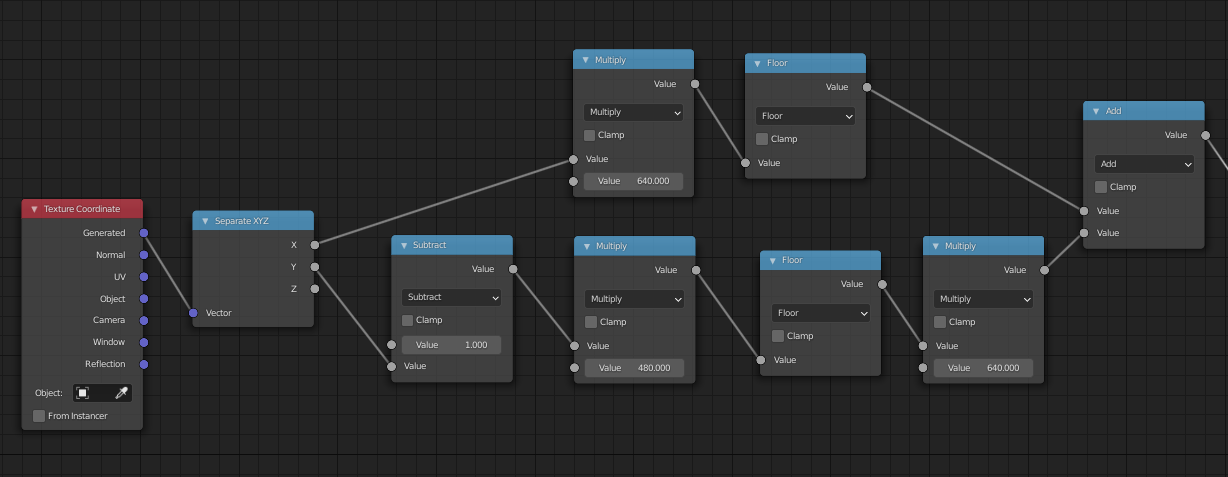
I like to work in the zero to one range, so I will divide the pixel indices by the total number of pixels $640 \times 480 = 307,200$. This will result in what looks like a smooth top to bottom gradient, but it is actually a quantized left-to-right, top-to-bottom ordering of pixels each with a specific value in $[0, 1)$.
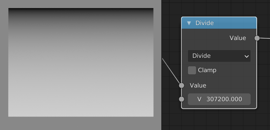
These values are essentially the domain of the yet-to-be-created falloff function.
But before we make the falloff function, let's create an offset that can be used to move the falloff along the scan lines.
To do this I have created a subtract node with the subtrahend being driven by the expression #frame/480/9. This means that in nine frames, the domain will shift by one scan line (480 total scan lines).
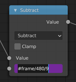
So that the scan lines will repeat once the end is reached, I added a Fraction math node.
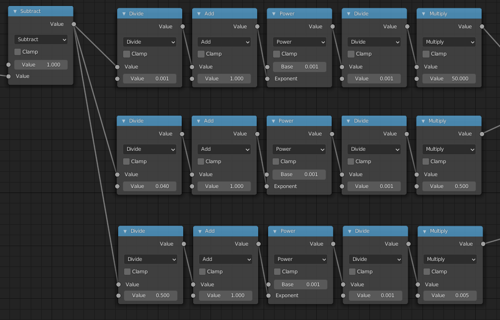
To create the falloff function, I will use three exponential functions: one for the short, initial flash of the electron beam, one for the slightly longer colorful trail, and one for the faint ghosting.
The important values are the divisor of the second node and the factor of the last node. They are the length of the trail and the brightness respectively.
To create the other two functions, just select everything after the subtract node, press ⇧ Shift⎈ CtrlD and move 'em down twice.
Adding these all together with the values I used gives this.
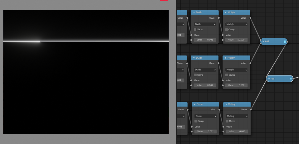
To make it actually draw something, you can simply multiply the above output by an image texture. (I've added a dark gray to the image so that this CRT isn't an OLED.)
