6
$\begingroup$

I'm trying to connect a set of points to their nearest neighbour.

Steps I took:

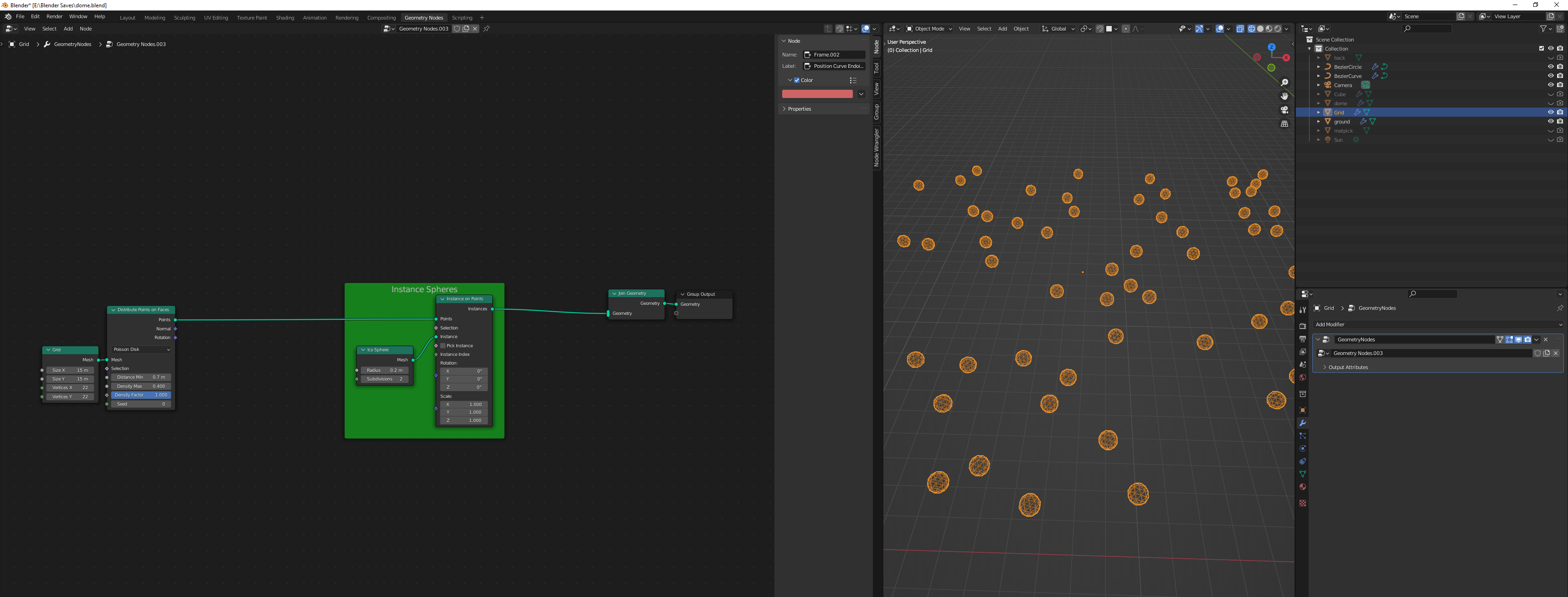
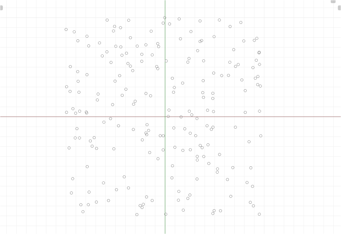
Instance some points on a grid enter image description here

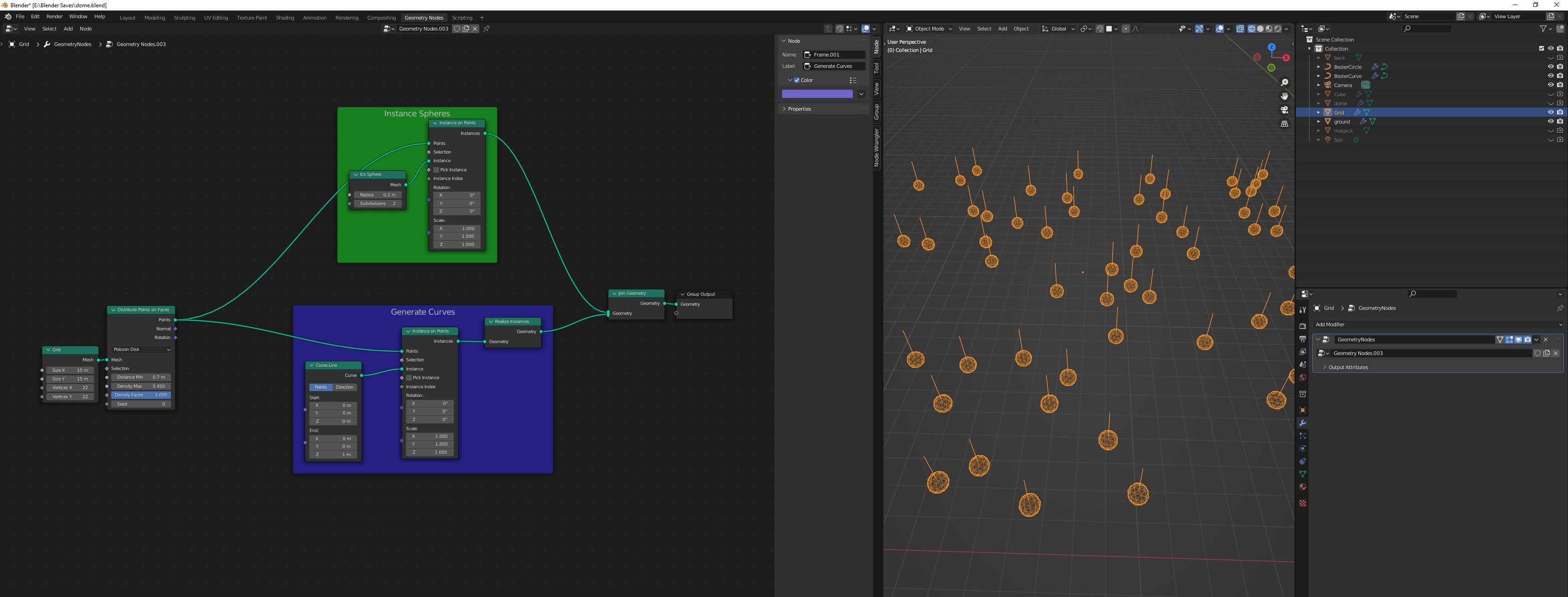
Add a curve at each point and realize so I can affect them individually enter image description here

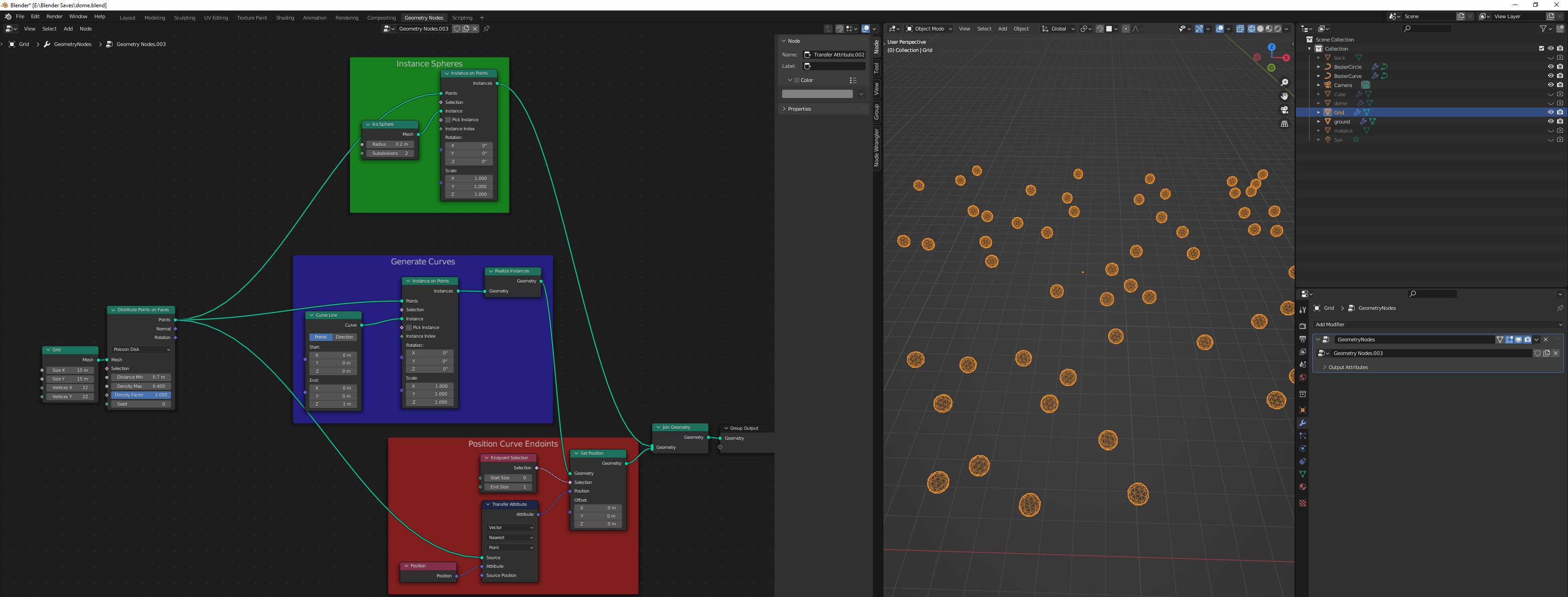
Move the endpoint of each curve enter image description here

I think I'm misunderstanding what Transfer Attribute is doing. I thought this is saying:

Take the points on my grid, calculate the closest point to each point, pass the field of those positions as an attribute. The Set Position node is then taking that field of positions and using it to move the endpoints of each curve.

Clearly, I'm missing something though!

$\endgroup$
2
  • $\begingroup$ For the transfer attribute, the closest point is the point itself... $\endgroup$
    – Crantisz
    Commented Feb 8, 2022 at 12:31
  • $\begingroup$ Ooooooo.... that makes sense. Still not sure how I do 'nearest but not this one' but at least I understand why that wasn't working! $\endgroup$
    – Ben
    Commented Feb 8, 2022 at 13:08

3 Answers 3

7
$\begingroup$

Blender 3.6+

This answer is technically the same solution as shown here:
How could I get the distance of a point to its nearest point?

With Blender version 3.6 a new node is available that makes this task a lot easier: Index of Nearest.

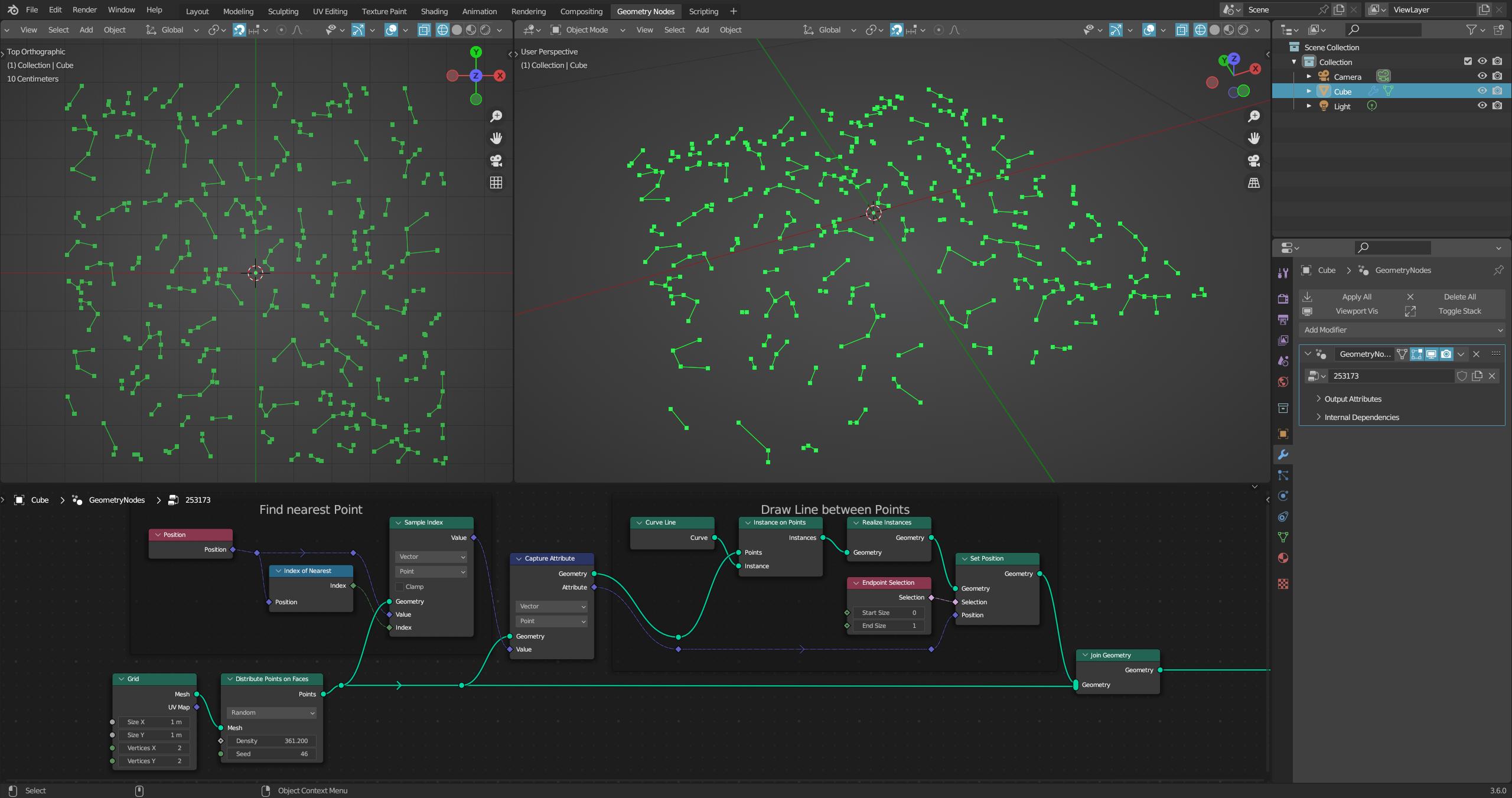
The node Index of Nearest simply returns the index of the nearest point, which makes it just as easy to query its position with Sample Index. Then you just need to instantiate lines, and move their endpoints to the position of the nearest point:

enter image description here


(Blender 3.6+)

Blender 3.1+

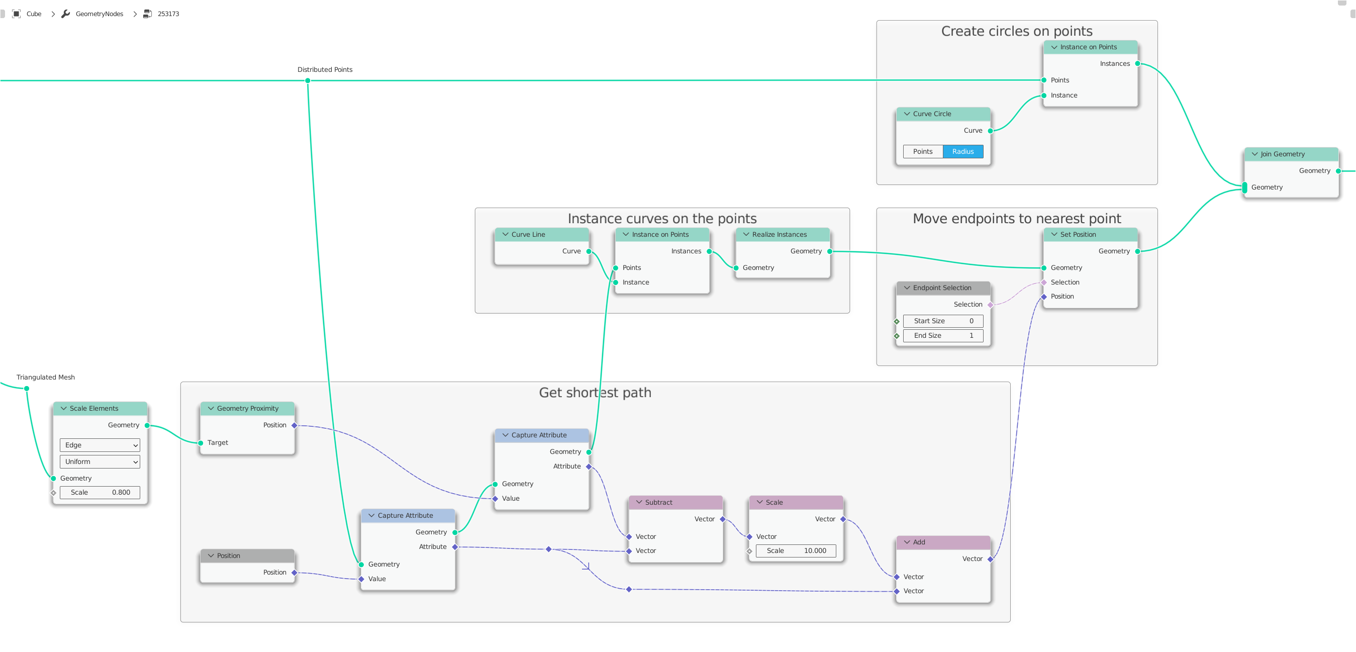
The desired result can be achieved with the technique The shortest edge trick.

All you have to do is to convert your randomly generated points into a triangulated mesh and apply the following principle:

Selectively join points using geometry nodes - Nodes

If you use the node Distribute Points on Faces, you can achieve the triangulated mesh you need in this way, for example:

Selectively join points using geometry nodes - Triangulated Mesh

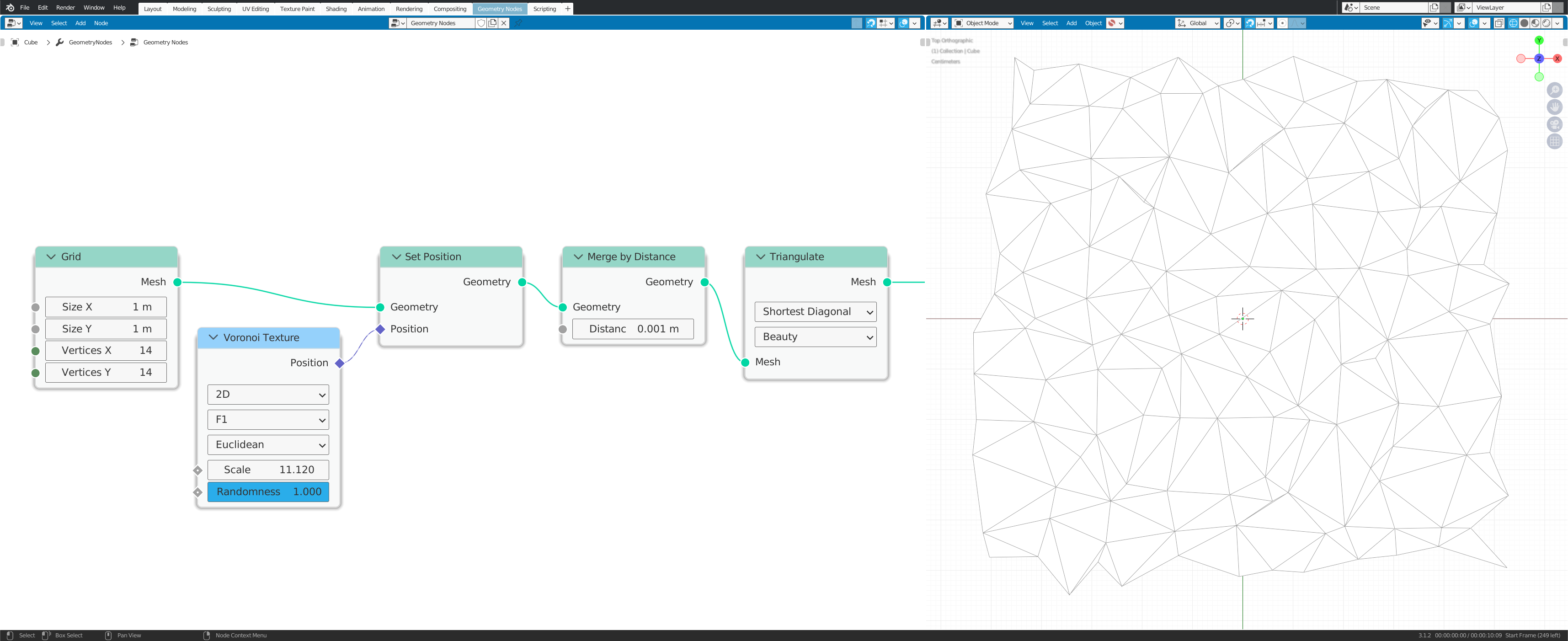
But if you use the node Distribute Points on Faces to create only the points, there is also a convenient alternative: The node Voronoi Texture.

If you only need randomly distributed points that you want to connect, it is sometimes easier to create a triangulated mesh directly instead of turning points into a triangulated mesh.

Here's an example of how that can work:

Selectively join points using geometry nodes - Voronoi Texture

Once such a mesh is available, and this is actually the more complicated part in this case, it is easy to find out the shortest distance.

The procedure in this case would be as follows:

  1. Create your points on a grid

    Selectively join points using geometry nodes - Screen 1

  2. Create the triangulated mesh

    Selectively join points using geometry nodes - Screen 2

  3. Shorten the edges by a certain factor

    Selectively join points using geometry nodes - Screen 3

  4. Find the nearest edge and instantiate your lines there.

    Selectively join points using geometry nodes - Screen 4

Here is the blend file:


(Blender 3.1+)

$\endgroup$
7
  • $\begingroup$ Now, that I see it, I remember again. Should have remembered earlier. ;-) I really like this solution. $\endgroup$ Commented May 2, 2022 at 16:53
  • $\begingroup$ @AndréZmuda Oh yes, this technique is funny, thanks, but I actually already liked your answer too ...why did you delete this one? $\endgroup$
    – quellenform
    Commented May 2, 2022 at 18:54
  • $\begingroup$ it was much too complicated. Both of the solutions in the thread, that you refered to, are much better. $\endgroup$ Commented May 2, 2022 at 19:45
  • 1
    $\begingroup$ @AndréZmuda I would not say that one or the other method is better or worse, because both answer the question asked well. They are definitely very different, and that's exactly why I wouldn't have deleted your answer. Diversity is important! $\endgroup$
    – quellenform
    Commented May 2, 2022 at 22:27
  • 1
    $\begingroup$ Ok, you convinced me. ;-) I undeleted it. $\endgroup$ Commented May 2, 2022 at 22:30
4
$\begingroup$

Even if this one is not as elegant as the one of quellenform, I will explain it as just another way to solve the task.
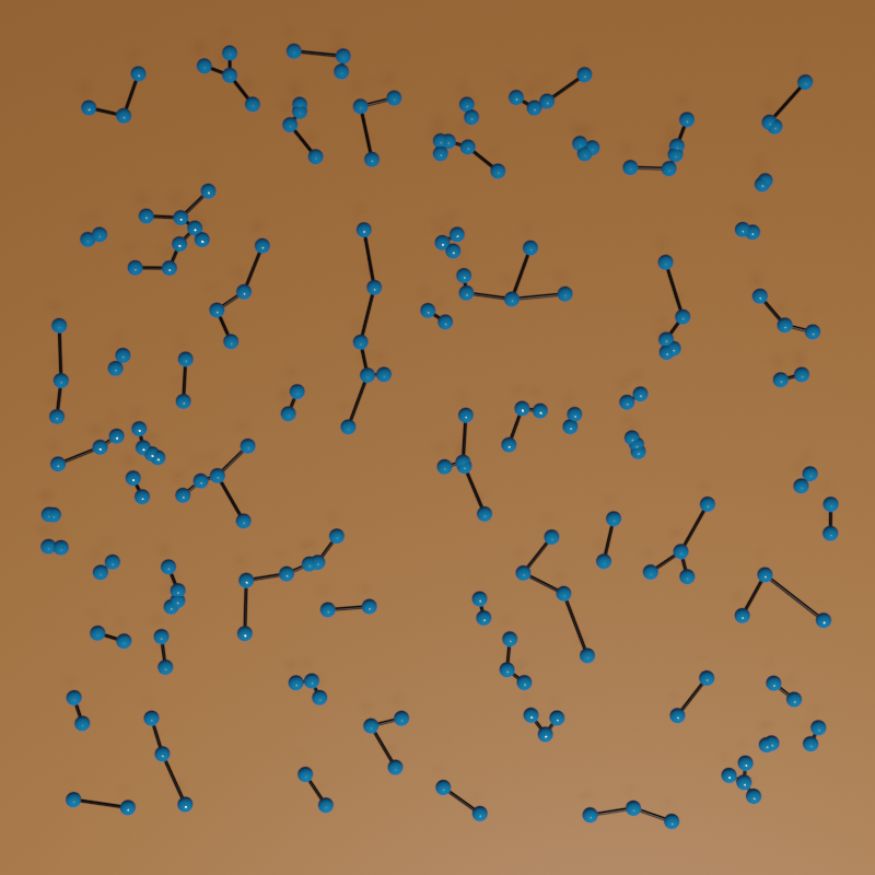
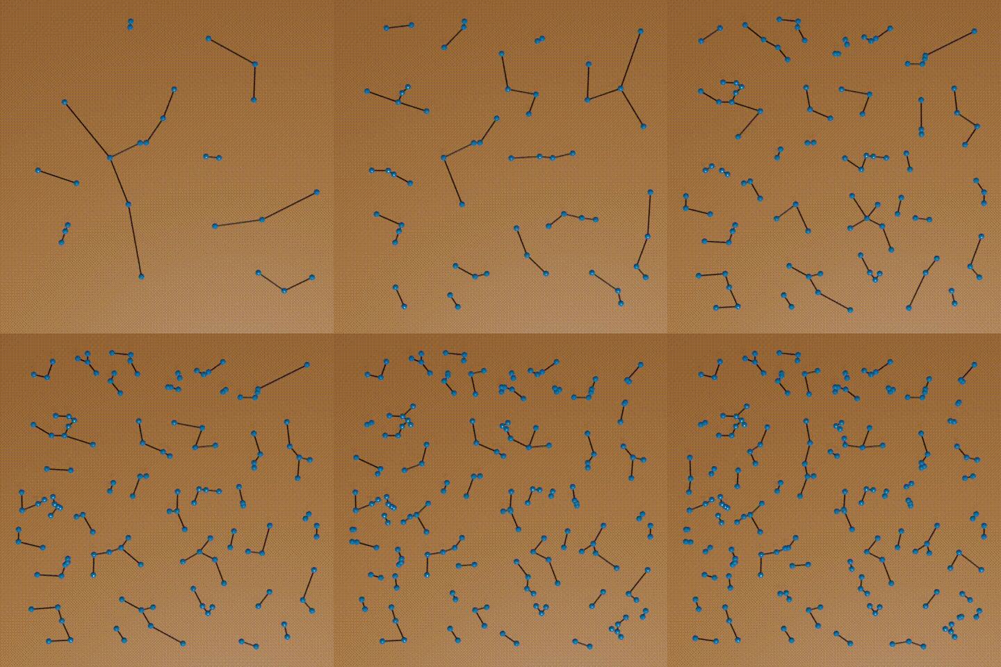
result

result dynamic

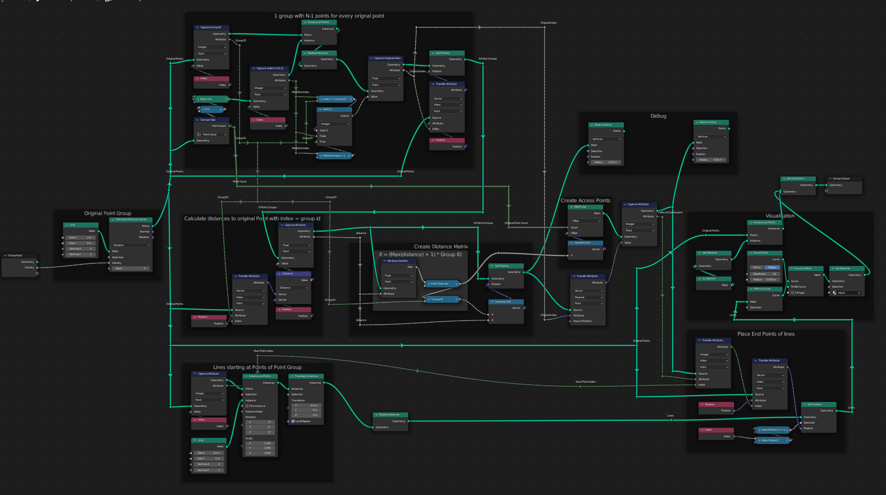
node setup

The Algorithm

First, we create a copy of the point cloud for every point in the cloud. We store the original index at every point in this cloud. Only, this copy does not include the original point itself. Then we take every combination of point and correlating point set, calculate the distance to this point for every point in the set and store this value at the point in the set.

We create another copy of the original point cloud and place every point of this cloud on the x-axis. These points are placed in a distance, that is greater than the maximum of all distances that we computed before. Every of these points represents the index of an original point.

Now, for every of the above created point sets, we place the points of the set in z-direction above the corresponding index point. And we place them in the distance that we computed before (z = distance).
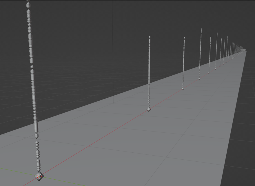
point stacks

Starting at the original points, this allows us to access the index point based on the index of the original point. Using the index point, we can find the nearest point of the generated sets. And using the index, that we stored at this point, we can access the position of the original point. Finally, this allows us, to draw a line from the starting point to this point, which is the closest point in the original set.

Implementing the Algorithm

We start with generating the large N*(N-1) point cloud:
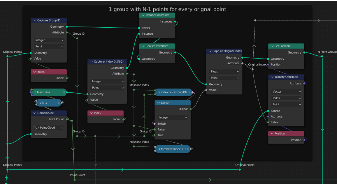
generating the point cloud

First the index of every original point is saved as the Group ID at the point by using a Capture Attribute node. Next a Mesh Line with N-1 points is initialized on every of these points. The original Mesh Line Index is conserved by using a Capture Attribute node again.

As we want to skip a different point in every subset, we use the Mesh Line Index to calculate the “Original Index” for every point. Then we place every point of the Mesh Lines directly on the original points, so that we can use them to calculate distances.

Now that everything is prepared and in place, calculating the distances for every combination of 2 points is easy:
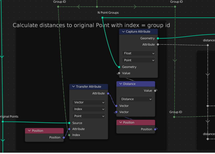
calculating the distances

The distance value is saved at the points of the N*(N-1) points by using a Capture Attribute node.

The distance values allow us, to place all points in the manner that is displayed in the first image up above. These are the nodes, used for doing this:
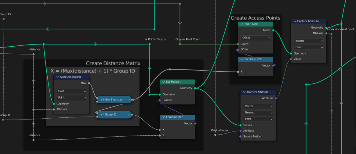
sorting the points

Next, the index of the closest original point is stored at every point in the N*(N-1) points with a Capture Attribute node.

Finally, the lines are created. We start by placing the first point of every line directly on one of the original points:
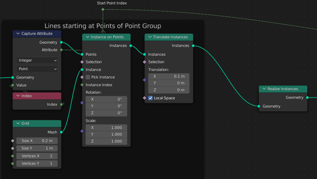
creating the lines

To place the second point of each line, we get the index of the closest point from the point cloud based on the starting point index of each line. We use this index in order to read the position of the original point and place the second point of the current line directly on it.

The only thing left to do is, to merge all points by distance and visualize the result.
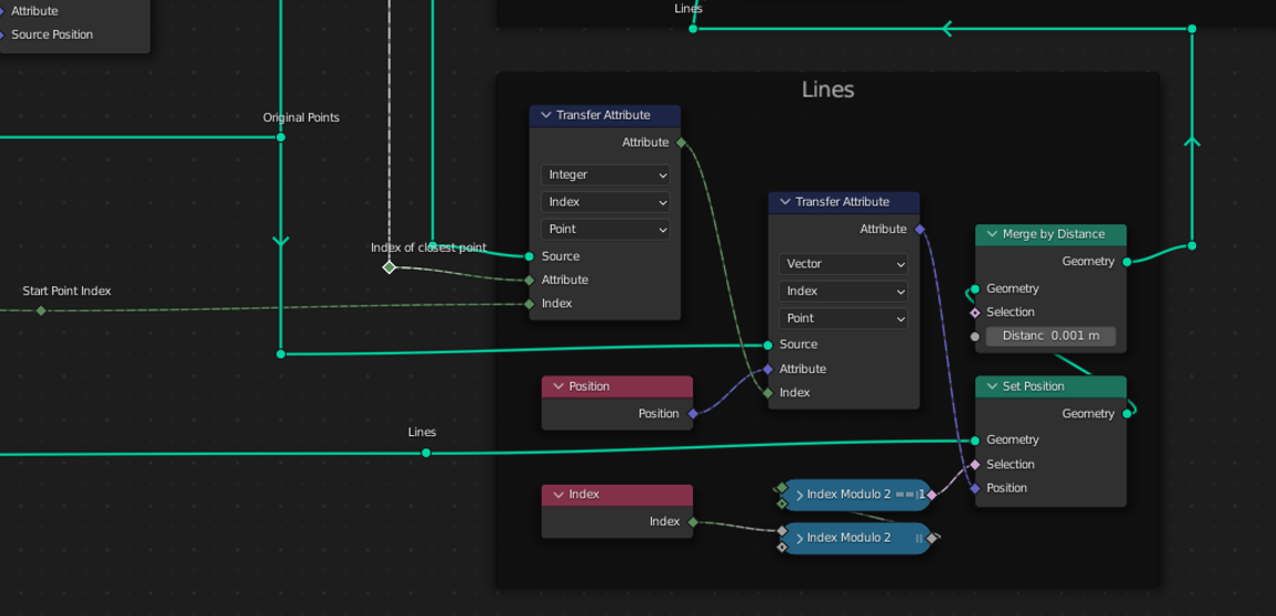
finalizing the lines

$\endgroup$
2
  • $\begingroup$ helloAndre, is there a way to adjust how far the points get connected? like a distance threshold $\endgroup$
    – Urfbs
    Commented Nov 5, 2022 at 15:47
  • $\begingroup$ @Urfbs see my answer $\endgroup$ Commented May 27, 2023 at 21:36
4
$\begingroup$

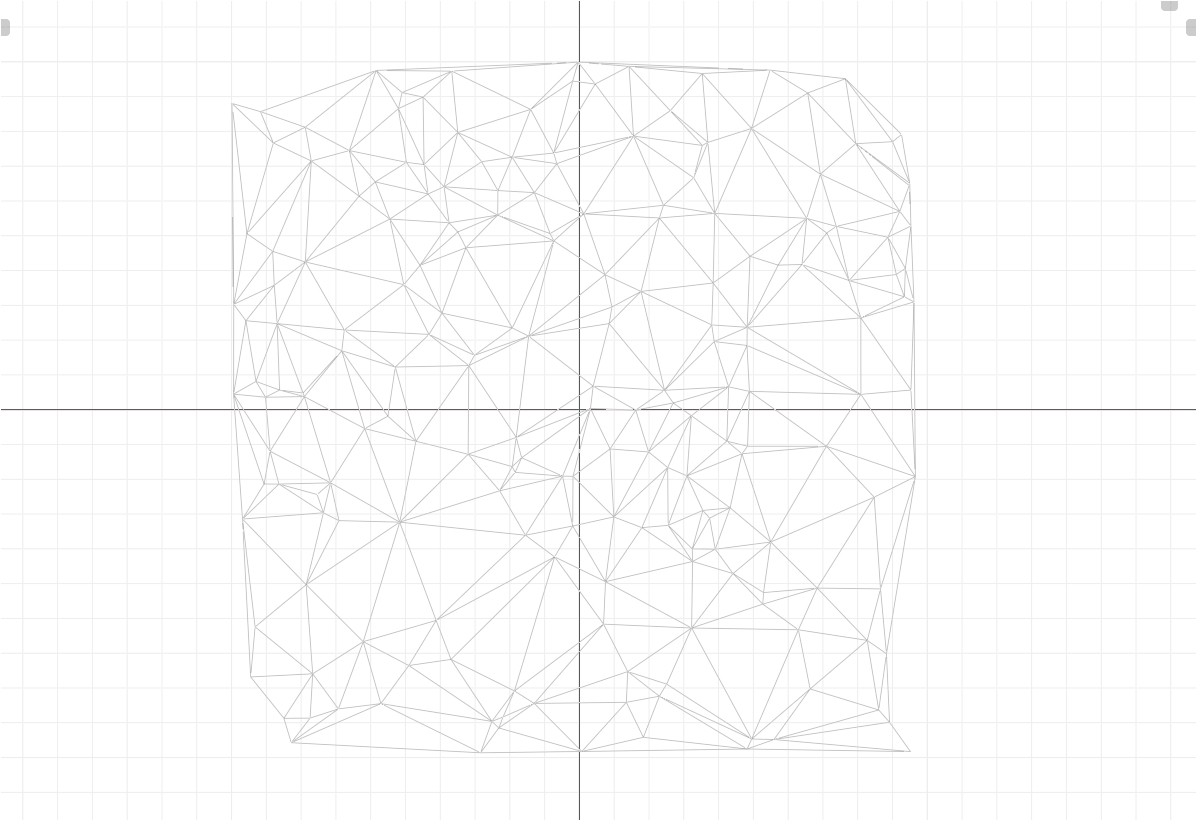
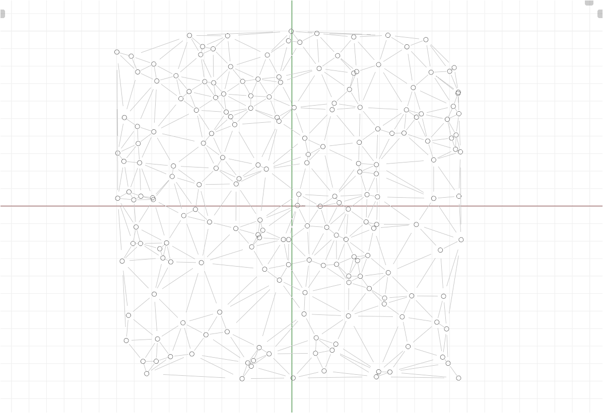
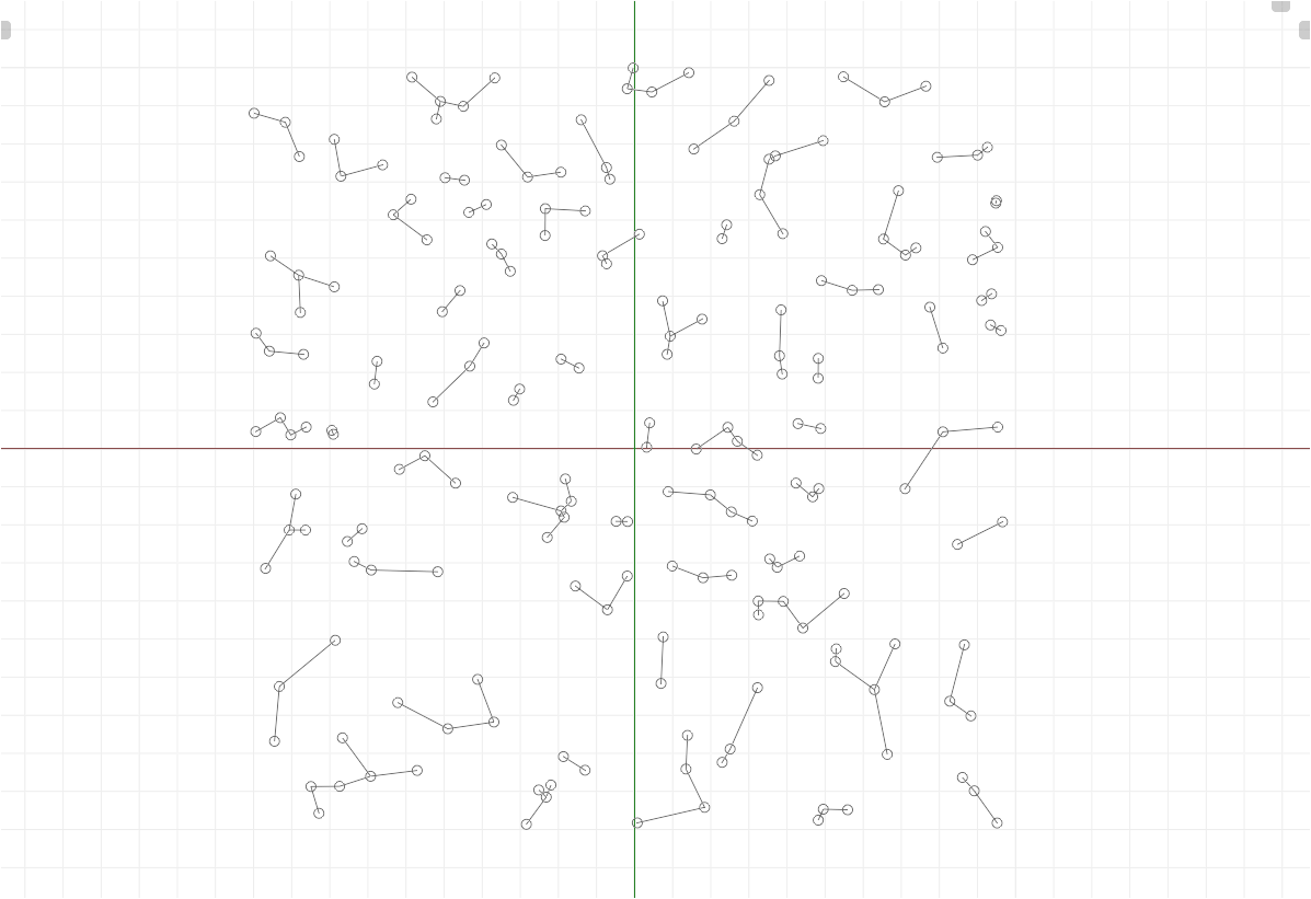
Blender 3.4 introduced Mesh Topology Nodes, which allow efficient sorting. This makes it easier not only to find the nearest point (BTW, there's a special node coming to find nearest element not counting self), but also multiple nearest points.

Part 1: Connect All Points

Connect each point with every other point (also with self, doesn't matter):

Part 2: Find nearest(s)

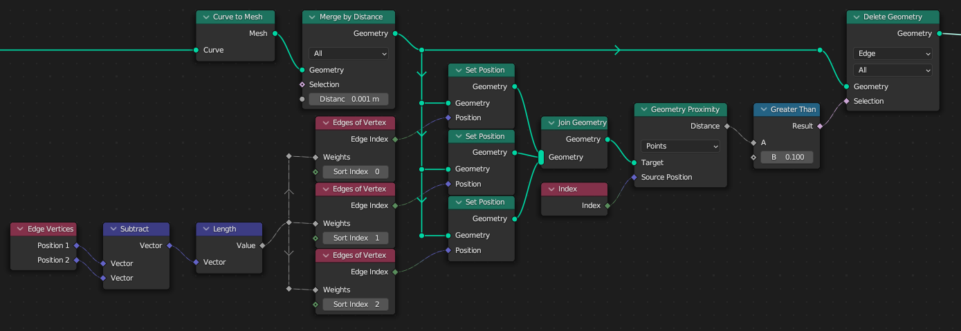
Now merge "doubles" and for each find the shortest connected edge using the new topology node "Edges of Vertex". Because you want to access this information later in the edge domain to delete "unused" edges, create a mapping simply by positioning the points on the XYZ = edge's index, then for each edge you can check if a point was moved to its index as XYZ:

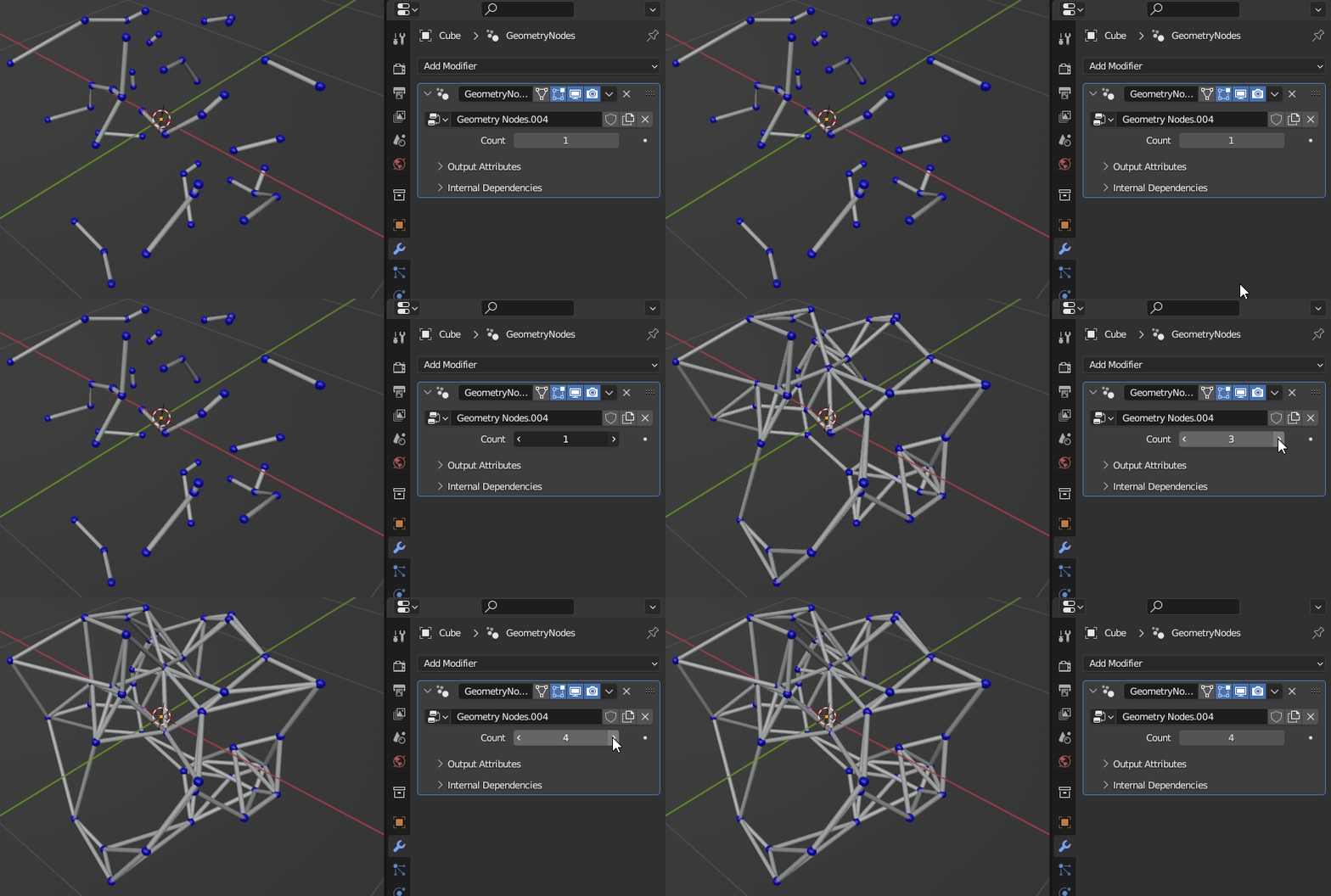
Above I also repeat it for the 2nd and 3rd nearest and it should be clear how to continue adding more nearest. You could make the number of nearest elements dynamic, by repeating the quadratic "Instance on Points" self on self trick in order to produce more points for the "map":

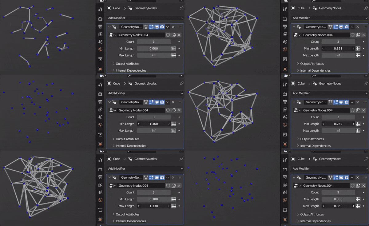
This time I used anonymous capture attributes to show that you can. I also added a check for min/max length because Urfbs asked for it.

Part 3: Display the result

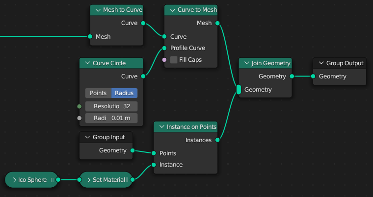
Here's the result as well as the missing part of the node tree to accomplish it - just in case the .blend file is unavailable:

$\endgroup$

You must log in to answer this question.

Not the answer you're looking for? Browse other questions tagged .