deleted 86 characters in body
Source Link
Carlo
  • 24.9k
  • 2
  • 50
  • 93

enter image description here

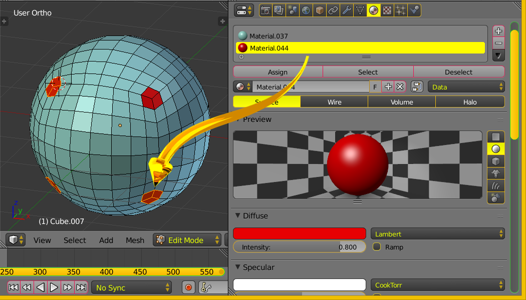
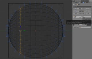
The image above shows a blue mesh with a sphere shape, hereafter the blue sphere. It is symmetric about the 3 axis similar to a cube. Note the red faces have a 3 face corner not a 4 face corner. Not a UV Sphere. The mesh will work symmetrically along x, y, z axis with a cast cuboid modifier.

In the image in your original question concentric rings of the UV Sphere are placed along the z-axis. Speaking about the default situation. So the there is an asymmetry regarding the z-axis. So the [cast] modifier mathematics amplifies this asymmetry. You will get slightly better results if you subdivide your mesh again.

You can edit the blue sphere in [edit] mode and rotate 90 on the y axis. The asymmetry deformation will be rotated as well.

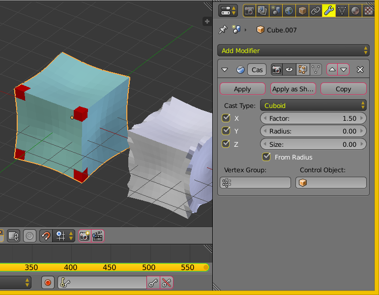
Here is the same blue sphere shaped mesh with a cast modifier. Note again the red faces which form a 3 face corner of a cube.

enter image description here

To create a NON-UV sphere shaped mesh. Create a cube. In [edit] mode loop cut on with 7 or so divisions. Loop Cut on all three axis XYZ. Menu Transform ..... Transform to Sphere.

Yes, start with cube, transform to sphere shape, cast back to cuboid.

Additional Notes Please welcome Carlo


Cast modifier basically projectprojects the object vertices along their normals to the target shape's surface. It is the same thing you would get by using a Shrinkwrap modifier pointing to a scene object.

enter image description here enter image description here

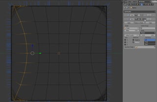
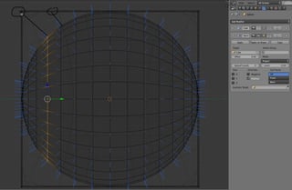
By enabling Vertex normals in Edit mode, you can see on what surface each vertex will be translated to.

enter image description here enter image description here

enter image description here enter image description here

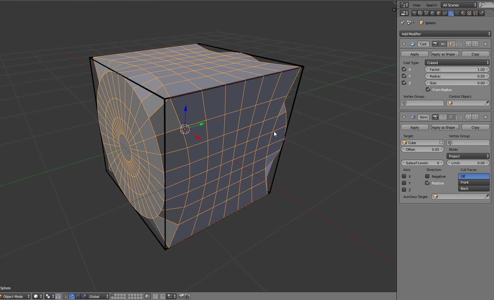
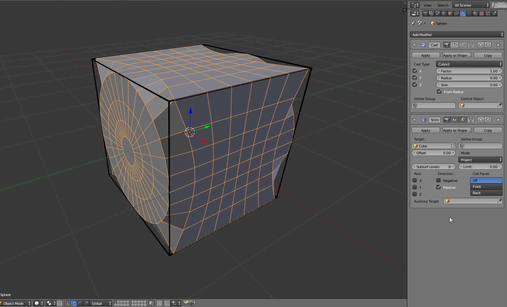
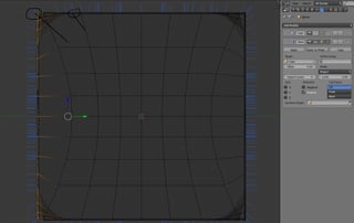
As you can see at some pointThere is no vertex normals suddenly switch faces they are pointing to, resulting intoward the less than desirable shape you gotbox's corner.

enter image description here

Conclusions: To better approximate a cube, the starting sphere should have enough vertex density whose vertex normals point to the cube edges and corners. So for better results you can:

  • Increase the number of vertices
  • Use a different starting topology
enter image description here

The image above shows a blue mesh with a sphere shape, hereafter the blue sphere. It is symmetric about the 3 axis similar to a cube. Note the red faces have a 3 face corner not a 4 face corner. Not a UV Sphere. The mesh will work symmetrically along x, y, z axis with a cast cuboid modifier.

In the image in your original question concentric rings of the UV Sphere are placed along the z-axis. Speaking about the default situation. So the there is an asymmetry regarding the z-axis. So the [cast] modifier mathematics amplifies this asymmetry. You will get slightly better results if you subdivide your mesh again.

You can edit the blue sphere in [edit] mode and rotate 90 on the y axis. The asymmetry deformation will be rotated as well.

Here is the same blue sphere shaped mesh with a cast modifier. Note again the red faces which form a 3 face corner of a cube.

enter image description here

To create a NON-UV sphere shaped mesh. Create a cube. In [edit] mode loop cut on with 7 or so divisions. Loop Cut on all three axis XYZ. Menu Transform ..... Transform to Sphere.

Yes, start with cube, transform to sphere shape, cast back to cuboid.

Additional Notes Please welcome Carlo


Cast modifier basically project the object vertices along their normals to the target shape's surface. It is the same thing you would get by using a Shrinkwrap modifier pointing to a scene object.

enter image description here enter image description here

By enabling Vertex normals in Edit mode, you can see on what surface each vertex will be translated to.

enter image description here enter image description here

enter image description here enter image description here

As you can see at some point vertex normals suddenly switch faces they are pointing to, resulting in the less than desirable shape you got.

enter image description here

Conclusions: To better approximate a cube, the starting sphere should have enough vertex density whose vertex normals point to the cube edges and corners. So for better results you can:

  • Increase the number of vertices
  • Use a different starting topology
enter image description here

The image above shows a blue mesh with a sphere shape, hereafter the blue sphere. It is symmetric about the 3 axis similar to a cube. Note the red faces have a 3 face corner not a 4 face corner. Not a UV Sphere. The mesh will work symmetrically along x, y, z axis with a cast cuboid modifier.

In the image in your original question concentric rings of the UV Sphere are placed along the z-axis. Speaking about the default situation. So the there is an asymmetry regarding the z-axis. So the [cast] modifier mathematics amplifies this asymmetry. You will get slightly better results if you subdivide your mesh again.

You can edit the blue sphere in [edit] mode and rotate 90 on the y axis. The asymmetry deformation will be rotated as well.

Here is the same blue sphere shaped mesh with a cast modifier. Note again the red faces which form a 3 face corner of a cube.

enter image description here

To create a NON-UV sphere shaped mesh. Create a cube. In [edit] mode loop cut on with 7 or so divisions. Loop Cut on all three axis XYZ. Menu Transform ..... Transform to Sphere.

Yes, start with cube, transform to sphere shape, cast back to cuboid.

Additional Notes Please welcome Carlo


Cast modifier basically projects the object vertices along their normals to the target shape's surface. It is the same thing you would get by using a Shrinkwrap modifier pointing to a scene object.

enter image description here enter image description here

By enabling Vertex normals in Edit mode, you can see on what surface each vertex will be translated to.

enter image description here enter image description here

enter image description here enter image description here

There is no vertex pointing toward the box's corner.

enter image description here

Conclusions: To better approximate a cube, the starting sphere should have enough vertex density whose vertex normals point to the cube edges and corners. So for better results you can:

  • Increase the number of vertices
  • Use a different starting topology
added 140 characters in body
Source Link

enter image description here

The image above shows a blue mesh with a sphere shape, hereafter the blue sphere. It is symmetric about the 3 axis similar to a cube. Note the red faces have a 3 face corner not a 4 face corner. Not a UV Sphere. The mesh will work symmetrically along x, y, z axis with a cast cuboid modifier.

In the image in your original question concentric rings of the UV Sphere are placed along the z-axis. Speaking about the default situation. So the there is an asymmetry regarding the z-axis. So the [cast] modifier mathematics amplifies this asymmetry. You will get slightly better results if you subdivide your mesh again.

You can edit the blue sphere in [edit] mode and rotate 90 on the y axis. The asymmetry deformation will be rotated as well.

Here is the same blue sphere shaped mesh with a cast modifier. Note again the red faces which form a 3 face corner of a cube.

enter image description here

To create a NON-UV sphere shaped mesh. Created Create a cube. In [edit] mode loop cut on with 7 or your choiceso divisions. Loop Cut on all three axis XYZ. Menu Transform ..... Transform to Sphere. Yes

Yes, start with cube, transform to sphere shape, cast back to cuboid.

Additional Notes Please welcome Carlo


Cast modifier basically project the object vetexvertices along their normals to the target shape's surface. It is the same thing you would get by using a Shrinkwrap modifier pointing to a scene object.

enter image description here enter image description here

By enabling Vertex normals in Edit mode, you can see on what surface each vertex will be translated to.

enter image description here enter image description here

enter image description here enter image description here

As you can see at some point vertex normals suddendlysuddenly switch faces they are pointing to, resulting in the less than desirable shape you got.

enter image description here

Conclusions: To betterebetter approximate a cube, the starting sphere should have enough vertex density whose vertex normal pointsnormals point to the cube edges and corners. So for better results you can:

  • Increase the number of vertices
  • Use a different starting topology
enter image description here

The image above shows a mesh with a sphere shape. It is symmetric about the 3 axis similar to a cube. Note the red faces have a 3 corner not a 4 corner. Not a UV Sphere. The mesh will work symmetrically along x, y, z axis with a cast cuboid modifier.

In the image in your original question concentric rings of the UV Sphere are placed along the z-axis. Speaking about the default situation. So the there is an asymmetry regarding the z-axis. So the mathematics amplifies this asymmetry. You will get slightly better results if you subdivide your mesh again.

You can edit the sphere in [edit] mode and rotate 90 on the y axis. The asymmetry deformation will be rotated as well.

Here is the same sphere shaped mesh with a cast modifier. Note again the red faces.

enter image description here

To create a NON-UV sphere shaped mesh. Created a cube. In [edit] mode loop cut on with 7 or your choice divisions. Loop Cut on all three axis XYZ. Menu Transform ..... Transform to Sphere. Yes, start with cube, transform to sphere shape, cast back to cuboid.


Cast modifier basically project the object vetex along their normals to the target shape's surface. It is the same thing you would get by using a Shrinkwrap modifier pointing to a scene object.

enter image description here enter image description here

By enabling Vertex normals in Edit mode, you can see on what surface each vertex will be translated to.

enter image description here enter image description here

enter image description here enter image description here

As you can see at some point vertex normals suddendly switch faces they are pointing to, resulting in the shape you got.

enter image description here

Conclusions: To bettere approximate a cube, the starting sphere should have enough vertex whose vertex normal points to the cube edges and corners. So you can:

  • Increase the number of vertices
  • Use a different starting topology

enter image description here

The image above shows a blue mesh with a sphere shape, hereafter the blue sphere. It is symmetric about the 3 axis similar to a cube. Note the red faces have a 3 face corner not a 4 face corner. Not a UV Sphere. The mesh will work symmetrically along x, y, z axis with a cast cuboid modifier.

In the image in your original question concentric rings of the UV Sphere are placed along the z-axis. Speaking about the default situation. So the there is an asymmetry regarding the z-axis. So the [cast] modifier mathematics amplifies this asymmetry. You will get slightly better results if you subdivide your mesh again.

You can edit the blue sphere in [edit] mode and rotate 90 on the y axis. The asymmetry deformation will be rotated as well.

Here is the same blue sphere shaped mesh with a cast modifier. Note again the red faces which form a 3 face corner of a cube.

enter image description here

To create a NON-UV sphere shaped mesh. Create a cube. In [edit] mode loop cut on with 7 or so divisions. Loop Cut on all three axis XYZ. Menu Transform ..... Transform to Sphere.

Yes, start with cube, transform to sphere shape, cast back to cuboid.

Additional Notes Please welcome Carlo


Cast modifier basically project the object vertices along their normals to the target shape's surface. It is the same thing you would get by using a Shrinkwrap modifier pointing to a scene object.

enter image description here enter image description here

By enabling Vertex normals in Edit mode, you can see on what surface each vertex will be translated to.

enter image description here enter image description here

enter image description here enter image description here

As you can see at some point vertex normals suddenly switch faces they are pointing to, resulting in the less than desirable shape you got.

enter image description here

Conclusions: To better approximate a cube, the starting sphere should have enough vertex density whose vertex normals point to the cube edges and corners. So for better results you can:

  • Increase the number of vertices
  • Use a different starting topology
added 1246 characters in body
Source Link
Carlo
  • 24.9k
  • 2
  • 50
  • 93

enter image description here

The image above shows a mesh with a sphere shape. It is symmetric about the 3 axis similar to a cube. Note the red faces have a 3 corner not a 4 corner. Not a UV Sphere. The mesh will work symmetrically along x, y, z axis with a cast cuboid modifier.

In the image in your original question concentric rings of the UV Sphere are placed along the z-axis. Speaking about the default situation. So the there is an asymmetry regarding the z-axis. So the mathematics amplifies this asymmetry. You will get slightly better results if you subdivide your mesh again.

You can edit the sphere in [edit] mode and rotate 90 on the y axis. The asymmetry deformation will be rotated as well.

Here is the same sphere shaped mesh with a cast modifier. Note again the red faces.

enter image description here

To create a NON-UV sphere shaped mesh. Created a cube. In [edit] mode loop cut on with 7 or your choice divisions. Loop Cut on all three axis XYZ. Menu Transform ..... Transform to Sphere. Yes, start with cube, transform to sphere shape, cast back to cuboid.


Additional Notes Cast modifier basically project the object vetex along their normals to the target shape's surface. It is the same thing you would get by using a Shrinkwrap modifier pointing to a scene object. Please welcome Carlo

enter image description here enter image description here

By enabling Vertex normals in Edit mode, you can see on what surface each vertex will be translated to.

enter image description here enter image description here

enter image description here enter image description here

As you can see at some point vertex normals suddendly switch faces they are pointing to, resulting in the shape you got.

enter image description here

Conclusions: To bettere approximate a cube, the starting sphere should have enough vertex whose vertex normal points to the cube edges and corners. So you can:

  • Increase the number of vertices
  • Use a different starting topology

enter image description here

The image above shows a mesh with a sphere shape. It is symmetric about the 3 axis similar to a cube. Note the red faces have a 3 corner not a 4 corner. Not a UV Sphere. The mesh will work symmetrically along x, y, z axis with a cast cuboid modifier.

In the image in your original question concentric rings of the UV Sphere are placed along the z-axis. Speaking about the default situation. So the there is an asymmetry regarding the z-axis. So the mathematics amplifies this asymmetry. You will get slightly better results if you subdivide your mesh again.

You can edit the sphere in [edit] mode and rotate 90 on the y axis. The asymmetry deformation will be rotated as well.

Here is the same sphere shaped mesh with a cast modifier. Note again the red faces.

enter image description here

To create a NON-UV sphere shaped mesh. Created a cube. In [edit] mode loop cut on with 7 or your choice divisions. Loop Cut on all three axis XYZ. Menu Transform ..... Transform to Sphere. Yes, start with cube, transform to sphere shape, cast back to cuboid.

Additional Notes .. Please welcome Carlo

enter image description here

The image above shows a mesh with a sphere shape. It is symmetric about the 3 axis similar to a cube. Note the red faces have a 3 corner not a 4 corner. Not a UV Sphere. The mesh will work symmetrically along x, y, z axis with a cast cuboid modifier.

In the image in your original question concentric rings of the UV Sphere are placed along the z-axis. Speaking about the default situation. So the there is an asymmetry regarding the z-axis. So the mathematics amplifies this asymmetry. You will get slightly better results if you subdivide your mesh again.

You can edit the sphere in [edit] mode and rotate 90 on the y axis. The asymmetry deformation will be rotated as well.

Here is the same sphere shaped mesh with a cast modifier. Note again the red faces.

enter image description here

To create a NON-UV sphere shaped mesh. Created a cube. In [edit] mode loop cut on with 7 or your choice divisions. Loop Cut on all three axis XYZ. Menu Transform ..... Transform to Sphere. Yes, start with cube, transform to sphere shape, cast back to cuboid.


Cast modifier basically project the object vetex along their normals to the target shape's surface. It is the same thing you would get by using a Shrinkwrap modifier pointing to a scene object.

enter image description here enter image description here

By enabling Vertex normals in Edit mode, you can see on what surface each vertex will be translated to.

enter image description here enter image description here

enter image description here enter image description here

As you can see at some point vertex normals suddendly switch faces they are pointing to, resulting in the shape you got.

enter image description here

Conclusions: To bettere approximate a cube, the starting sphere should have enough vertex whose vertex normal points to the cube edges and corners. So you can:

  • Increase the number of vertices
  • Use a different starting topology
added 118 characters in body
Source Link
Loading
added 118 characters in body
Source Link
Loading
added 63 characters in body
Source Link
Loading
added 90 characters in body
Source Link
Loading
Source Link
Loading