added 3993 characters in body
Source Link
Rich Sedman
  • 45.2k
  • 2
  • 109
  • 233

Final result final result


One method is to create a volumetric cylinder and distort it by rotating it around the origin by an amount that varies based on the distance from the origin.

Note that this is a very much "brute force" method of generating a spiral - and it can only produce a spiral with two "arms" (unless you were to truncate the spiral at y = 0 - in which case it would have a single "arm"). There


Another approach is to generate the spiral directly - rather than distorting a bettercylinder - by calculating for each 'sample point' the closest point that lies on the centreline of the spiral. Calculating the distance to the centreline of the spiral allows us to determine whether that point lies within the spiral. This produces more versatile results and does not require manual adjusting of the thickness. It can also generate spirals with any number of 'arms'.

To achieve this we need to be able to calculate the closest point on the centreline of the spiral. For any point in the volume we can determine a number of things about this 'closest point'

  1. It lies on the 'plane' of the spiral - in our case we can use z = 0
  2. The sample point in the volume is along the direction of the Normal of the centreline from the closest point - ie, it points away from or towards the origin.
  3. The centreline distance from the origin varies based on the angle that the spiral centreline makes in the plane of the spiral (and, therefore, also its normal).

This allows us to calculate the closest point of the centreline for any point in the volume. Once we know the 'closest point' we can simply calculate the distance between it and the sample point to determine whether that point in the volume lies inside or outside the spiral (more mathematicalbased on our desired "arm" radius) method.

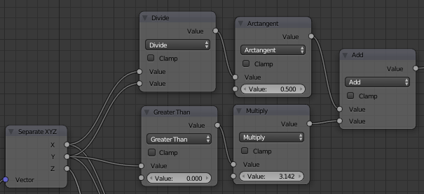
Firstly, the angle to the origin - which I'llthis can be calculated using standard trigonometry using the arctangent, since tan(angle) = x / y so atan(x / y) = angle. This will only give a result over half the rotation before repeating for the other half, so we need to include additional nodes to add 180 degrees (or 'pi' radians) for the second half of the rotation - ie, when the sign of the y-coordinate flips between positive and negative. This yeilds the following nodes to determine the angle from the coordinates :

get angle

The distance from the origin can be determined simply using the Dot Product and a Power(0.5) maths node (again, passing the same vector into both inputs of the Dot Product calculates the square of the distance, the power(0.5) takes the square root, resulting in due coursethe actual length of the vector) :

get distance

The modulo function is used to determine which rotation around the spiral arm is the closest to this point and this, adjusted based on the angle (calculated as above) gives us the point on the spiral that is closest to this sample point in the volume.

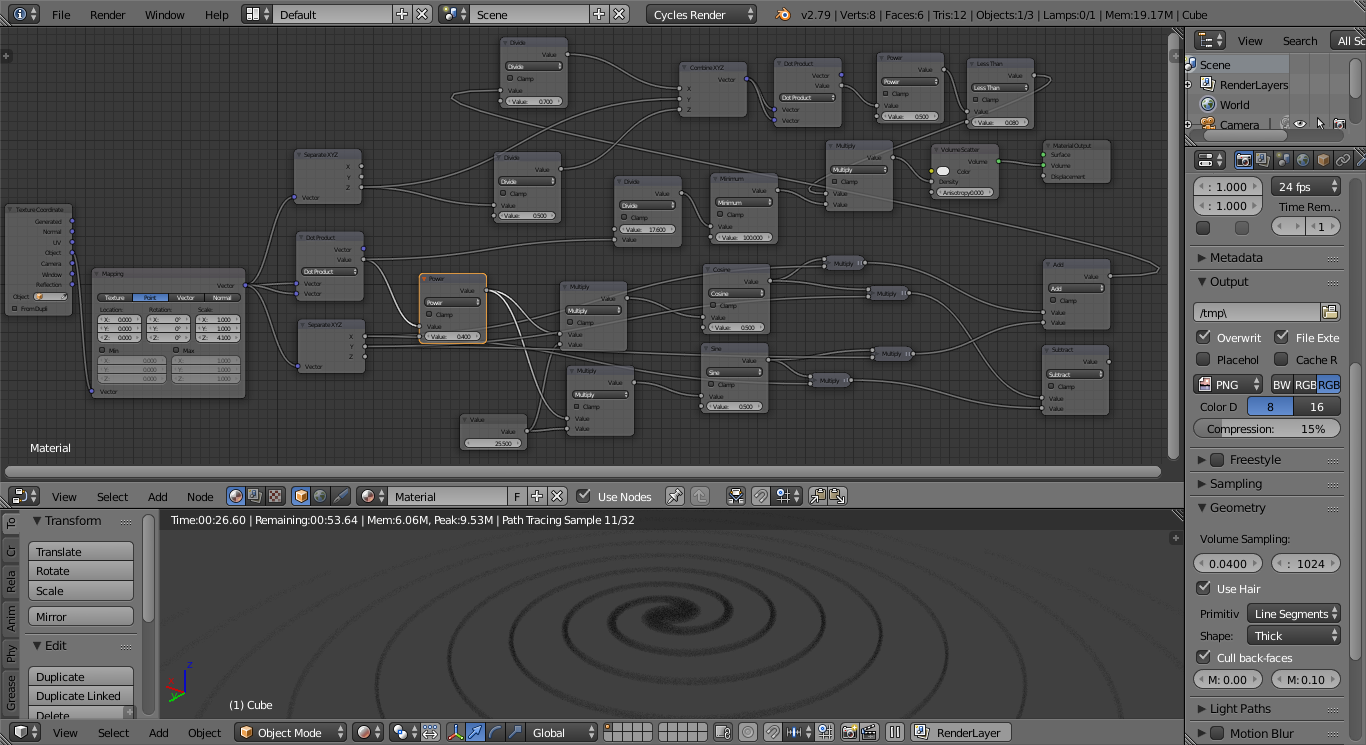
We can add in some nodes to allow the results to be adjusted (eg, varying the thickness based on the distance so that it thins out towards the ends of the arms) and this produces the following material :

spiral revisited - full material

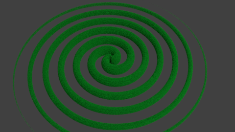
spiral revisited - result

To make it easier to reuse, we can create a node group that takes the vector in the volume, the desired properties of the spiral (number of "arms", "twistedness") :

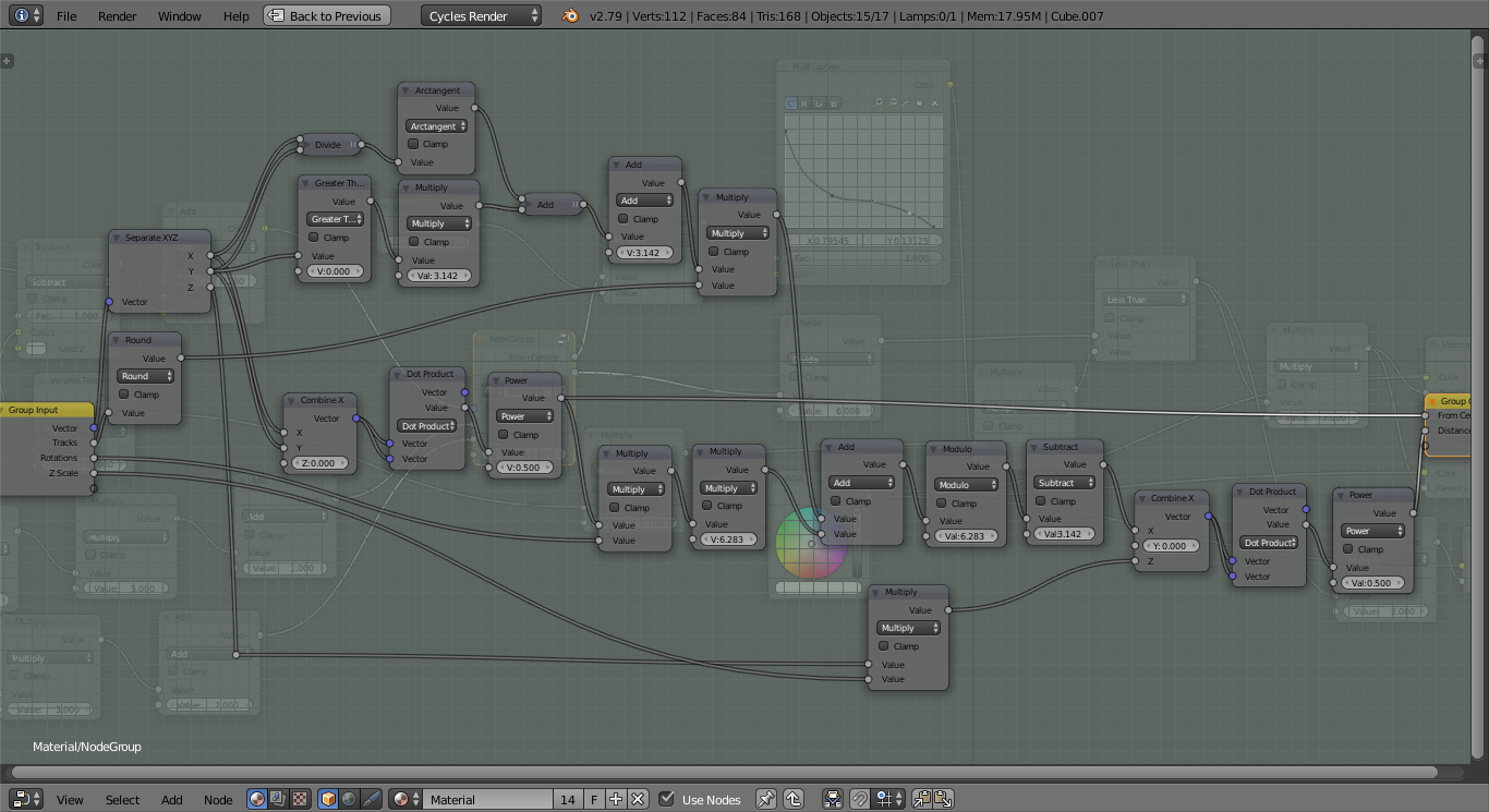
node group internals

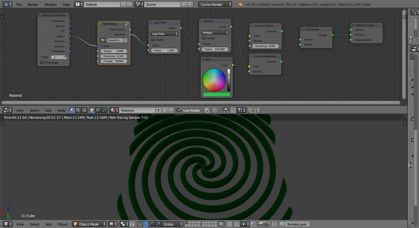
This can be used as follows :

using node group and results

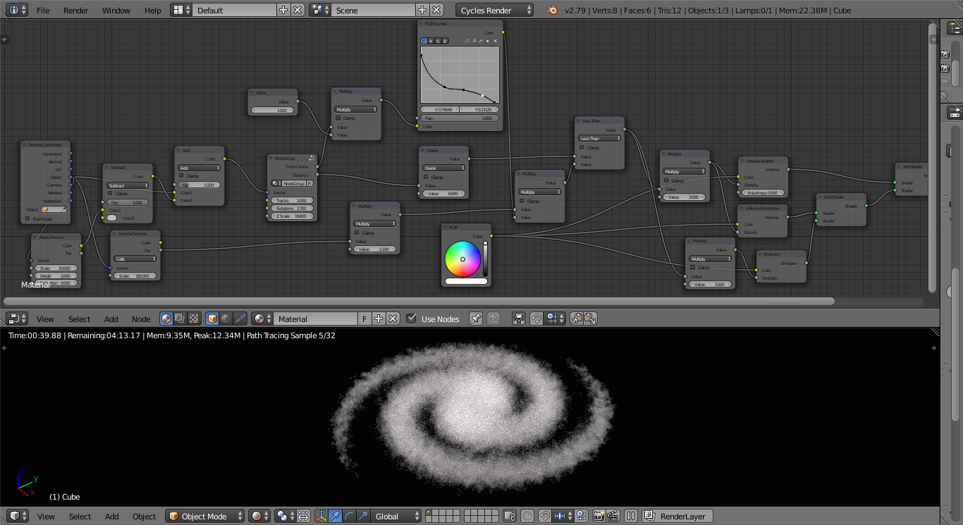
Now you have a configurable volumetric spiral, the only remaining challenge is to use this to produce a believable galaxy :

image - single galaxy

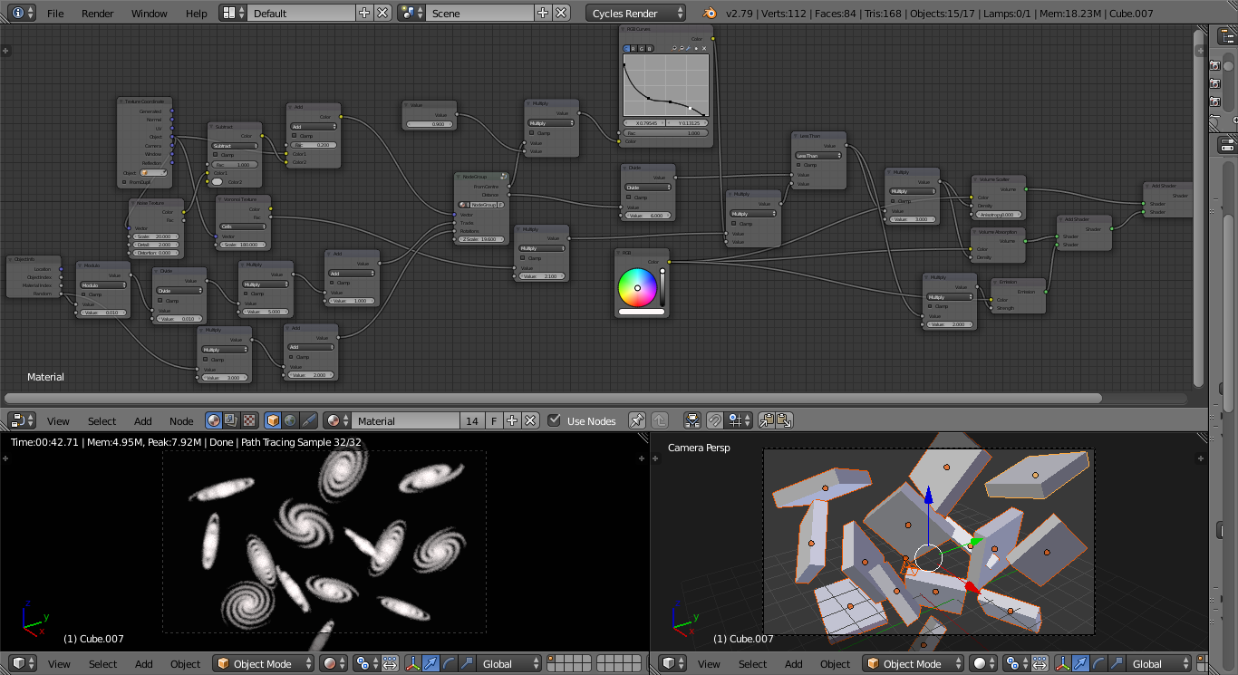
To make each galaxy different we can use the Object Info 'Random' property to generate the spiral properties to produce the following result :

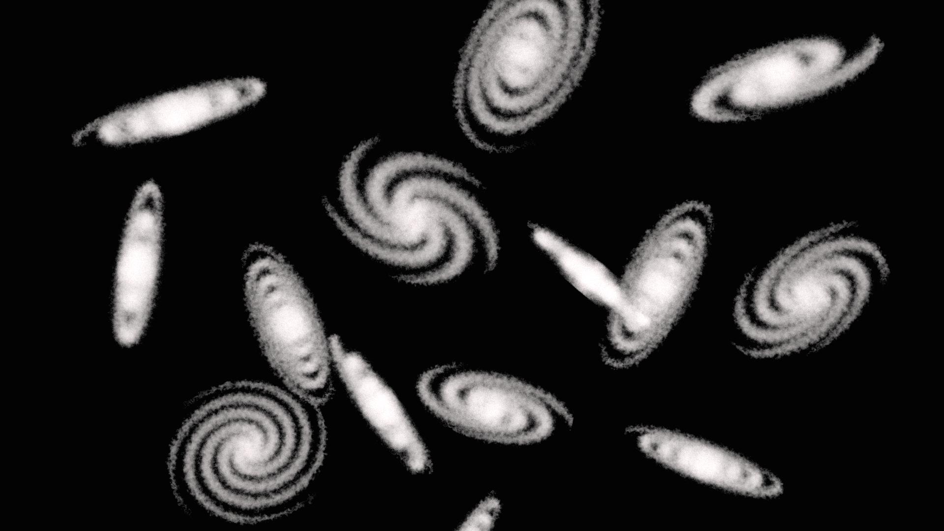
galaxies2 - material and result

Blend file included

One method is to create a volumetric cylinder and distort it by rotating it around the origin by an amount that varies based on the distance from the origin.

Note that this is a very much "brute force" method of generating a spiral - and it can only produce a spiral with two "arms" (unless you were to truncate the spiral at y = 0 - in which case it would have a single "arm"). There is a better (more mathematical) method - which I'll add in due course.

Final result final result


One method is to create a volumetric cylinder and distort it by rotating it around the origin by an amount that varies based on the distance from the origin.

Note that this is a very much "brute force" method of generating a spiral - and it can only produce a spiral with two "arms" (unless you were to truncate the spiral at y = 0 - in which case it would have a single "arm").


Another approach is to generate the spiral directly - rather than distorting a cylinder - by calculating for each 'sample point' the closest point that lies on the centreline of the spiral. Calculating the distance to the centreline of the spiral allows us to determine whether that point lies within the spiral. This produces more versatile results and does not require manual adjusting of the thickness. It can also generate spirals with any number of 'arms'.

To achieve this we need to be able to calculate the closest point on the centreline of the spiral. For any point in the volume we can determine a number of things about this 'closest point'

  1. It lies on the 'plane' of the spiral - in our case we can use z = 0
  2. The sample point in the volume is along the direction of the Normal of the centreline from the closest point - ie, it points away from or towards the origin.
  3. The centreline distance from the origin varies based on the angle that the spiral centreline makes in the plane of the spiral (and, therefore, also its normal).

This allows us to calculate the closest point of the centreline for any point in the volume. Once we know the 'closest point' we can simply calculate the distance between it and the sample point to determine whether that point in the volume lies inside or outside the spiral (based on our desired "arm" radius).

Firstly, the angle to the origin - this can be calculated using standard trigonometry using the arctangent, since tan(angle) = x / y so atan(x / y) = angle. This will only give a result over half the rotation before repeating for the other half, so we need to include additional nodes to add 180 degrees (or 'pi' radians) for the second half of the rotation - ie, when the sign of the y-coordinate flips between positive and negative. This yeilds the following nodes to determine the angle from the coordinates :

get angle

The distance from the origin can be determined simply using the Dot Product and a Power(0.5) maths node (again, passing the same vector into both inputs of the Dot Product calculates the square of the distance, the power(0.5) takes the square root, resulting in the actual length of the vector) :

get distance

The modulo function is used to determine which rotation around the spiral arm is the closest to this point and this, adjusted based on the angle (calculated as above) gives us the point on the spiral that is closest to this sample point in the volume.

We can add in some nodes to allow the results to be adjusted (eg, varying the thickness based on the distance so that it thins out towards the ends of the arms) and this produces the following material :

spiral revisited - full material

spiral revisited - result

To make it easier to reuse, we can create a node group that takes the vector in the volume, the desired properties of the spiral (number of "arms", "twistedness") :

node group internals

This can be used as follows :

using node group and results

Now you have a configurable volumetric spiral, the only remaining challenge is to use this to produce a believable galaxy :

image - single galaxy

To make each galaxy different we can use the Object Info 'Random' property to generate the spiral properties to produce the following result :
galaxies2 - material and result

Blend file included

added 187 characters in body
Source Link
Rich Sedman
  • 45.2k
  • 2
  • 109
  • 233

One method is to create a volumetric cylinder and distort it by rotating it around the origin by an amount that varies based on the distance from the origin.

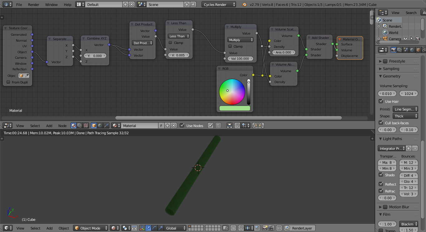
First, create a volumetric cylinder. This is achieved by calculating the distance from the origin in just two of the three dimensions (it's effectively a circle projected along the remaining axis). This can be achieved using the Dot Product vector maths node using the following arrangement (assuming the cylinder is to be produced along the 'y' axis) :

volumetric cylinder

The Dot Product used in this way (with the same vector on both inputs) produces the square of the length of the vector. The following Power(0.5) node calculates the square root of the squared length - ie, the actual vector length. The Less Than node controls the radius of the cylinder.

NOTE : The Geometry Volume Sampling step size has been decreased to 0.010 in this example in order to improve the volumetric precision (at the expense of render time). Also, the Light Paths Volume Bounces has been increased from zero to 3 to allow multiple scatter bounces (see the properties panel at the right-hand side of the image).

In order to rotate the cylinder we need to use a rotation matrix similar to

X = x * cos(angle) + y * sin(angle)
Y = -x * sin(angle) + y * cos(angle)

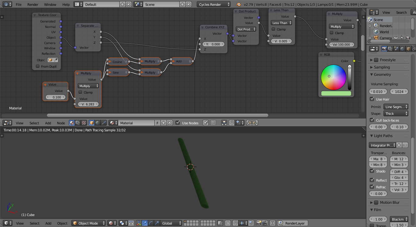
Since we already know that the 'y' coordinate is irrelevant (since the cylinder is unchanged regardless of where along the y-axis it is viewed) we can simplify this by only actually needing to calculate in the X coordinate. This is therefore achieved with the following additional nodes :

rotated volumetric cylinder

NOTE : Varying the Value input node rotates the volumetric cylinder. The Multiply node multiplies the input value by 2*pi, converting the input value to radians - so 0.0 to 1.0 produces one whole rotation.

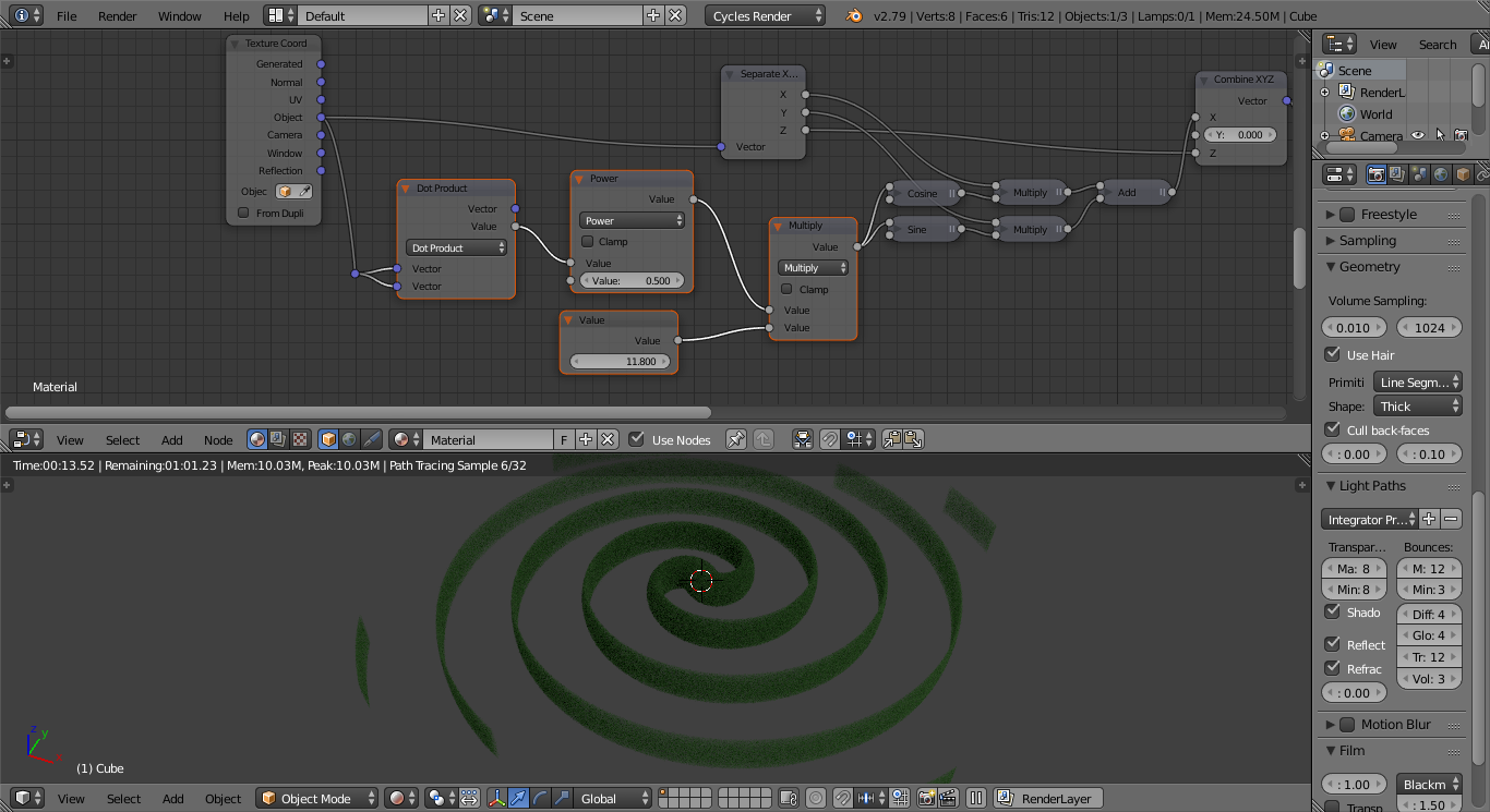
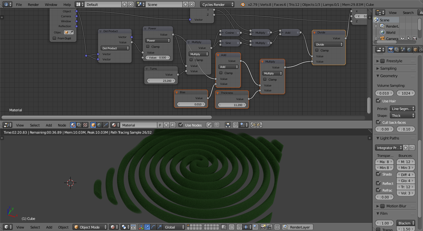
To produce a spiral we can simply vary the rotation based on the distance from the origin. This can be achieved with another Dot Product/Power node combination with the following additional nodes :

spiral (but flattened)

Increasing the Value input varies the number of turns of the spiral.

Note, however, that the spiral is stretched into a thin ribbon as it is rotated. To counteract this we can simply add additional nodes to vary the thickness of the original "cylinder" based on the distance from the origin :

spiral

Thickness controls how much the cylinder is scaled based on the distance and Bias controls the starting thickness at the centre of the spiral (prevents it collapsing down to a point).

Blend file included

Note that this is a very much "brute force" method of generating a spiral - and it can only produce a spiral with two "arms" (unless you were to truncate the spiral at y = 0 - in which case it would have a single "arm"). There is a better (more mathematical) method - which I'll add in due course.

One method is to create a volumetric cylinder and distort it by rotating it around the origin by an amount that varies based on the distance from the origin.

First, create a volumetric cylinder. This is achieved by calculating the distance from the origin in just two of the three dimensions (it's effectively a circle projected along the remaining axis). This can be achieved using the Dot Product vector maths node using the following arrangement (assuming the cylinder is to be produced along the 'y' axis) :

volumetric cylinder

The Dot Product used in this way (with the same vector on both inputs) produces the square of the length of the vector. The following Power(0.5) node calculates the square root of the squared length - ie, the actual vector length. The Less Than node controls the radius of the cylinder.

NOTE : The Geometry Volume Sampling step size has been decreased to 0.010 in this example in order to improve the volumetric precision (at the expense of render time). Also, the Light Paths Volume Bounces has been increased from zero to 3 to allow multiple scatter bounces (see the properties panel at the right-hand side of the image).

In order to rotate the cylinder we need to use a rotation matrix similar to

X = x * cos(angle) + y * sin(angle)
Y = -x * sin(angle) + y * cos(angle)

Since we already know that the 'y' coordinate is irrelevant (since the cylinder is unchanged regardless of where along the y-axis it is viewed) we can simplify this by only actually needing to calculate in the X coordinate. This is therefore achieved with the following additional nodes :

rotated volumetric cylinder

NOTE : Varying the Value input node rotates the volumetric cylinder. The Multiply node multiplies the input value by 2*pi, converting the input value to radians - so 0.0 to 1.0 produces one whole rotation.

To produce a spiral we can simply vary the rotation based on the distance from the origin. This can be achieved with another Dot Product/Power node combination with the following additional nodes :

spiral (but flattened)

Increasing the Value input varies the number of turns of the spiral.

Note, however, that the spiral is stretched into a thin ribbon as it is rotated. To counteract this we can simply add additional nodes to vary the thickness of the original "cylinder" based on the distance from the origin :

spiral

Thickness controls how much the cylinder is scaled based on the distance and Bias controls the starting thickness at the centre of the spiral (prevents it collapsing down to a point).

Blend file included

Note that this is a very much "brute force" method of generating a spiral - and it can only produce a spiral with two "arms" (unless you were to truncate the spiral at y = 0 - in which case it would have a single "arm"). There is a better (more mathematical) method - which I'll add in due course.

added 2319 characters in body
Source Link
Rich Sedman
  • 45.2k
  • 2
  • 109
  • 233

This is unfinished and certainly needs some tidying up but hereOne method is a solution to producecreate a true spiralvolumetric cylinder and distort it by rotating the object coordinatesit around the origin by an amount that varies based on the distance from the origin. As I say

First, create a volumetric cylinder. This is achieved by calculating the distance from the origin in just two of the three dimensions (it's effectively a circle projected along the remaining axis). This can be achieved using the Dot Product vector maths node using the following arrangement (assuming the cylinder is to be produced along the 'y' axis) :

volumetric cylinder

The Dot Product used in this needs some refinement and tidying upway (with the same vector on both inputs) produces the square of the length of the vector. The following Power(0.5) node calculates the square root of the squared length - and for a convincing galaxy would need added noise displacementie, the actual vector length. The Less Than node controls the radius of the cylinder.

NOTE : The Geometry Volume Sampling step size has been decreased to make it much less regular0. I'll try and refine010 in this example in order to improve the near future and post updatesvolumetric precision (at the expense of render time). Also, the Light Paths Volume Bounces has been increased from zero to 3 to allow multiple scatter bounces (see the properties panel at the right-hand side of the image).

In order to rotate the cylinder we need to use a rotation matrix similar to

X = x * cos(angle) + y * sin(angle)
Y = -x * sin(angle) + y * cos(angle)

Since we already know that the 'y' coordinate is irrelevant (since the cylinder is unchanged regardless of where along the y-axis it is viewed) we can simplify this by only actually needing to calculate in the X coordinate. This is therefore achieved with the following additional nodes :

rotated volumetric cylinder

NOTE : Varying the Value input node rotates the volumetric cylinder. The Multiply node multiplies the input value by 2*pi, converting the input value to radians - so 0.0 to 1.0 produces one whole rotation.

To produce a full breakdownspiral we can simply vary the rotation based on the distance from the origin. This can be achieved with another Dot Product/Power node combination with the following additional nodes :

spiral (but flattened)

Increasing the Value input varies the number of turns of the spiral.

Note, however, that the spiral is stretched into a thin ribbon as it is rotated. To counteract this we can simply add additional nodes to vary the thickness of the original "cylinder" based on the distance from the origin :

spiral

Blend file included

Note that this is a very much "brute force" method of generating a spiral - and explanation but thought I'd include it can only produce a spiral with two "arms" (unless you were to truncate the spiral at isy = 0 - in which case it's usefulit would have a single "arm"). There is a better (more mathematical) method - which I'll add in the meantimedue course.

enter image description here

This is unfinished and certainly needs some tidying up but here is a solution to produce a true spiral by rotating the object coordinates around the origin based on the distance from the origin. As I say, this needs some refinement and tidying up - and for a convincing galaxy would need added noise displacement to make it much less regular. I'll try and refine this in the near future and post updates along with a full breakdown and explanation but thought I'd include it at is in case it's useful in the meantime.

enter image description here

One method is to create a volumetric cylinder and distort it by rotating it around the origin by an amount that varies based on the distance from the origin.

First, create a volumetric cylinder. This is achieved by calculating the distance from the origin in just two of the three dimensions (it's effectively a circle projected along the remaining axis). This can be achieved using the Dot Product vector maths node using the following arrangement (assuming the cylinder is to be produced along the 'y' axis) :

volumetric cylinder

The Dot Product used in this way (with the same vector on both inputs) produces the square of the length of the vector. The following Power(0.5) node calculates the square root of the squared length - ie, the actual vector length. The Less Than node controls the radius of the cylinder.

NOTE : The Geometry Volume Sampling step size has been decreased to 0.010 in this example in order to improve the volumetric precision (at the expense of render time). Also, the Light Paths Volume Bounces has been increased from zero to 3 to allow multiple scatter bounces (see the properties panel at the right-hand side of the image).

In order to rotate the cylinder we need to use a rotation matrix similar to

X = x * cos(angle) + y * sin(angle)
Y = -x * sin(angle) + y * cos(angle)

Since we already know that the 'y' coordinate is irrelevant (since the cylinder is unchanged regardless of where along the y-axis it is viewed) we can simplify this by only actually needing to calculate in the X coordinate. This is therefore achieved with the following additional nodes :

rotated volumetric cylinder

NOTE : Varying the Value input node rotates the volumetric cylinder. The Multiply node multiplies the input value by 2*pi, converting the input value to radians - so 0.0 to 1.0 produces one whole rotation.

To produce a spiral we can simply vary the rotation based on the distance from the origin. This can be achieved with another Dot Product/Power node combination with the following additional nodes :

spiral (but flattened)

Increasing the Value input varies the number of turns of the spiral.

Note, however, that the spiral is stretched into a thin ribbon as it is rotated. To counteract this we can simply add additional nodes to vary the thickness of the original "cylinder" based on the distance from the origin :

spiral

Blend file included

Note that this is a very much "brute force" method of generating a spiral - and it can only produce a spiral with two "arms" (unless you were to truncate the spiral at y = 0 - in which case it would have a single "arm"). There is a better (more mathematical) method - which I'll add in due course.

Source Link
Rich Sedman
  • 45.2k
  • 2
  • 109
  • 233
Loading