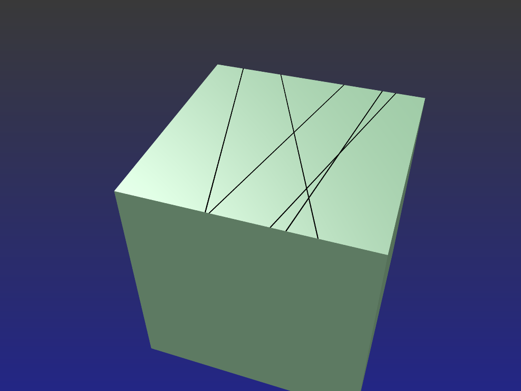
To draw clearly defined and 'arbitrarily' chosen lines on the surface of an object, one effective method would be to simply lay one or more 2D planes onto it's surface(s).
Add the first plane and -
Reduce it's thickness so it ends up as a very thin line.
Give it a material slot and colour it black, remove it's specular so it won't reflect light.
Add as many of these as you wish, (or duplicate the first) and drag them around as required
Once positioned correctly (a tad above the cube's surface), either parent or join them to the cube when animation is involved. (so they don't get left behind)
You could as an alternative subdivide the cube's surface to form the lines but that may introduce unnecessary complication at some point down the track. The planes on the other hand are independent and can be removed, reshaped, and changed about at will.
-=====-
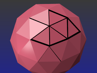
The ico sphere was treated a little differently but again the 'lines' end up as a separate frame and is simply laid against the sphere.
The procedure -
Some ico surfaces are selected in Edit Mode, then duplicated.
The copied surfaces were (P) "Parted by selection" and moved to another layer to make it easier to work with.
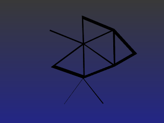
In Edit mode these faces are all removed so we only have a wireframe. (2nd image)
The wireframe was duplicated and "Shrunk" (scaled down) enough to give us double edging. (this is where the lines' thickness is adjusted. Lines can be given their own individual thickness if required)
Both edge-sets were "Joined" (CTL-J) and their vertices filled (F) at the ends so we get enclosed areas which can be filled in to form surfaces. These are all coloured black.
Combining the two layers give us the overlay picture. The frame is moved a tad out from the Ico's surface so we don't have surfaces conflicting and tearing each other.
Some ico panels were deliberately left open with only one or two edges included in the end frame. This was done because of the word 'arbitrary' used in your your question. You're not bound or limited to which edges are to be drawn, which aren't, or each line's thickness.
Parenting the frame to the ico sphere is a good idea.
EDIT:
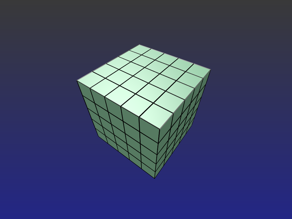
On reading @cegaton's links in the comments above, the wireframe modifier idea could be combined with what I've posted here to give full control over the lines themselves as to which will remain, their size and thickness and even individual line colours.
Duplicate the 1st model, move that into a 2nd layer and in Edit mode subdivide as required.
Expand that so it's easily distinguishable from the original when viewed together.
Apply the wireframe modifier to the clone so we have a mesh cage.
Colour all or individual faces of the wireframe and re-combine the two models again but don't join them, just parent the wireframe to the original model.
Rescale the clone so it wraps neatly around the original.
We get this -
When the original model is to be textured there'll be no interference from the cage lines. These too can be modified at will and again, without affecting the original.


