Here is how I solved this.
(Coordinates written as 1,2,3 refer to X:1 Y:2 Z:3, for example.)
Setting up the "Cube Cam"
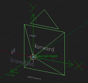
Add a Camera and an Empty at location 0,0,0 and set rotation of each to 90,0,0 degrees. If you choose "Arrows" for the Empty display type it may help avoid confusion later.
Parent the Camera to the Empty. The reasons for rotating and then parenting in this order are so that the Camera's coordinates will match the reference image above, and so that the Empty's -Z will point in the same direction as the Camera's when the Camera is facing forward.
The Empty serves to allows the Camera to be easily repositioned, because the Camera's keyframed rotation will be relative to the Empty, not the World.
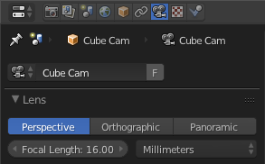
Set the Camera's Focal Length to 16mm (or 90° Field of View). This is necessary for the "faces" of the cube map to touch exactly.
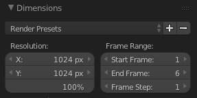
Set your render dimensions to a power of two, such as 512, 1024, etc.
Leave the Start Frame at 1. Set the End Frame to 6. There will be one frame for capturing each direction of a cube's faces.
Keyframe the Camera's rotation accordingly in these frame numbers:
- 90, 0, 90 (left)
- 90, 0, 180 (backward)
- 90, 0, 270 (right)
- 0, 0, 0 (down)
- 180, 0, 0 (up)
- 90, 0, 0 (forward)
Optionally, you can add a guide object containing text labeling the directions (visible in the viewport, but not in renders), and parent this to the empty as well. And you can group these three objects (Camera, Empty, text guide) together, so that they can be easily appended to other .blend files.
At this point the Cube Cam setup can be appended into any .blend file.
After appending, from within the new .blend:
- Go to frame 6, where the Camera is facing forward.
- Make sure the Cube Cam is the Active Camera, by selecting it and choosing View > Cameras > Set Active Object as Camera.
- Use the Empty to position the "Cube Cam".
- Set the frame range from 1 to 6, and specify the Output file name to be something like "cube_tile_".
- Set the Render Dimensions for X and Y to a power of 2, for example, 1024x1024. This will be the resolution of each of the 6 tiles.
- When ready to render, click the Animation button.
This method of rendering directly from the environment scene is quick and easy, but there is still some distortion that shows up, revealing the cube shape of the cube map if you look closely. The way to eliminate this is to first render an equirectangular (or mirror ball) environment map, and then render that to a cube map.
Equirectangular Map to Cube Map
First, let's review the steps for creating an equirectangular map to begin with. It's pretty simple.
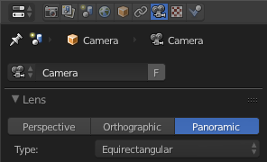
Step 1: Adjust the Camera settings to be Panoramic, then choose Equirectangular for the type.
Step 2: Set the render Resolution so that X is twice that of Y.
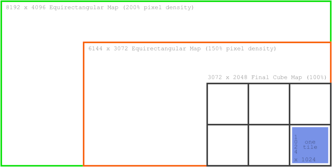
Choose a resolution that is significantly higher (perhaps double) the pixel detail of what one of the final cube map's tiles will be. So if one tile of the cube map will be 1024x1024, and two of those tiles will be stacked on the Y axis (doubled), then doubling that to 8192x4096 would give 200% pixel density on Y (and 266.6% on X because of the difference in ratio).
Here's a diagram to make it easier to understand:
Render!
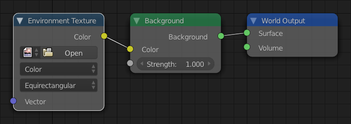
Now, back in the Cube Cam .blend file, in the World context  click the Use Nodes button and go to the Node Editor. Create the node setup for a panoramic environment:
You won't need many samples for this. I did some testing and found that no sample count higher than 20 produces any visible improvement, so I recommend rendering at 20 samples.
Save this .blend file to reuse later.
In the Environment Texture node, click Open to load a specific panoramic image, and render it out as an animation to 6 cube map images. 
You can use an image editor such as GIMP, or Blender's compositor to combine the 6 image tiles into one cube map image. Two advantages of doing this in the compositor are that you won't need to rely on other software besides Blender, and you won't need to manually position each tile every time you create a cube map - once you've set it up, it's an automated process.
Putting it All Together With Compositing
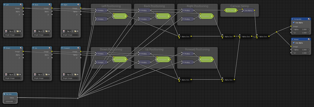
In a new .blend (or new Scene, if you prefer), create this node setup in the Compositor:
Let's examine it in more detail.
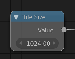
The Value node for "Tile Size" should be set to the X and Y resolution of one tile (or you can think of it as one "face" of the cube map). So the final image resolution should be this amount times 3 across (X) and this times 2 down (Y). For example, if one cube tile is 1024 pixels, the render resolution should be set to 3072x2048. You don't even have to do any math in your head - just type 1024*3 into input field X, and 1024*2 into input field Y. Blender will calculate it for you. (Okay, maybe 1024*2 is easy, but you can surely see how this shortcut is useful.)
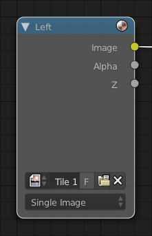
Each Image node is set to load a tile of the cube map (1~6):
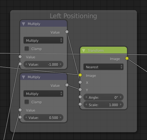
These six nodes determine the position of each tile in relation to the whole image, or "canvas":
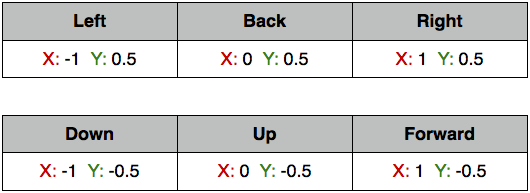
Set the Multiply nodes to the following values:
The Alpha Over nodes are just for layering the tiles, while preserving transparency (in case you ever need to composite a cube map that contains alpha data). These can be left at their default settings.
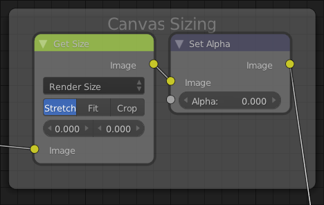
A Scale node, which I have labeled "Get Size" takes in the image data of one tile, then scales it to the size of the render (which, as mentioned, should be three times across and two times down in proportion to the size of one tile).
That image data is then sent through a Set Alpha node because the image data is not necessary - all we need it for is getting the correct dimensions. What we get out of the Set Alpha node is a transparent "canvas" that is the size of the render dimensions.
So that's basically it. You can render the image and it will be composited!
I've published a toolkit for creating cube maps to Blend Swap under a CC-0 license and it should be approved soon. Once it is I will post the link here.

