16
$\begingroup$

mesh in blender

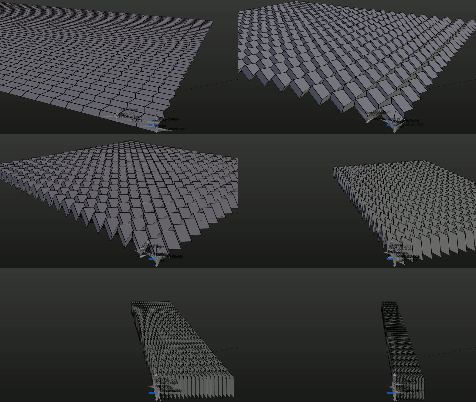
I'm hoping to find advice here for simulating the Miura origami in Blender. I have searched quite thoroughly on methods and have only come as far as my failed attempt in my attached image above. The Miura fold is based on units of two-way folds, not only do the folds perform as hinges, they also influence the whole origami system.

In my attempt I'm using bones, however they force the whole mesh to deform. To prevent this, is it necessary to have the mesh as units of rigid bodies so that they adopt physical reactions?

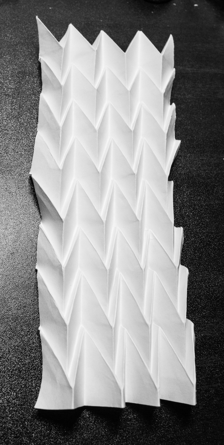
Below is my paper fold for reference. paper fold reference

$\endgroup$
2
  • 3
    $\begingroup$ Do you seek a real simulation or an animation ? $\endgroup$
    – lemon
    Commented Jul 16, 2016 at 15:01
  • $\begingroup$ Hi, thank you for your question, I need a simulation, so now that I think about it, bones might have been the wrong approach..? $\endgroup$
    – Chlyxu
    Commented Jul 17, 2016 at 2:32

2 Answers 2

9
$\begingroup$

Boy that one is tricky, but I think I found a (physically correct) solution to the question. First of all, the Blend file:

EDIT: more flexible version here, Array now works in both directions:

screenshot here:
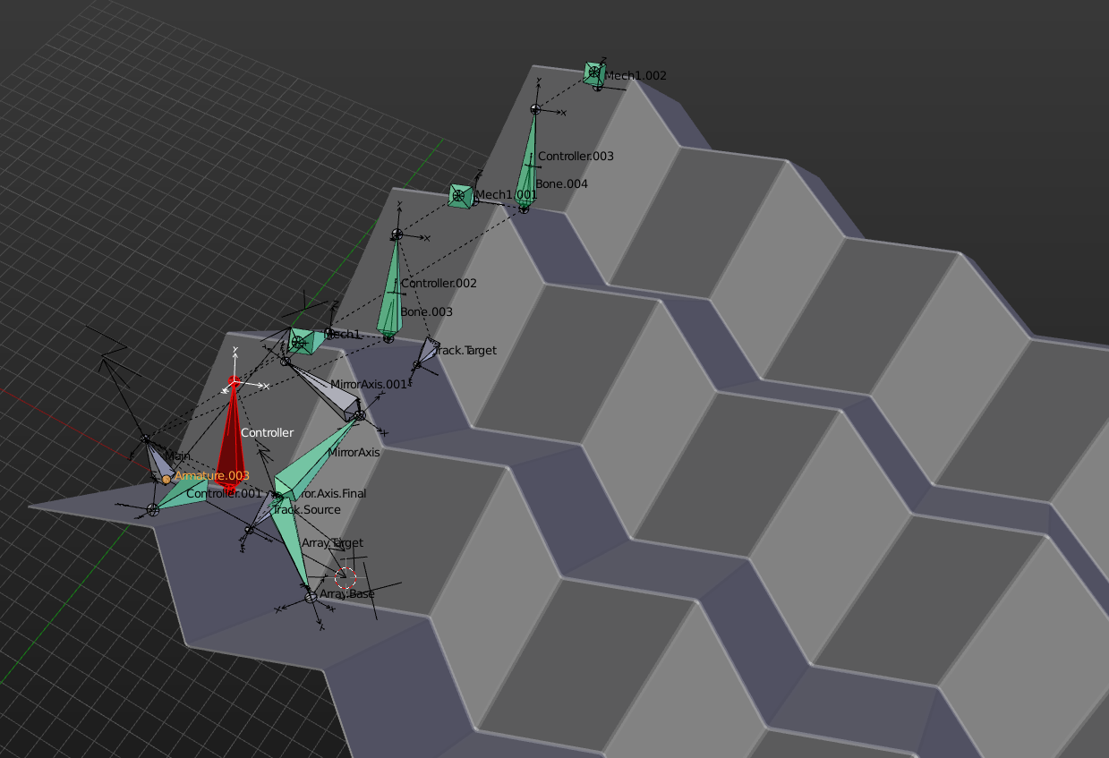
final rig

animated version

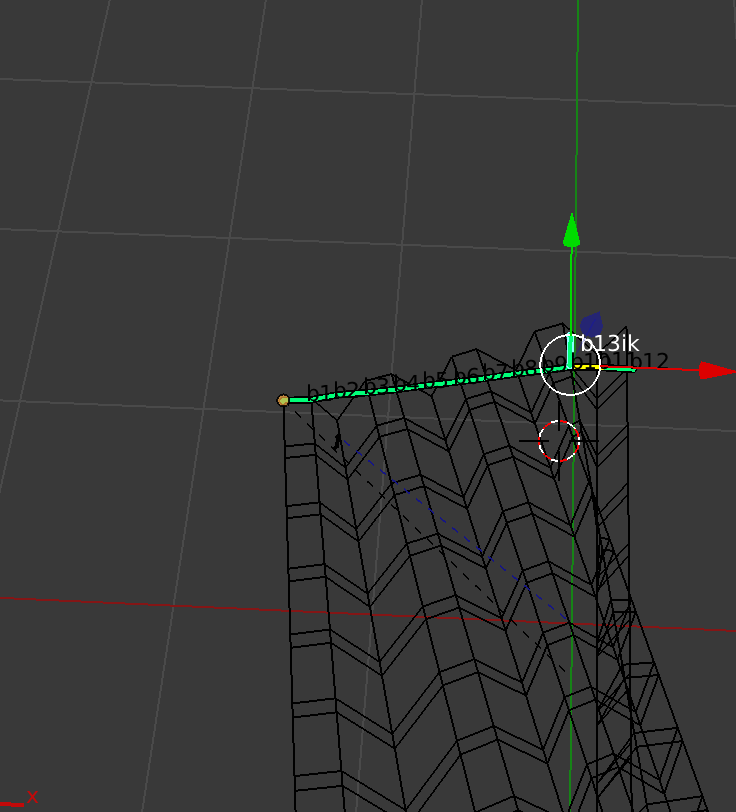
Desperately trying to rig this the whole afternoon with placing bones at the edges of the geometry, I decided to rather play origami instead. When I looked at the object in motion then, I noticed that the folding itself can be seen as triggered by one face rotating around the edge of its mirrored counterpart. Then I tried placing the first controller bone exactly perpendicular to that edge, and went on rigging from there:
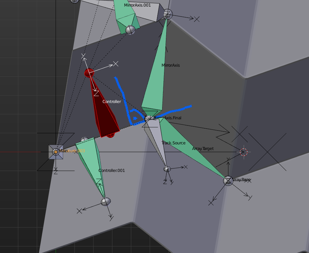
first bone perpendicular to edge

The next Bone, Mech1, which is also perpendicular to the edge, copies the rotation from its parent, the controller bone, but inverts the result so it points back down instead of up. You also have to set the mode to Pose Space, Local Space won't work the same way:

copy rotation

Now two faces can already fold correctly. To continue, insert the same chain again for the next faces, but keep in mind that an intermediate bone is needed (Bone.003) to free the rotation channel of the next mech bone. Bone.003 is a child of Mech1, Mech1.001 a child of Controller.001. The bones simply copy the rotations of Controller and Mech1:

creating other rows of bone chains

At this point I added an Armature and some weights to the mesh to see the movement of the first row of faces. Now the difficult part: Because of the qay I rigged it, the mesh starts to rotate in top view while folding. So Mirror and Array modifier have no simple axis to work on. For the mirror and array modifiers, we need two empties to act as center point and direction. To find the symmetry plane, I added two helper bones, which are childs of Controller and Controller.002. A MirrorAxis bone points from Track.Source to Track.Target using a TrackTo constraint:
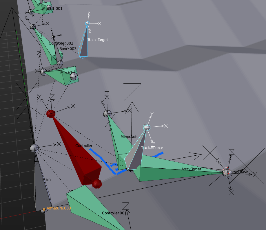
enter image description here

I then created an empty and parented it to the MirrorAxis bone. Doing that, I get the correct orientation and location, and in the mirror modifier I now have an object, the empty, which I can feed into the stack:
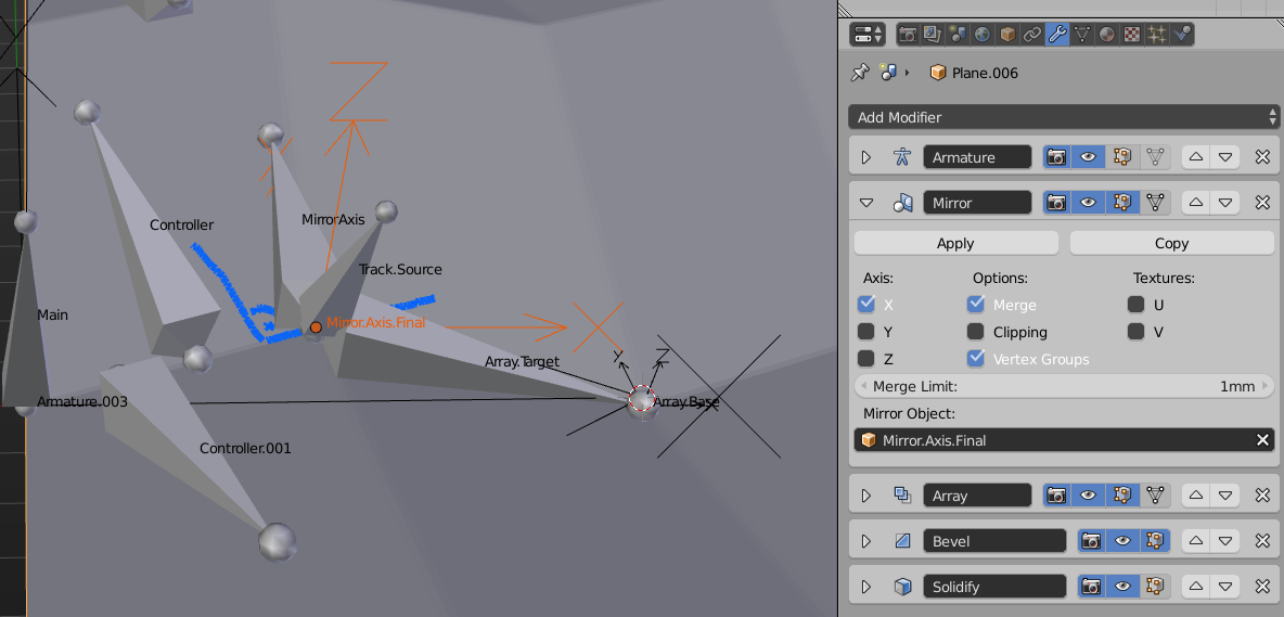
dynamic mirror axis

At this point, the mesh is already mirrored correctly and can be tested. But it is not possible to use the same empty for the array, as the transformation is off and it has a rotation to it. So another helper bone is needed, which in the end has to point at the corner of the folded mesh all the time:
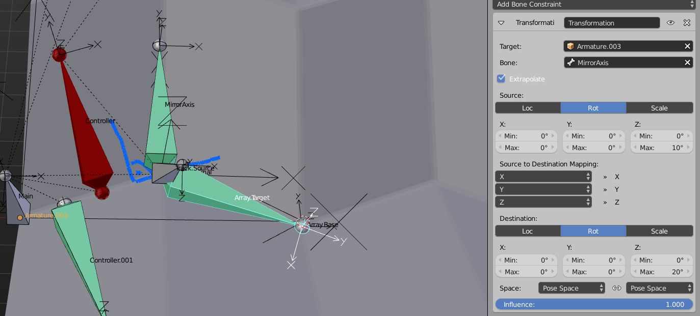
enter image description here

I used a Transformation constraint to get this to work. In Edit Mode i had placed the bone like it should be already. Then the logic is like this: Whenever the MirrorAxis bone receives a rotation by the TrackTo constraint, the Array.Target bone shall receive twice as much rotation (the mirror axis rotates by x, the mirrored bone has to rotate by 2 * x). To the tip of that bone I parented another empty, and used it in the Object Offset field of the array. Done!

I probably could have used a second array instead of a chain of bones for the first direction, but the idea came much later to me. If I had done that, the rig would be very flexible, as you can decide for each direction on how many faces you want. EDIT: I provided a second file which gets rid of unnecessary bones and gives you the choice on how many faces you want in both directions.

$\endgroup$
3
  • $\begingroup$ holy, wow, um, I think this is what I was attempting to do in the beginning, thanks so much for even providing the files for me to study. It will take me some time to understand this system, please let me get back to you after that. However, just looking at prospects, do you think this method can be followed by cloth physics where the Miura structure can act semi-rigid (really - as paper), and hang from - lets say - a curtain rod? $\endgroup$
    – Chlyxu
    Commented Jul 17, 2016 at 23:36
  • $\begingroup$ I'm not 100% sure if I get your question right. Do you want to use the rigged model, and apply a cloth simulation on top of that? Or is it acceptable to bring the rigged mesh into a certain position, apply the armature (so the mesh is kind of 'frozen' in that state), and then go for cloth or (which might work as well) softbody simulation? $\endgroup$
    – aliasguru
    Commented Jul 18, 2016 at 7:12
  • $\begingroup$ Ideally, to apply a cloth simulation on top of the rigging, so that - maybe - the bones react to gravity....I have already tried soft-body simulation using hooks and displacement, it comes out looking something like what I need, but I know displacement is simply a texture on the cloth, so if the rigged method can "hang", it would be awesome. $\endgroup$
    – Chlyxu
    Commented Jul 19, 2016 at 13:36
11
$\begingroup$

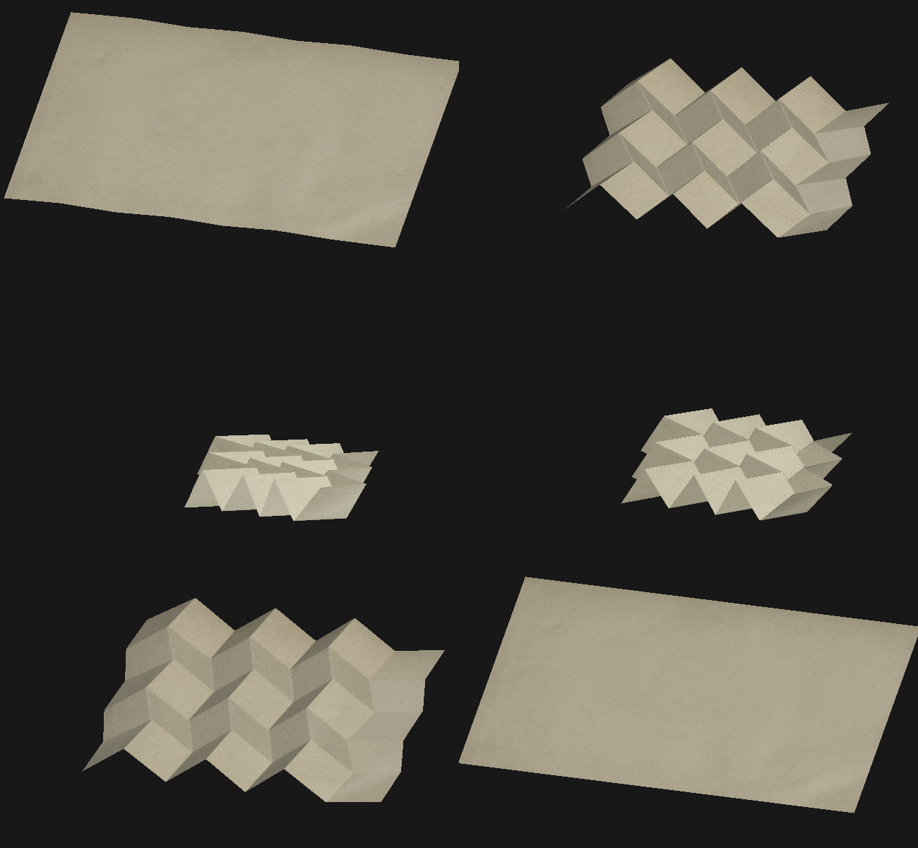
animated gif - final result

I was able to create that animation just using shape keys.

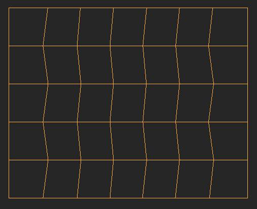
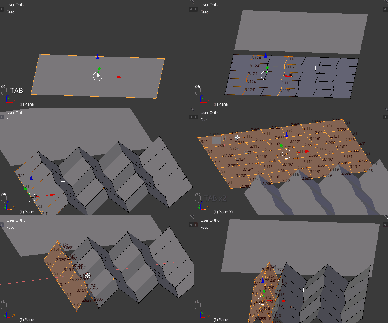
  1. Start out with a plane that has the same geometry as the folds in a Miura fold.
    mesh
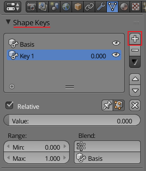
  2. Add two shape keys on that mesh. The first will be the "Basis," the second will be the one in which you edit the mesh. (I used more then two, but two will work fine.)
    enter image description here
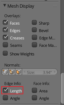
  3. Tab in to Edit mode and start moving the edges together. The only tricky part is keeping the edges the same length. You will need to turn on Length in the Mesh Display heading of the properties region. (I duplicated the unedited mesh so I could check the edge lengths.)
    properties region > mesh display

    1. Start by selecting every second edge loop and moving it up along the Z a bit less then the length of the edges. (In my mesh the shortest edge was about 2.66, so I moved the edges up 2.5.)
    2. Starting at the end, select each edge loop and move it along the X until the lengths match the original length. (It does not have to be perfect, in the gif I'm sure not.) Continue moving the edges closer together until you are done with that axis.
      Simply do the same thing for the other axis. Starting at the top (or bottom) select each edge loop and move it along the Y axis until it is the same length as the original.

In this gif I only do three edges, just because it is all the same.
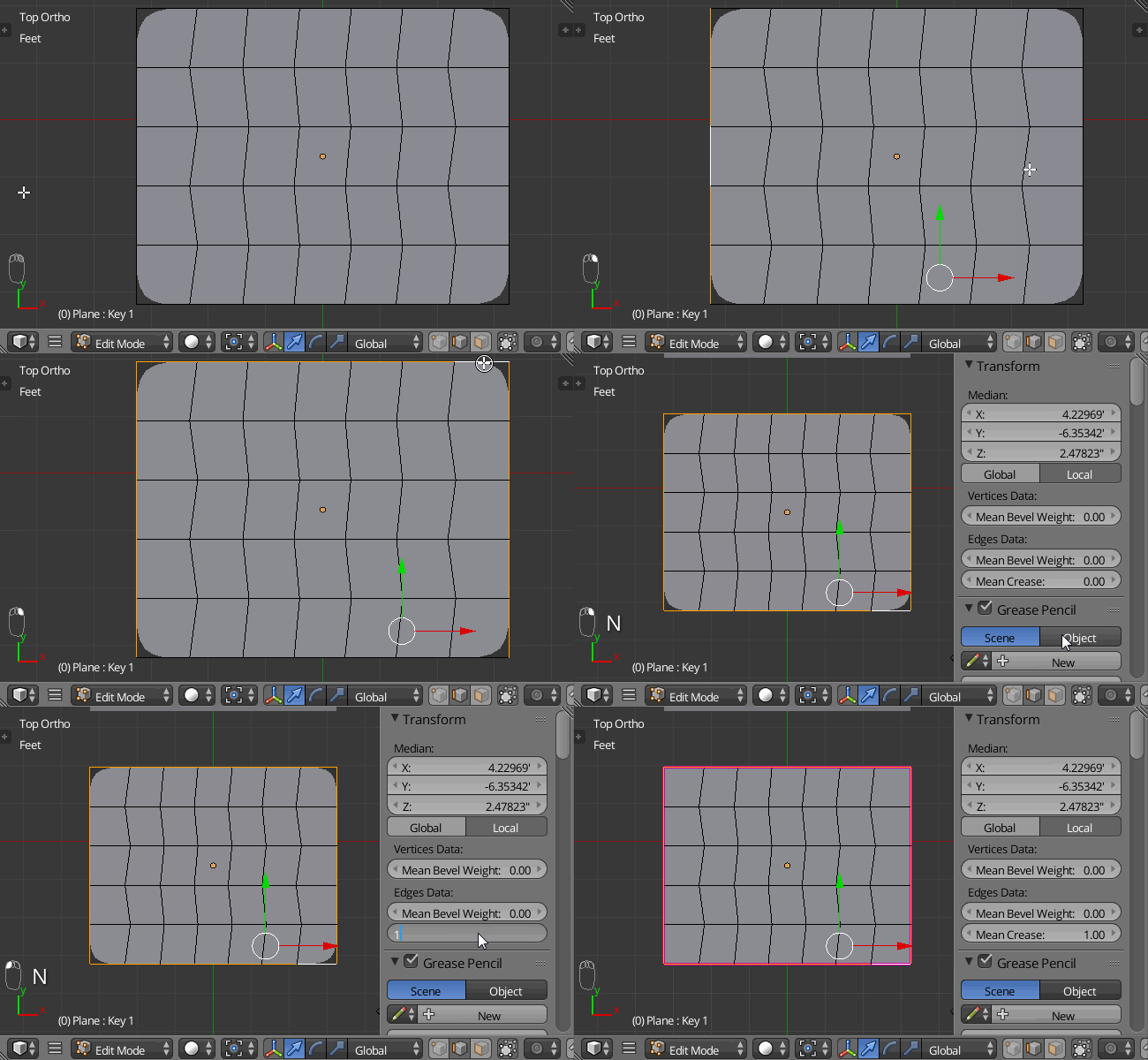
animated gif - showing part of the editing process for moving the edges 4. Add a bevel and a Subsurf modifier to the mesh. You will need to crease the outside edges, to keep the corners from rounding.
animated gif - Mean Crease

$\endgroup$
3
  • $\begingroup$ Thank you for your tip! I'm trying it now. If can I can ask an additional question - for what you mentioned in step 3, am I manually moving the edges?Is there a way to constrain the geometry so that they don't stretch or deform int he process? $\endgroup$
    – Chlyxu
    Commented Jul 17, 2016 at 2:34
  • $\begingroup$ Yes, I manually moved the edges (I did the X axis first, then the Y). It is not hard to keep the edges the same length. I will edit with more detail for step 3. $\endgroup$
    – David
    Commented Jul 17, 2016 at 2:36
  • $\begingroup$ thank you for clarifying how to keep the edge lengths, I really appreciate your input. Although, I will need to move on to manipulating and simulating a whole architectural scale screen, I'm hoping to find a method as automatic and parametric as possible so that after it is successful with a small sample, it can be applied to the real scale and scope. $\endgroup$
    – Chlyxu
    Commented Jul 17, 2016 at 23:38

You must log in to answer this question.

Not the answer you're looking for? Browse other questions tagged .