1
$\begingroup$

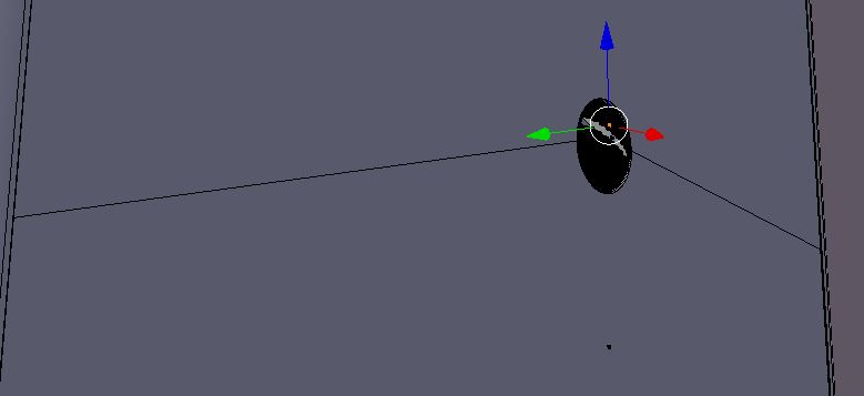
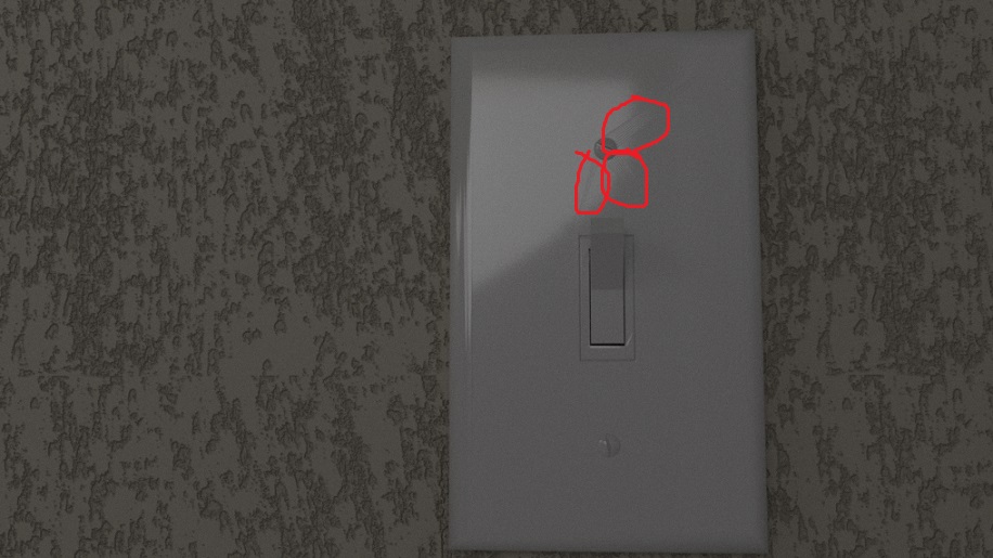
I have been working on a light switch in Blender, and it had been going well until I used the Bevel modifier to create the screws. Then, when I did a test render, this came up.enter image description here

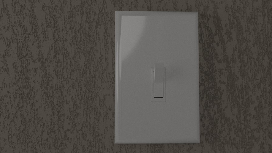
I circled my problem in red. There are unwanted streaks coming off the top screw. The previous test-render looked like this: enter image description here

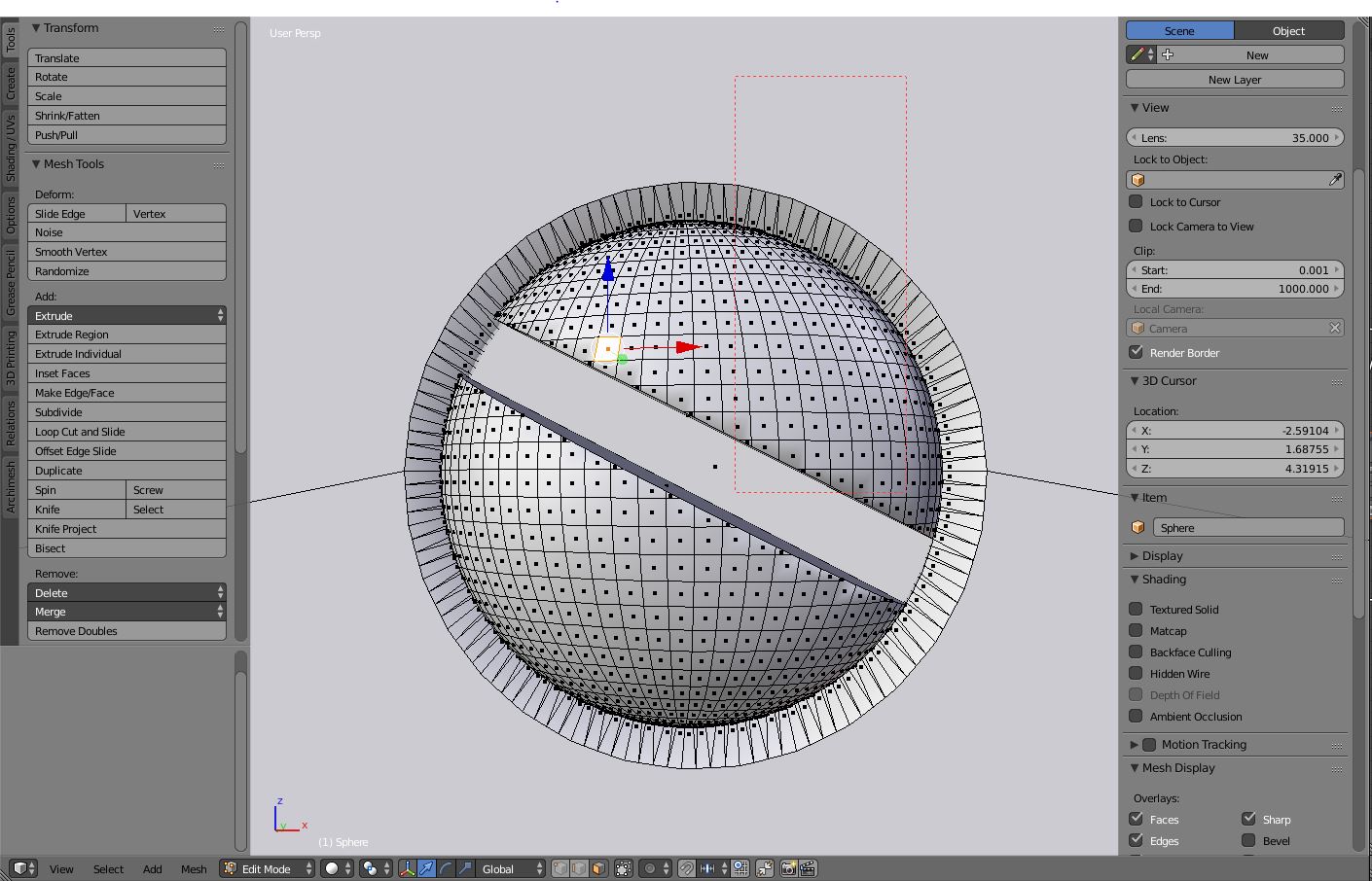
I have been working on the light-switch more and have improved it, but it continues to have those weird streaks coming off the top screw. Here are pictures of that screw in edit mode: enter image description here enter image description here

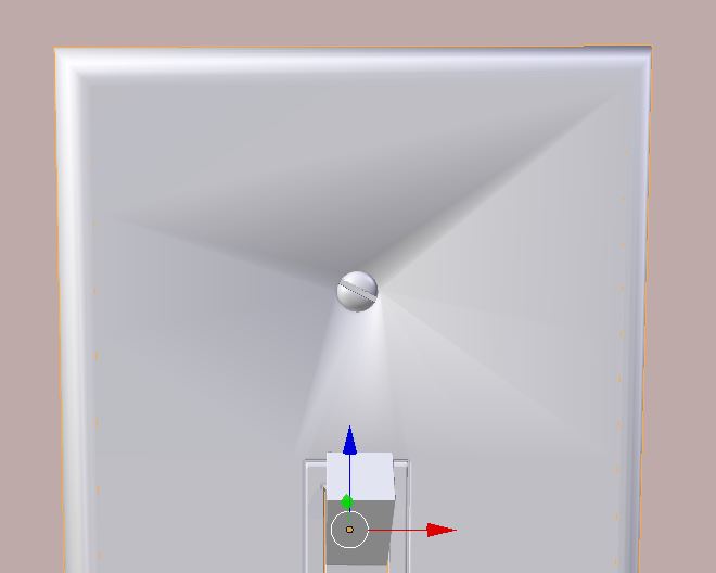
Currently I have the faces that it's happening on shaded flat. Here is a screenshot of them shaded smooth:enter image description here So, I'm thinking those lines are happening because of normals. Is that correct? and how do I correct it?

Thanks!

$\endgroup$
2
  • 2
    $\begingroup$ Do a search for non planar geometry. Also you should avoid having such large ngons on the surface of the plate. $\endgroup$
    – user1853
    Commented Nov 26, 2017 at 20:24
  • $\begingroup$ Your model has pretty bad topology, especially for something this simple. Using proper topology would probably solve half of your issues. $\endgroup$ Commented Nov 30, 2017 at 17:18

4 Answers 4

4
+50
$\begingroup$

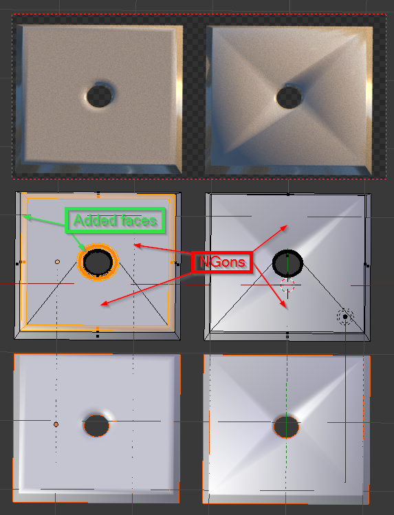
NGons (faces with more than 4 vertices/edges) are very simple and useful on flat surfaces but usually give nothing good on smooth curved surfaces. Knowing and using good topology is the key but when it's too late, you can make your mesh look better using good topology around your NGons.

In edit mode, select your NGons select

Hit I to activate inset and use the mouse to control the distance inset

Click the Mouse when it's ok.

This will make your NGon surrounded with, hopefuly, good flat topology and reduce the artifacts. render view

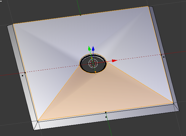
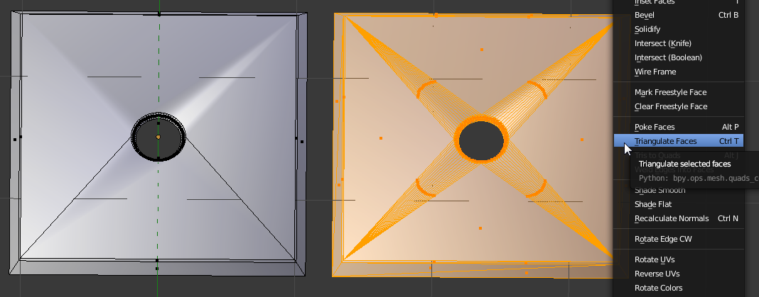
Remember than an NGon is not really a single face, it looks like a single face to make it easy to use, manipulate and see but it you want to know what it is really, select your mesh in edit mode and ust CTRL+T or CTRL+F (face menu) and triangulate faces. You'll see something lake this : ngon triangulated

All triangles from the center linked to the 4 vertices in the corners making really bad poles. Smooth surfaces have to be quads (faces made with 4 vertices/edges), with mostly poles of 4 edges (sometimes 3, sometimes 5 but as few as possible, controlling the edge flow).

$\endgroup$
7
$\begingroup$

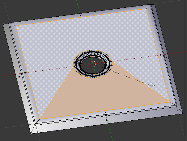
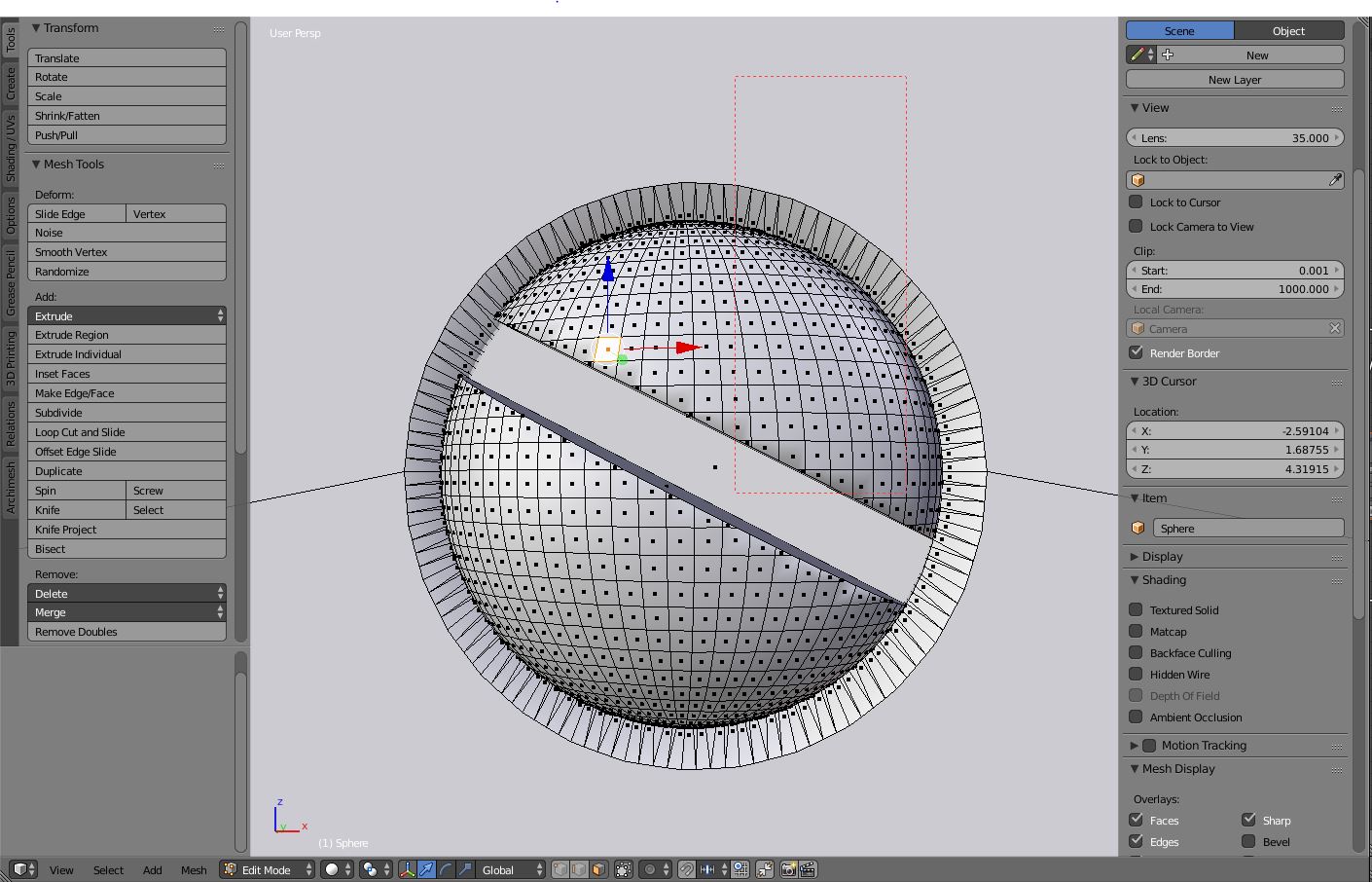
The problem is your statement that the render is showing "geometry that isn't there." It is...see this image?
enter image description here

All of those edges around the circumference of the screw hole are edges, so your polygon for the plate has like 72 edges. Blender is trying to figure out the normals for a 72-edge polygon, but it's getting confused. Just because Blender let you add that sphere doesn't mean that it's a good idea. For fun, try selecting the faces of just the plate, and choose Mesh->Faces->Triangulate Faces. I bet you'll get a ton of triangles on what you think is a simple flat polygon, like this:
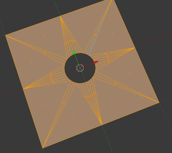
enter image description here

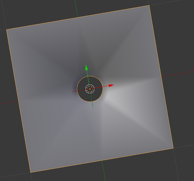
And then with smooth shading turned on, you might get something like this:
enter image description here

That's a perfectly flat plane (with a hole in the middle), but Blender's trying to figure out how to smoothly shade those triangles.

The best solution is to separate the screw from the plate, and make the two into separate models. See @Dontwalk's solution above for a way to model just the plate part with a nice hole.

In general, there is no good reason to model the screw and the plate as a single mesh. If you want them to be together, you can group them. By modeling them together as a single mesh you're making the topology of the plate way more complicated than it has to be.

Hope this is helpful!

As a side note, the screw head is not well-modeled either. It looks like you took a sphere and just cut the slot right across it at the angle you wanted, making some of the quads into triangles and turning the quads into trapezoids. You could have modeled the slot straight across so that it followed the quads, and then rotated the head, and that would have given you a much cleaner model (of the screw head).
$\endgroup$
4
$\begingroup$

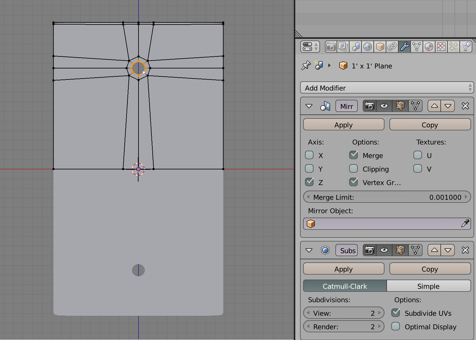
Try an approach like this. I didnt take the time to complete the model. I can if you need me too. enter image description here

$\endgroup$
1
$\begingroup$

Probably a side effect of the following combination :
- used Bevel
- used subdivision modifier
- used smooth surface.

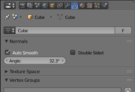
Although one might use the edge-split modifier to solve it, that's often not ideal. As it simply cuts flat surfaces. A much nicer solution is to use auto smooth on the vertex of the cube as shown below, combine this width a Bevel option of 3 segments, and it should look good.

enter image description here

$\endgroup$

You must log in to answer this question.

Not the answer you're looking for? Browse other questions tagged .