7
$\begingroup$

I'm trying to figure out how to twist a procedural material applied to a mesh.

I have a hollow cylinder like a tube (the two end cap faces are deleted) with a noise texture applied to it.

My nodes are:

  1. Texture Coordinate - Generated output to a Mapping Node, Vector input.
  2. Mapping Node - Vector output to Noise Texture, Vector input.

On the mapping node, I can see that the Rotation ordinates will rotate the texture on the surface of the cylinder. The length of my cylinder runs down the Y axis, so as I rotate the texture on the Y axis it rotates around the barrel of the cylinder. So far so good, but the problem is that it equally rotates the texture around the cylinder barrel all along its entire length.

What I want to do is to fix the material's rotation on one end of the cylinder, but rotate it around other end so that it twists or spirals down the length of the cylinder like the rifling in a gun barrel.

Is there a way to tell Blender "on that end of the cylinder the material's rotation is 0, and on this end it is 360 degrees (or 720, or -180, or whatever)?

This seems as if it'd be a piece of cake, but I'm just not seeing it.

$\endgroup$
1
  • 1
    $\begingroup$ Are you using the texture node editor. If yes you can add a rotation node and plug in a gradient texture node. Otherwise if you're just using procedural textures within cycles I don't know of any answers. $\endgroup$
    – Nils Eisen
    Commented Apr 24, 2017 at 2:28

2 Answers 2

12
$\begingroup$

While @DuateFarrajotaRamos's answer will seem to work for small angles of rotation, it only approximates rotation and will not achieve 360 degree rotation mentioned in the question. Instead, you can apply a rotation matrix to the actual vectors concerned.

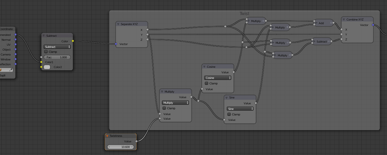
A solution is mentioned as part of this answer https://blender.stackexchange.com/a/77638/29586 - where the X/Z coordinates are rotated based on the Y coordinate using the following nodes :

rotation

This works by splitting the Vector into separate X,Y,Z coordinates and applying a rotation using matrix multiplication as :

X = x.cos(angle) + z.sin(angle)
Z = -x.sin(angle) + z.cos(angle)

Varying the Twistiness input will vary the rotation. The Twistiness is measured in Radians rather than degrees so 2*pi radians is a full rotation (360 degrees) - just type '2*pi' into the value node and Blender will automatically calculate.

Note also the Subtract color mix node at the start. This is set to mid-grey (0.5,0.5,0.5) to convert the Generated coordinates ranging from 0.0 to 1.0 into the range -0.5 to 0.5 so that the origin - and centre of rotation - is in the centre of the mesh.

For clarity, here's the complete node setup :

full material

Note that I've removed the 'green' element from the first Subtract MixRGB node. This is to leave the origin of the Y channel at the edge of the mesh so that one end is not affected by the twist (otherwise it twists from the middle). The Subtract and Divide nodes at the end (after the Noise texture) are there simply to increase the contrast of the Noise texture and isn't related to the twisting.

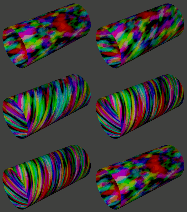
And here's the result :

animated result

Blend file attached

$\endgroup$
5
  • $\begingroup$ Ah yes good point, Rotation matrix are something I've always wandered how to do, but my limited math knowledge did not allow. I'll use this for future reference, upvoted, thanks. $\endgroup$ Commented Apr 24, 2017 at 13:19
  • $\begingroup$ Ok, this looks fascinating, and I can't wait to give this a shot, and now I want to build the abstract EM waves from the other post too. I can see that you're using the converter and math nodes to build the rotation equations. Where I'm hitting a brick wall is the node titled "Twistiness." I don't find it anywhere. Is it a custom node, or a group of nodes that you saved out? The Attribute input can access something called "Pointiness," (also on the Geometry input) but I don't find your node anywhere. Any hints? $\endgroup$ Commented Apr 24, 2017 at 20:44
  • $\begingroup$ Sorry for the confusion and lack of explanation. It's an Input Value node which has been renamed to Twistiness via the properties panel - it is confusing when the heading changes. I'll upload a Blend file with it already set up so that you can play around with a working version. $\endgroup$ Commented Apr 24, 2017 at 21:04
  • $\begingroup$ @Jendulus_Blendulus Answer updated with a complete material - without renamed nodes. Hopefully it's clearer. Also included animated example of the twisting in action and Blend file. $\endgroup$ Commented Apr 24, 2017 at 23:00
  • 1
    $\begingroup$ Thanks hugely. This completely did the trick with maximum flexibility. Being able to just type in different multiples of pi into the Input Value (twistiness) node is so perfect! This absolutely nailed it. I can't thank you enough! $\endgroup$ Commented Apr 25, 2017 at 1:00
6
$\begingroup$

As mentioned by Nils you can do this by mixing two different texture coordinates.

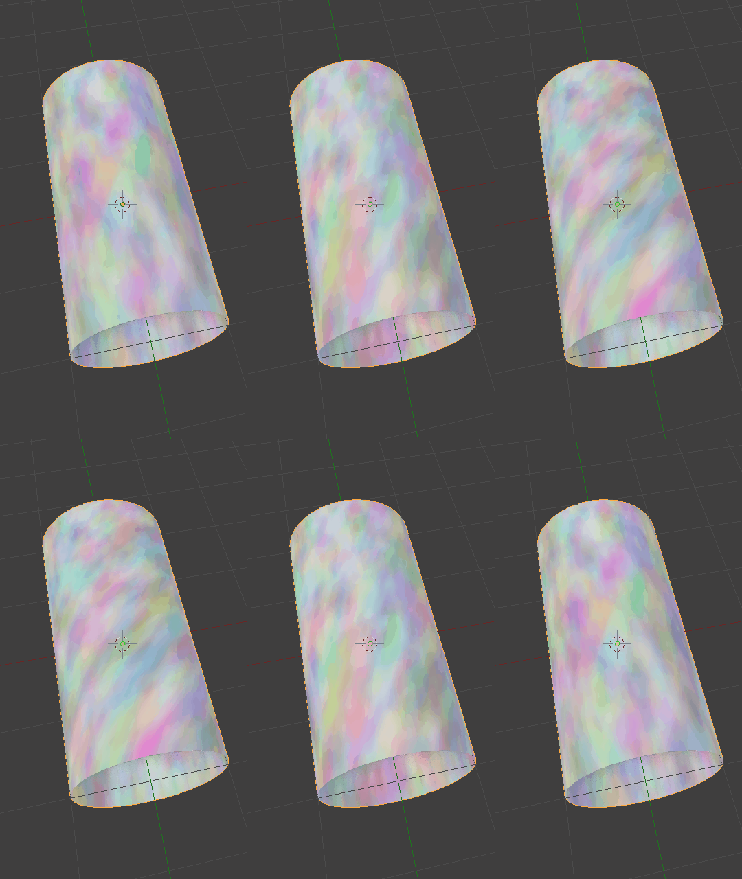
Twisting

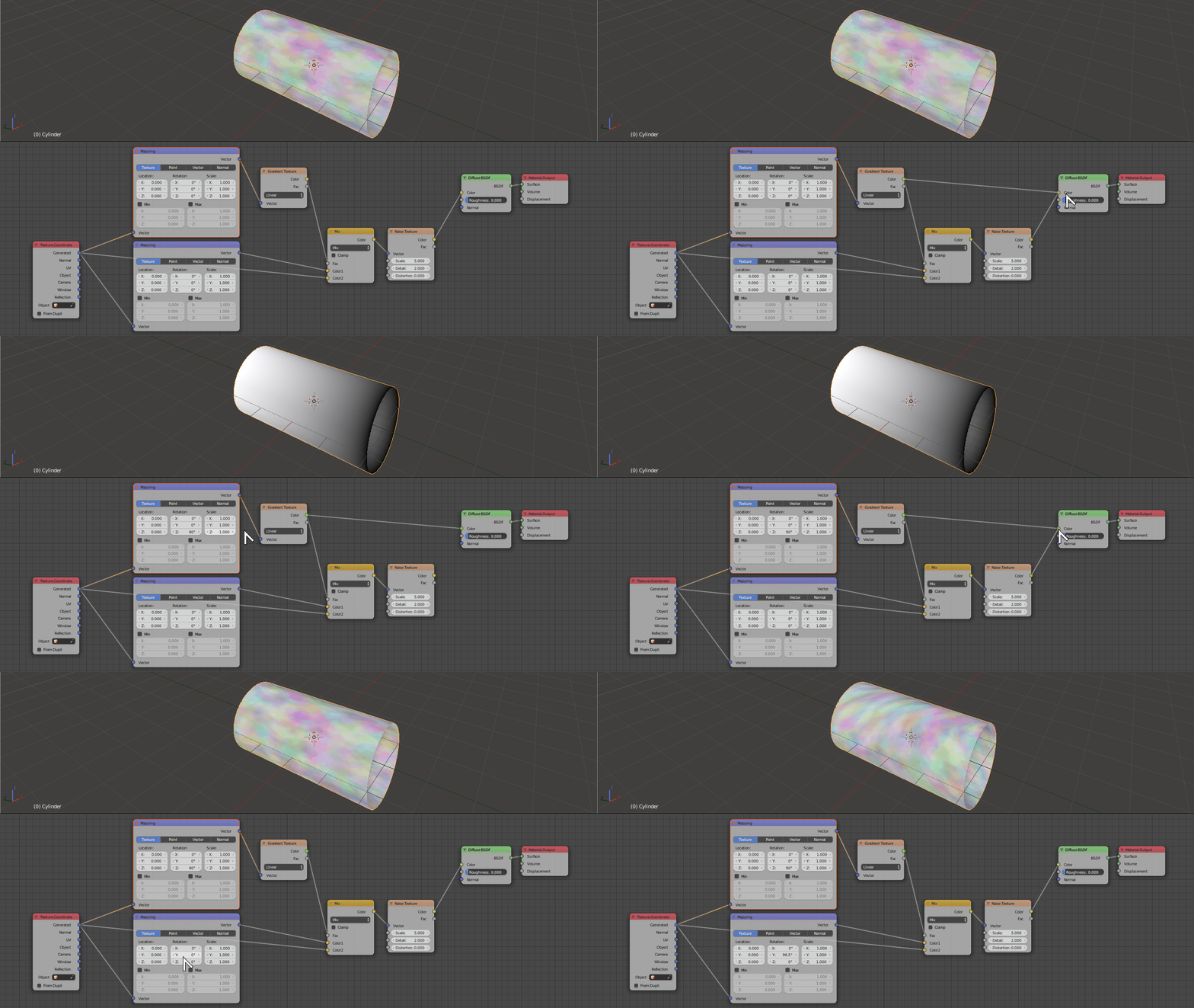
There is no direct built-in way to "mix" texture coordinates in Cycles nodes, but since the three XYZ axis are essentially like the three RGB components, and cycles makes no intrinsic distinction between the two data formats, you can use a Color Mix node to combine different texture coordinates.

The advantage of this is you can also use a texture to mix them differently across an object surface.

So if you create a black and white gradient across your cylinder's Y axis you can use it to mix between rotated and non-rotated texture coordinates.

Just plug the original Generated texture coordinates to one of the Color sockets of a Color Mix node and the same Generated texture coordinates run through a Vector Mapping node to the second Color Socket.

Use the gradient texture to mix the two, then control rotation through the Vector Mapping node.

Twisting

$\endgroup$
1
  • 1
    $\begingroup$ I believe this will only work for small angles. For the 360 degree rotation you'll need to apply a rotation directly to the coordinates rather than using the Mix node. The mix node will produce distortion - see the back inside face on your animated example. $\endgroup$ Commented Apr 24, 2017 at 9:03

You must log in to answer this question.

Not the answer you're looking for? Browse other questions tagged .