Emulate light scattering using a volumetric emission shader
Using Volumetric scatter produces the most accurate results but required a considerable number of render samples to get satisfactory results. A much more efficient alternative is to fake the light scattering using an Emission volumetric shader.
Create an image of the light emission - black where there is no emission and brighter where light is emitted. For example, to mimic the Windows logo you could start with an image as follows :
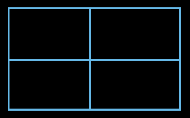
You can use the Surface of a mesh to render the image of the 'window' and the volume for the rays and the shader will use the Object coordinates. It's helpful to move the Origin of the mesh to a point on the surface and to use a Mapping node to re-orient the coordinates to something more intuitive. In my case, I've used the default Cube, moved the origin to the centre of the face crossing the -Y axis and rotated the coordinate space so that X/Y is along the axes of the window and Z represents the distance from the window.
To achieve this, start with the default cube, open the Properties panel (N) and move the 3D cursor to 0,-1,0. open the Tools panel (T) and Set Origin to 3D Cursor.
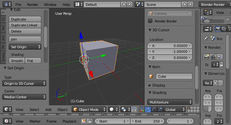
Assign a material and add the following nodes :
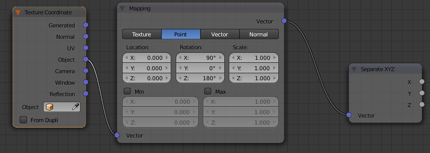
This arrangement remaps the X, Y, Z coordinates so that the XY plane maps to the 'back' of the cube and the Z coordinate represents the distance from the 'back'. In this way we can easily map our Texture coordinates (XY) and use Z to represent the depth. The re-mapping of the origin ensures that 0 depth (Z) represents the 'back' face of the mesh.
Using an Emission Shader to add the Image texture will result in the image being rendered on both the 'back' and 'front' surfaces of the mesh. To 'hide' the front face we can use the Z coordinate to set Strength to zero whenever Z is greater than a constant and adding in a Transparent shader makes the mesh transparent (Note : I've set the Transparent shader to be less than 100% White so that it shows in this image - normally this would want to be 100% transparent so the mesh is not visible.)
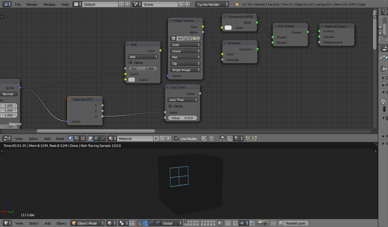
To add the rays we can start by simply adding another Emission shader driven from the same image and connected to Volume Material Output socket rather than Surface. This will produce parallel rays :
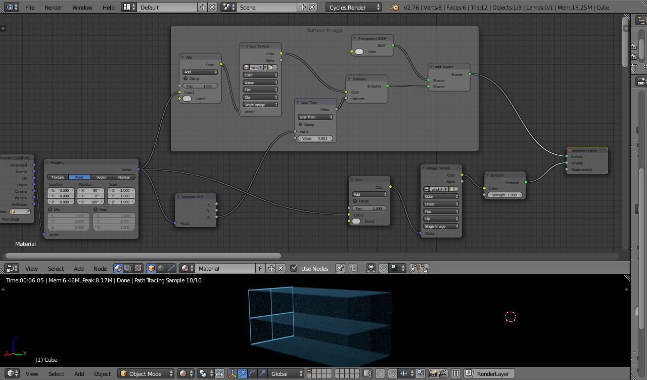
NOTE : The MixRGB Add nodes translate the coordinates so that the textures are centred around 0,0 rather than the texture origin falling at the bottom-left of the image.
To get the rays to diverge you can scale them using the Z coordinate - the scale should be '1' at the 'back' surface and increase as Z increases.

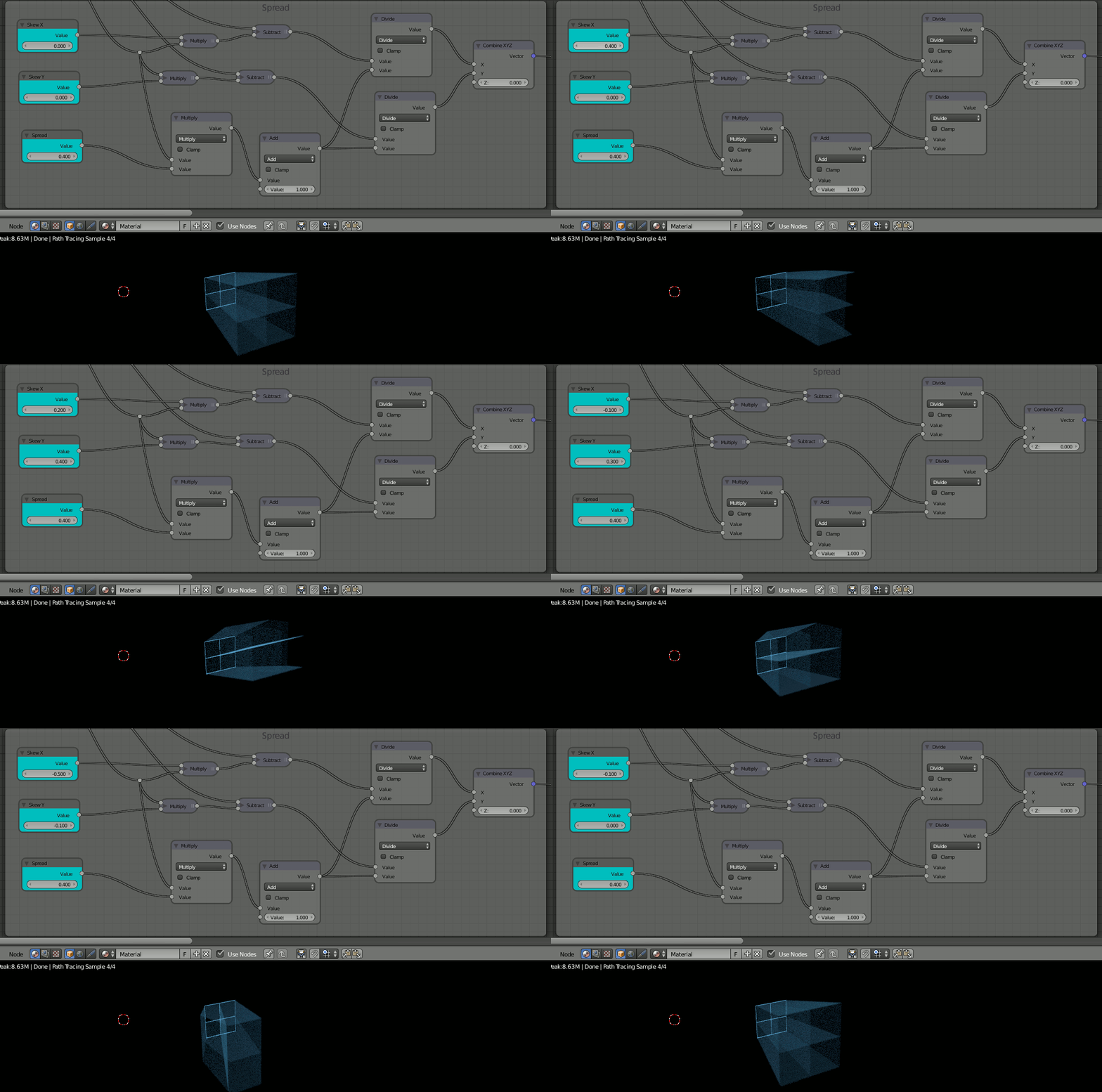
It may be useful to be able to control the direction of the rays and a similar technique can be used to add offsets (also based on Z) to Skew the rays as they travel through the volume.
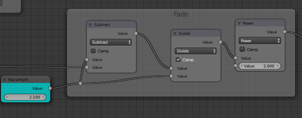
The rays should fade along their length. For this we can simply vary the strength based on the Z coordinate :
We also might want them to spread out as they travel. Again, the Z coordinate can be used - this time controlling the effect of a high frequency Noise texture to scatter the rays :

Finally, we can add some variation to make the rays less uniform.

Bringing it all together produces the following material :

Tweaking the source image and varying the Z-coordinate of the noise used for the rays and adding a Fog Glow in the compositor can produce the following :

Of course, you aren't just limited to single-colour source images :
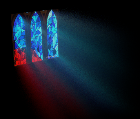
Blend file attached. 


