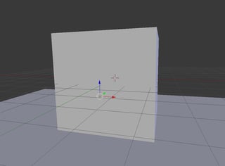
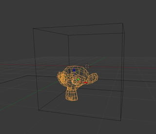
Here is the result of my mathematical approach:

And the nodes for the outer object:

The value nodes on the far left are driven by the positions of the target (inner) object (top three) and camera (bottom three).
And here are the contents of the Norm node group, which returns the norm (i.e. magnitude) of the input vector:

The basic idea of my approach is to take the ray vector (from the camera to the sampled point on the mesh) and extend it to the inner object, then test how far this extended ray vector is away from the center of the inner object and use that information to adjust the outer object accordingly. (In my example I reduced the IOR and made the glass lighter to make the inner object more visible.)
See below for a more thorough look at the math.
The only downside here is that the "hole" in the outer mesh will not be the exact shape of the inner object since I am basically approximating the inner object to be a sphere.
And here's the .blend:

The Math
Note, this answer is already fairly long and defining all the mathematical terms and concepts I am using here would make it much longer. So to understand this section you should have decent precalculus grasp of vector math. If you don't understand this part fully you can still just copy my nodes, or feel free to open a chat room with me and I would be more than happy to explain whatever you want.
- Call the camera's position $\vec{C} = (Cx,Cy,Cz)$.
- Call the center of the target (inner) object $\vec{T} = (Tx,Ty,Tz)$.
- Call the sampled point on the outer object $\vec{P} = (Px,Py,Pz)$.
- Call the radius of the inner object $R$.
- The vector of the incoming ray is $\vec{CP}$, for simplicity I will call it $\vec{r}$.

The idea now is to determine if $\vec{r}$ is aiming towards the inner object. To do this, normalize $\vec{r}$ and multiply it by the norm of $\vec{CT}$. This will result in a new vector $\vec{r}^{\,\prime}$ in the same direction as $\vec{r}$ and length as $\vec{CT}$.

The last step is to determine if $\vec{r}^{\,\prime}$ intersects the inner object. This is pretty simple, just take the difference $\vec{r}^{\,\prime}-\vec{CT}$ to make a new vector $\vec{D}$.

This gives the final formula for the distance to compare to $R$:
$$
\left\vert\left\vert \vec{D} \right\vert\right\vert = \left\vert\left\vert \frac{\vec{r}}{\left\vert\left\vert \vec{r} \right\vert\right\vert} - \vec{CT} \right\vert\right\vert
$$
The node layout is just this formula, then sent through an RGB Curves node to tweak the falloff (the Add node right after the RGB Curves adds 0, it's purpose is to clamp the value to $[0,1]$), then used to mix the two glass shaders. The Less Than math node at the very bottom compares the norms of $\vec{CT}$ and $\vec{r}$ (not $\vec{r}^{\,\prime}$) to apply the effect only in front of the target object.
Ping me in chat if you have any questions about the nodes or the math, I'm happy to explain further there if needed!


