5
$\begingroup$

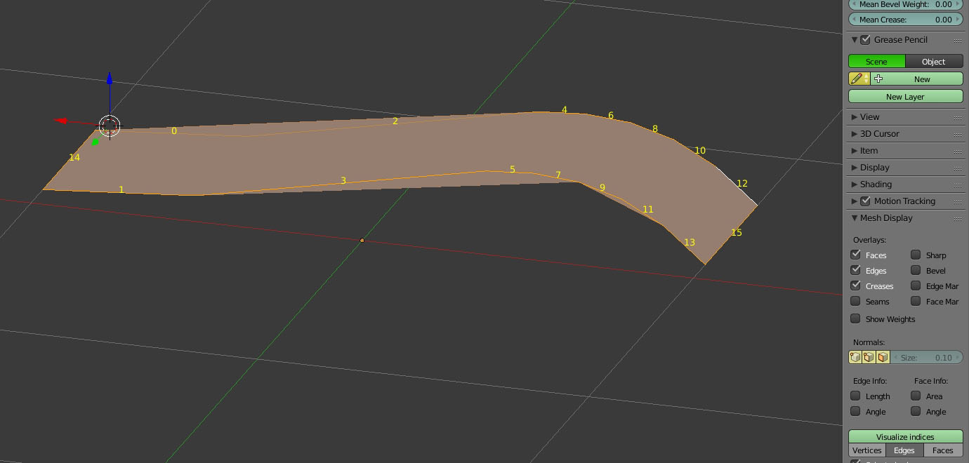
I try to create a face between two edges, but it always gets a strange looking result.
I worked for years with another cad application called "Vector". In this App if you select edges, the software orders the edges from 0 to n by selection and shows the order. Blender doesn't do this, but I found an extension called "space_view3d_index_visualiser_bmesh.py", no it works fine.

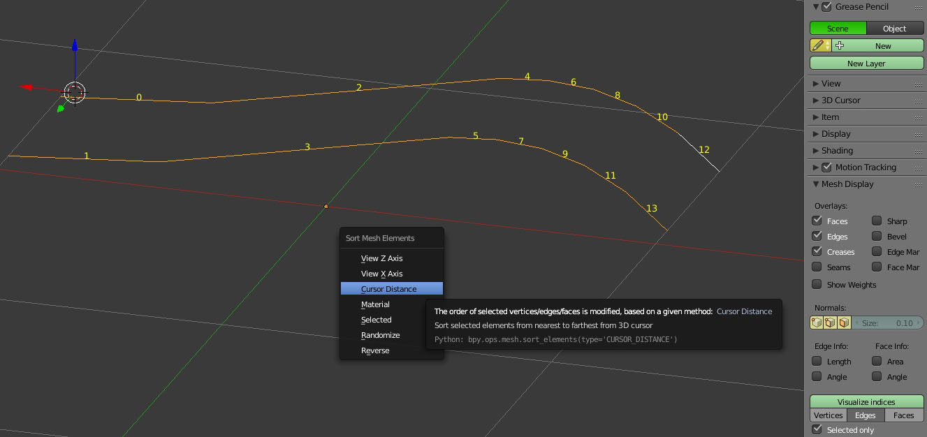
The internal blender order seems quite confused, so I reordered it with "Sort Mesh Elements".

new order works

After pressing F to create a face between the edges, this is the result:

strange face after "f"

I think this is an edge order problem. If I Select each corresponding edge separately (0-1, F, 2-3 F .... etc) it works fine, but this is boring work with large Objects. Is there any solution?

$\endgroup$
1
  • $\begingroup$ ctrl+E then "bridge edge loops" (before you create the face) $\endgroup$
    – lemon
    Commented Aug 8, 2016 at 15:56

3 Answers 3

7
$\begingroup$

F in blender creates one face. So when you have many edges selected at once you are creating one large Ngon, not what you want to do.

You are looking for blender's bridge edge loops tool. In edit mode from the 3D view header Mesh > Edges > Bridge Edge Loops. Or quicker through keyboard shortcuts CtrlE L.

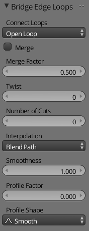
After running the bridge edge loops tool you will get more options in the operator part of the tool shelf.
bridge edge loops settings

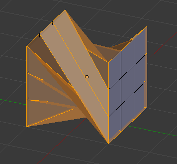
One of the most important is the Twist, if you get edges that are crossing over each other like in the image below, then just change the number till the offset is correct. bridge error

$\endgroup$
4
$\begingroup$

The simplest solution for you would to just use the F key. Blender will automatically bridge the edges if you first select the first two vertices of the edges and press F. This will just create a line in between the vertices. But if you keep pressing F, Blender will automatically detect which edges to fill next. Blender does the hard work for you.

$\endgroup$
2
$\begingroup$

Because CAD system use different approach to modeling. It's like "curve"s vs "mesh" in Blender or "splines" vs "mesh" in 3Ds.

For cases like this usually work "Grid fill".

In edit mode press: "CTRL + F" > "G"

You can adjust properties in Tool panel on left.

BTW: does not matter on vertex order.

$\endgroup$

You must log in to answer this question.

Not the answer you're looking for? Browse other questions tagged .