1
$\begingroup$

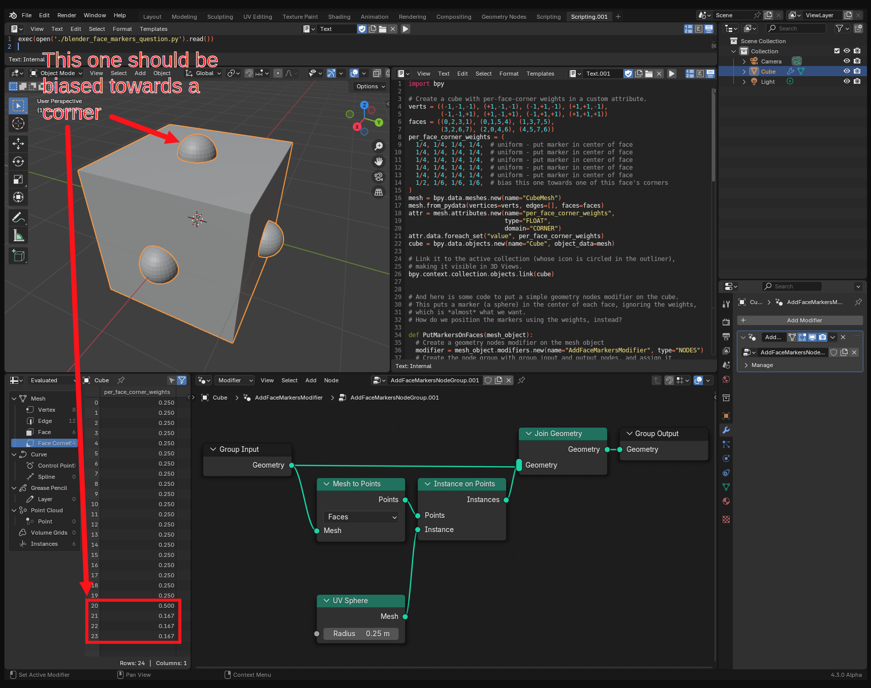
I'd like to use geometry nodes to put a marker on each face of a mesh. Each marker should be placed at specified weighted average of that face's vertices, and should stay at that weighted average as the mesh is transformed and deformed without changing structure. The desired weights have been precomputed and placed into a per-face-corner attribute on the mesh.

How can I accomplish this?

I see there are some geometry node types that might be relevant: "Corners of Face", "Capture Attribute", but I haven't figured out how to string them together yet.

The script included below sets up a toy case: a cube, with the per-face-corner weights in an attribute called "per_face_corner_weights". These weights specify that all the markers should appear in the centers of the faces, except for the one on the top face, which should be biased towards one corner.

This script also puts a simple geometry nodes modifier on the cube, which just puts a marker at each face center (ignoring the weights).

How can I position each marker using the per-face-corner weights, instead?

screenshot of script showing marker in center of each face

import bpy

# Create a cube with per-face-corner weights in a custom attribute.
verts = ((-1,-1,-1), (+1,-1,-1), (-1,+1,-1), (+1,+1,-1),
         (-1,-1,+1), (+1,-1,+1), (-1,+1,+1), (+1,+1,+1))
faces = ((0,2,3,1), (0,1,5,4), (1,3,7,5),
         (3,2,6,7), (2,0,4,6), (4,5,7,6))
per_face_corner_weights = (
  1/4, 1/4, 1/4, 1/4,  # uniform - put marker in center of face
  1/4, 1/4, 1/4, 1/4,  # uniform - put marker in center of face
  1/4, 1/4, 1/4, 1/4,  # uniform - put marker in center of face
  1/4, 1/4, 1/4, 1/4,  # uniform - put marker in center of face
  1/4, 1/4, 1/4, 1/4,  # uniform - put marker in center of face
  1/2, 1/6, 1/6, 1/6,  # bias this one towards one of this face's corners
)
mesh = bpy.data.meshes.new(name="CubeMesh")
mesh.from_pydata(vertices=verts, edges=[], faces=faces)
attr = mesh.attributes.new(name="per_face_corner_weights",
                           type="FLOAT",
                           domain="CORNER")
attr.data.foreach_set("value", per_face_corner_weights)
cube = bpy.data.objects.new(name="Cube", object_data=mesh)

# Link it to the active collection (whose icon is circled in the outliner),
# making it visible in 3D Views.
bpy.context.collection.objects.link(cube)


# And here is some code to put a simple geometry nodes modifier on the cube.
# This puts a marker (a sphere) in the center of each face, ignoring the weights,
# which is *almost* what we want.
# How do we position the markers using the weights, instead?

def PutMarkersOnFaces(mesh_object):
  # Create a geometry nodes modifier on the mesh object
  modifier = mesh_object.modifiers.new(name="AddFaceMarkersModifier", type="NODES")
  # Create the node group with group input and output nodes, and assign it
  # to the modifier (like bpy.ops.node.new_geometry_node_group_assign() does)
  node_group = bpy.data.node_groups.new(name="AddFaceMarkersNodeGroup", type="GeometryNodeTree")
  node_group.interface.new_socket(name="Geometry", in_out="INPUT", socket_type="NodeSocketGeometry")
  node_group.interface.new_socket(name="Geometry", in_out="OUTPUT", socket_type="NodeSocketGeometry")
  modifier.node_group = node_group
  nodes = node_group.nodes
  group_input_node = nodes.new(type="NodeGroupInput")
  group_output_node = nodes.new(type="NodeGroupOutput")
  # Add my nodes
  mesh_to_points_node = nodes.new(type="GeometryNodeMeshToPoints")
  mesh_to_points_node.mode = "FACES"  # change from "VERTICES"
  uv_sphere_node = nodes.new(type="GeometryNodeMeshUVSphere")
  uv_sphere_node.inputs['Radius'].default_value = 0.25  # change from 1
  instance_on_points_node = nodes.new(type="GeometryNodeInstanceOnPoints")
  join_geometry_node = nodes.new(type="GeometryNodeJoinGeometry")
  # Add connections between nodes
  links = node_group.links
  links.new(group_input_node.outputs['Geometry'], join_geometry_node.inputs['Geometry'])
  links.new(join_geometry_node.outputs['Geometry'], group_output_node.inputs['Geometry'])
  links.new(group_input_node.outputs['Geometry'], mesh_to_points_node.inputs['Mesh'])
  links.new(mesh_to_points_node.outputs['Points'], instance_on_points_node.inputs['Points'])
  links.new(uv_sphere_node.outputs['Mesh'], instance_on_points_node.inputs['Instance'])
  links.new(instance_on_points_node.outputs['Instances'], join_geometry_node.inputs['Geometry'])
  # Set node locations for the geometry nodes editor
  group_input_node.location.x = -500.0
  group_input_node.location.y = -25.0
  group_output_node.location.x = 160.0
  group_output_node.location.y = 0.0
  mesh_to_points_node.location.x = -320.0
  mesh_to_points_node.location.y = -80.0
  uv_sphere_node.location.x = -320.0
  uv_sphere_node.location.y = -265.0
  instance_on_points_node.location.x = -160.0
  instance_on_points_node.location.y = -80.0
  join_geometry_node.location.x = 0.0
  join_geometry_node.location.y = 0.0
  # Hide unconnected inputs on all nodes (like ctrl-h which toggles them in ui)
  for node in node_group.nodes:
    for input in node.inputs: input.hide = True  # gets rejected if connected; good
    for output in node.outputs: output.hide = True  # gets rejected if connected; good
  # Then unhide interesting unconnected inputs (ones we've set default values on)
  uv_sphere_node.inputs["Radius"].hide = False
  # Deselect all the nodes
  for node in node_group.nodes: node.select = False

PutMarkersOnFaces(cube)

# Make the cube selected and active (mainly so its geom nodes modifier
# will appear in the geometry nodes editor)
cube.select_set(True)
bpy.context.view_layer.objects.active = cube
$\endgroup$

1 Answer 1

1
$\begingroup$

I came up with something that works. At this point this feels uncomfortably like dog science ("I have no idea what I'm doing").

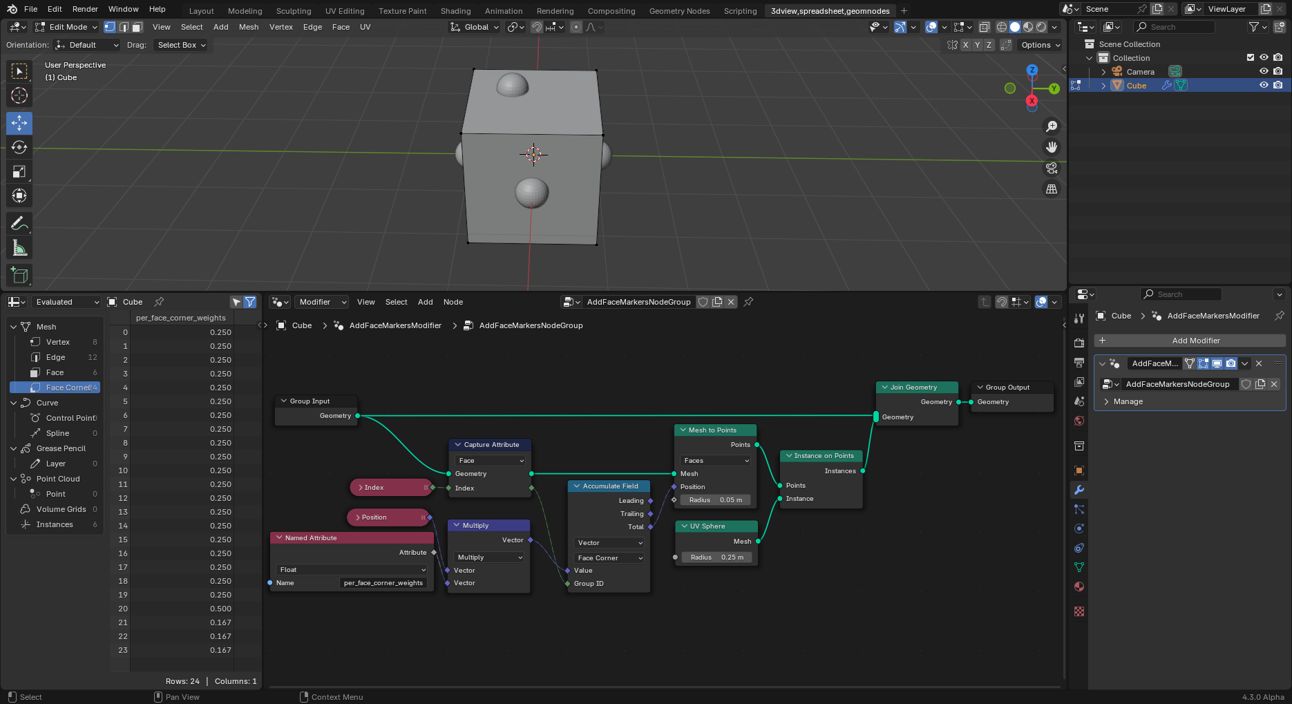
I think the idea is sound: multiply together the position and weights attributes to get a product per-face-corner attribute; then use an "Accumulate Field" node to aggregate (sum) the result by face index, which turns the per-face-corner attribute into per-face attribute of marker positions, and then use "Mesh to Points" and "Instance on Points" with "UV Sphere" as the instance, to put sphere instances at the resulting per-face positions.

But honestly I don't understand the graph I created. I think I'm probably taking advantage of some automagical conversions that I don't understand-- in particular, I'm combining positions and per_face_corner_weights, which are in two different domains, and that part of the graph seems pretty far away from anything that even knows what the domains are, so I'm really surprised it all works. [EDIT: I understand this now; it has to do with the fact that the specification of the domain of evaluation flows from right to left in the graph. Solution #3 calls this out and discusses it more, in the text and in the node graph labels.]

blender session with solution geom node graph and resulting in 3d view


EDIT: Solution #2

Here's an alternative solution, a bit cleaner, I think.

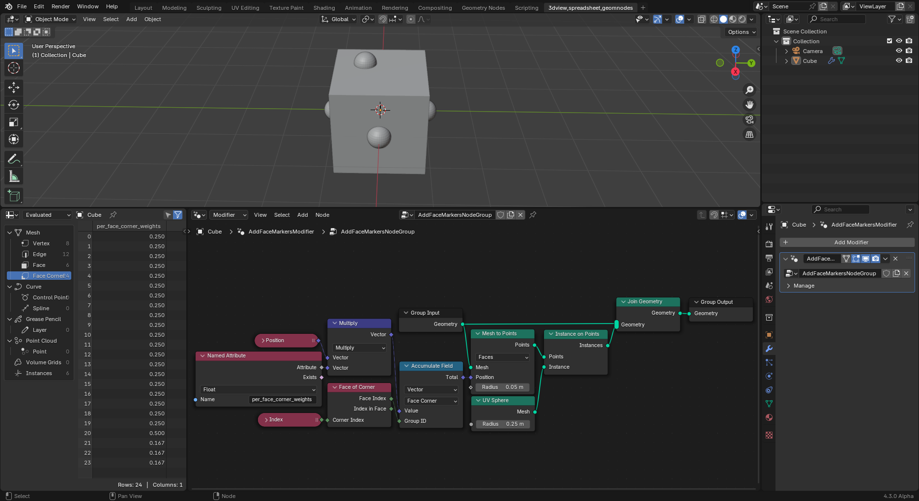
The difference from the previous solution is the part that coerces the domain of the "Index" node to be face instead of face-corner, before feeding it into the "Group ID" input. The previous solution accomplished that by using "Index"->"Capture Attribute (domain=Face)". This solution uses "Index"->"Face of Corner" instead. So this part no longer requires a geometry, resulting in fewer edges overall which means less stuff I don't understand, which seems like a good thing.

blender session of second solution


EDIT: Solution #3

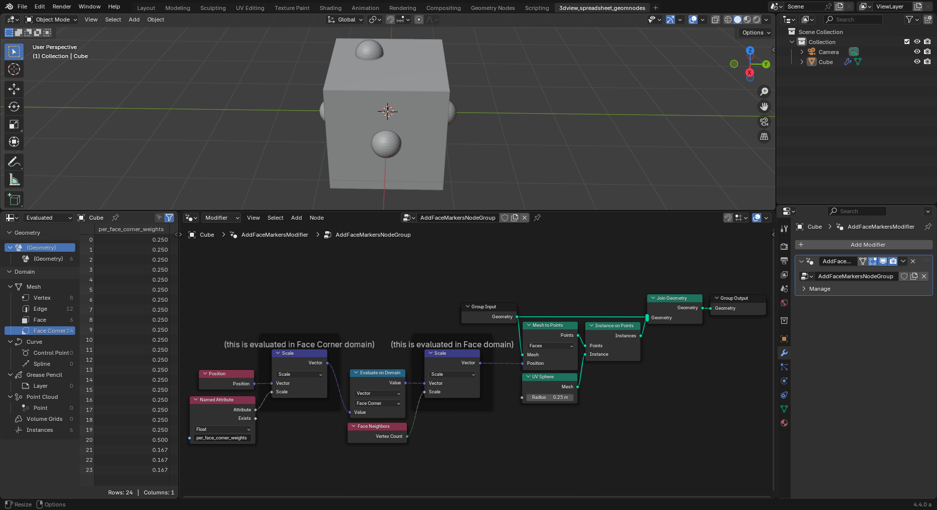
This incorporates a suggestion by Markus von Broady in the comments: instead of using the "Accumulate Field" node, just multiply the vertex positions by the weights in the Face Corner domain, and then let the result be implicitly converted (by averaging) when evaluating in the Face domain, then correct the average to sum by multiplying by number of vertices per face.

Detail: The "Evaluate on domain (Face Corner)" node is necessary to force the multiplication to be done in the Face Corner domain, rather than the Face domain. At first I thought that must be followed by a "Evaluate on domain (Face)" node to force conversion (averaging) into the Face domain, but it turns out that's not necessary, since the domain of evaluation of a field op is always what is mentioned to its right, never to its left.

blender session of third solution

$\endgroup$
9
  • $\begingroup$ You don't need "Accumulate Field". You can multiply each corner by the weight, and capture that. Then you can read captured attribute on the face domain - the interpolation will average all corners. Now multiply that by the number of corners ("Corners of face: Total") and you're good to go. Similar logic to here $\endgroup$ Commented Nov 12 at 22:02
  • $\begingroup$ @MarkusvonBroady Thank you!! I will try that. $\endgroup$
    – Don Hatch
    Commented Nov 12 at 22:06
  • $\begingroup$ @MarkusvonBroady When you say "and capture that", do you mean using a "Capture Attribute" node? Which means I would have to thread the Geometry through that? That seems like it might be a step backwards in a sense, no? I notice in the first picture in your linked answer, there are no Geometries in sight, which seems like a good thing-- looks like you are using an "Evaluate on Domain" node for roughly the same purpose? I am trying that-- it doesn't work with a single "EoD (domain=Face)" for some reason, but it seems to work if I use two EoD's chained: domain=Face Corner, then domain=Face. $\endgroup$
    – Don Hatch
    Commented Nov 12 at 23:23
  • $\begingroup$ @MarkusvonBroady Here is a screenshot of the two-chained-"Evaluate on Domain"-nodes that seems to work. Does this seem reasonable? i.sstatic.net/0bmiYcIC.png (Also I'm using "Face Neighbors: Vertex Count" instead of your suggested "Corners of face: Total", looks like it's equivalent and maybe a bit easier to understand at a glance) $\endgroup$
    – Don Hatch
    Commented Nov 12 at 23:27
  • 1
    $\begingroup$ After more experimenting, I think I have come to the conclusion that the "EoD (domain=Face)" is a no-op and can be safely omitted; the "Scale" by face vertex count will be done in the Face domain regardless. This because (I think) the domain of evaluation of a field op is always what is mentioned to its right (in this case the "Mesh to Points (mode=Faces)" node), never to its left (in this case the "EoD (domain=Face Corner)" node). (My experiment was: replace the Scale node by a "vector scaled by min abs of itself" node chain, which gives different results depending on the domain) $\endgroup$
    – Don Hatch
    Commented Nov 13 at 14:40

You must log in to answer this question.

Not the answer you're looking for? Browse other questions tagged .