1
$\begingroup$

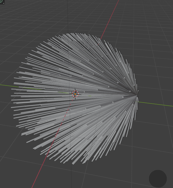
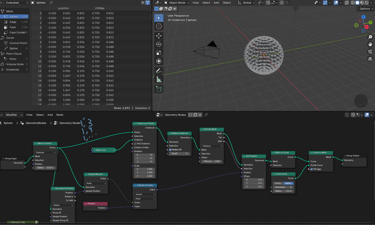
I'm trying to draw lines between vertices on this mesh. For this sphere it'll basically give me a wireframe, but I'm after a node setup that can include unattached meshes/faces/etc that are floating outside the main shape. I've got a couple images included here to show what my node setup is making happen, and where I've gotten stuck. (Mesh to Volume -> Volume to Mesh on their own can't give me the results I'm after)

I think what's happening is the extrusions are always starting at the same index point, regardless of what the other inputs are? That's the only explanation I can think of for them all connecting to one point instead of each other. So I either need to use another method entirely, or find a way to make sure the indeces are getting used in order, rather than going 1,2 -> 1,3 -> 1,4 -> etc, when I need 1,2 -> 2,3 -> 3,4 and so on. setupchanging geo prox node to faces domain, reducing radius of profile curve
$\endgroup$
0

2 Answers 2

3
$\begingroup$

(Using Blender 4.2.0)

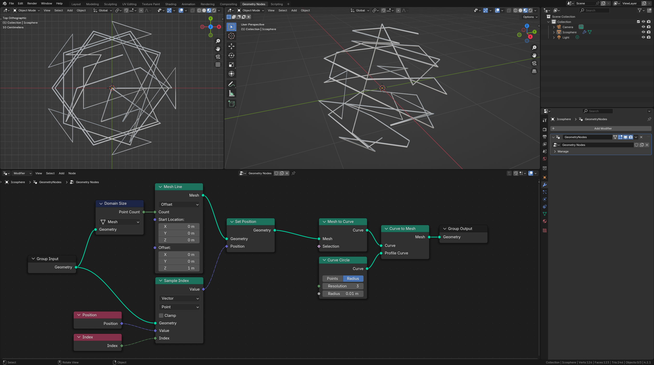
The following GN graph is transferring the Position of the input geometry points to the vertices of a Mesh Line to connect them following the Index order.

GN Graph

Resources:

(Blender 4.2.0+)


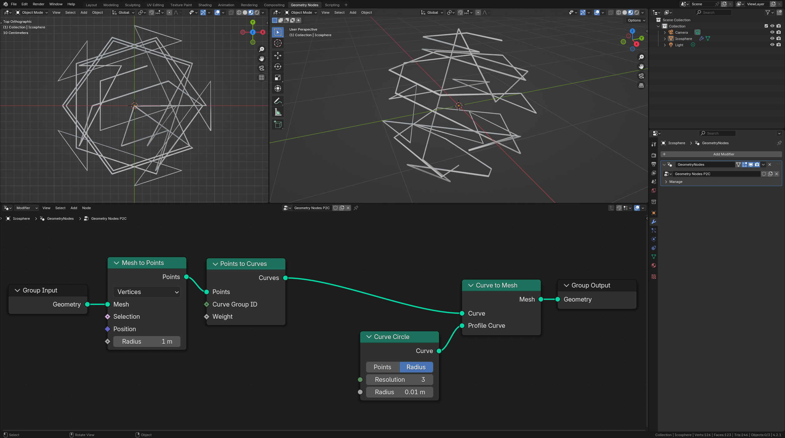
Edit - With just two nodes following Markus comment: Minimal GN graph

$\endgroup$
3
  • 1
    $\begingroup$ Could use "Points to curve" for this effect. $\endgroup$ Commented Aug 27 at 20:09
  • $\begingroup$ Very elegant solutions! $\endgroup$
    – Phrogz
    Commented Aug 27 at 20:28
  • $\begingroup$ Oh wow, that is perfect! I'm kind of embarrassed it could be this simple, but at the same time this means that it should run fast even in the complex situations I need it for. $\endgroup$ Commented Aug 28 at 6:09
2
$\begingroup$

Here's one solution; I'm a novice user, so might not be the cleanest.

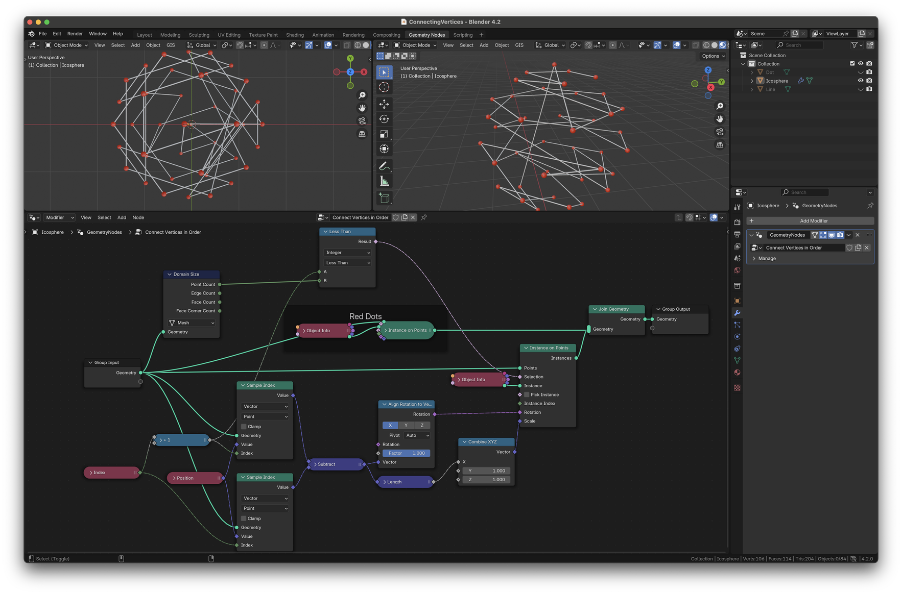
vertices of ico sphere connected by instances of a cylinder mesh

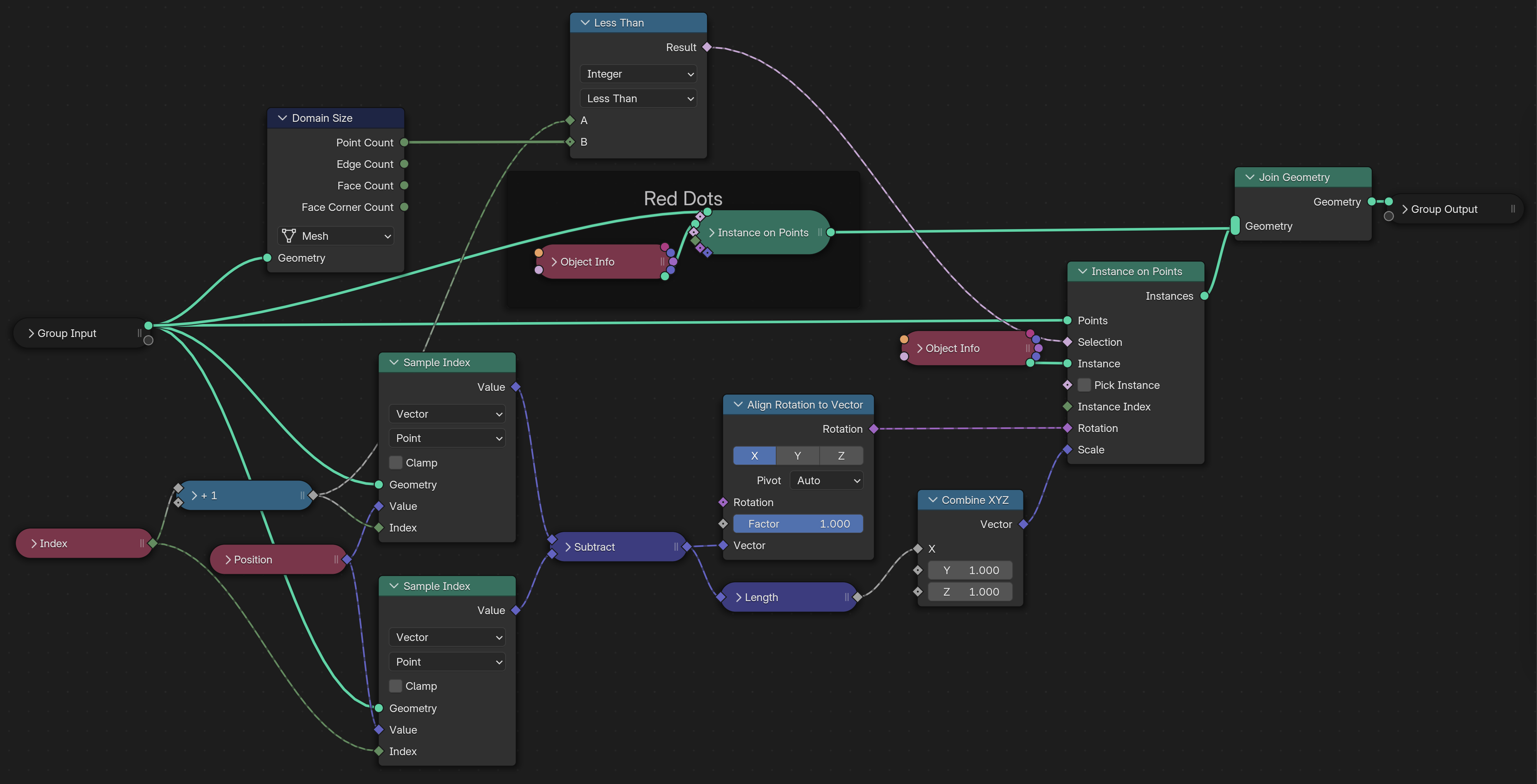
  • Use Sample Index with a Position input to select the position of two adjacent vertices, adding one to the Index input.

  • Subtract those positions, to compute the vector pointing from the first to the second.

    • Use Align Rotation to Vector to compute a rotation to use for the mesh that will connect the points.
    • Use the length of that vector to compute a scale factor to apply along the axis of the cylinder mesh.
  • Use Instance on Points to place an instance at the first vertex, rotated to point at the second, and scaled on the long axis to reach it.

    • Getting the correct scale requires the mesh to have unit length.
    • Use the Selection input to not place an instance on the very last vertex, by comparing the Index to the number of points in the geometry (using the Domain Size node).

For fun, I'm also dropping a red sphere on each vertex, just to make it easier to look at. Zooming in on the graph to make it easier to see:
just the graph

$\endgroup$

You must log in to answer this question.

Not the answer you're looking for? Browse other questions tagged .