Using the Add Mesh: Extra Objects add-on, I have set up a group of XYZ Math Surfaces Add > Mesh > Math Function > XYZ Math Surface which generate various parts of a single mesh object, with one parameter 0 ≤ G ≤ 1 that controls the shape of the mesh. I want to achieve the visual effect of animating that parameter. Is this possible?
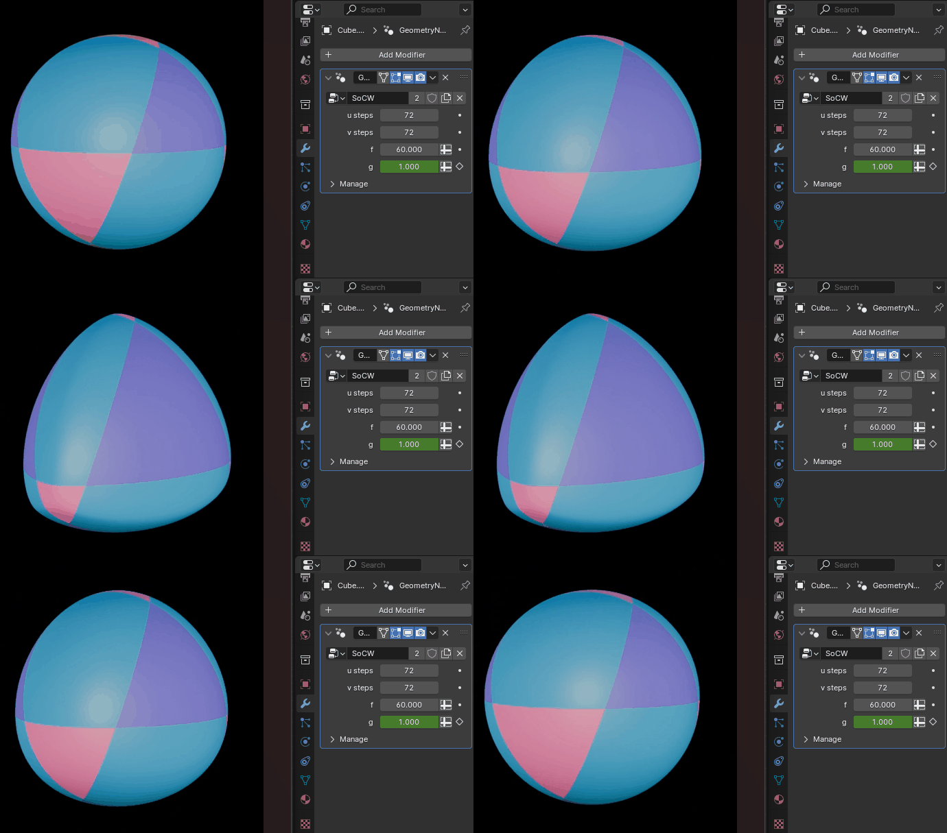
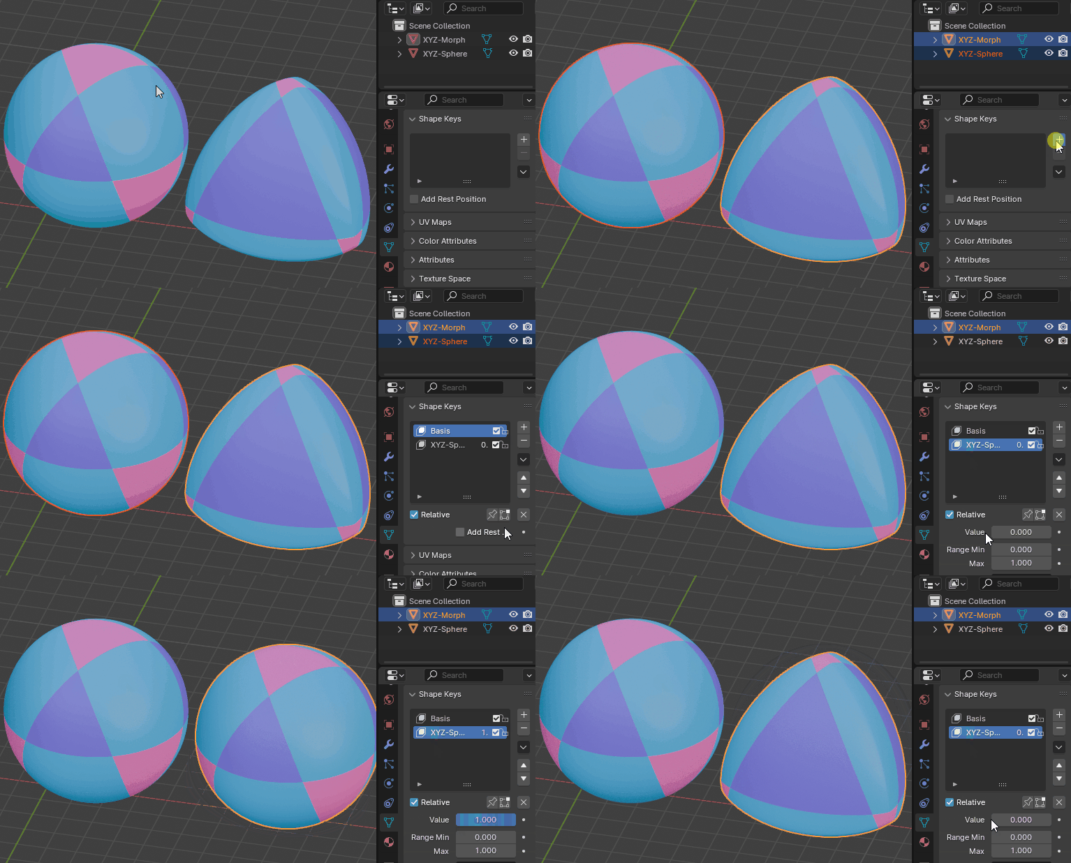
I tried using Shape Keys, but it isn't working how I expect. I created two separate mesh objects, one at each extreme of the parameter (G = 0 and G = 1). They should have identical topologies (i.e. the same number of vertices and the same arrangement of edges between vertices), differing only in the positions of the vertices. I selected both objects, went to the Shape Keys panel, selected the drop-down arrow, and selected "Join as Shapes", which created a Basis Shape Key and a modifier Shape Key. However, adjusting the "Value" slider for the Shape Key causes horrible distortions instead of a smooth transition. It seems like Blender isn't determining which vertices are equivalent between the meshes, resulting in many vertices that start next to one another ending up wildly separated, while other vertices that start separated end up becoming neighbors.
Is there a way to fix the Shape Keys setup? Or an alternative method to achieve the result I want?
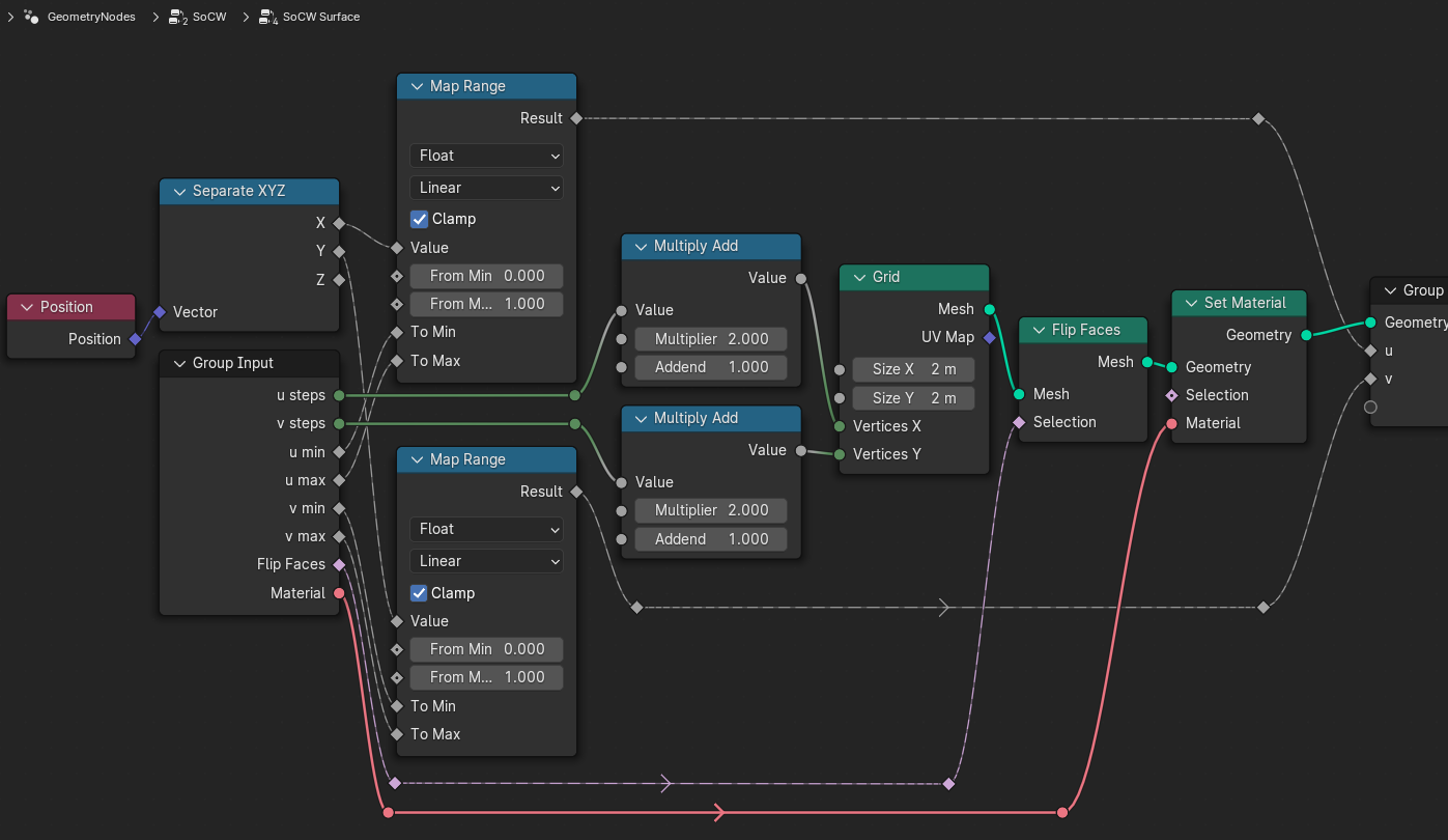
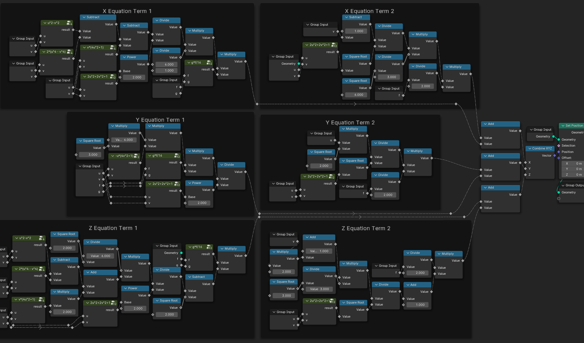
XYZ Math Surfaces to Mesh
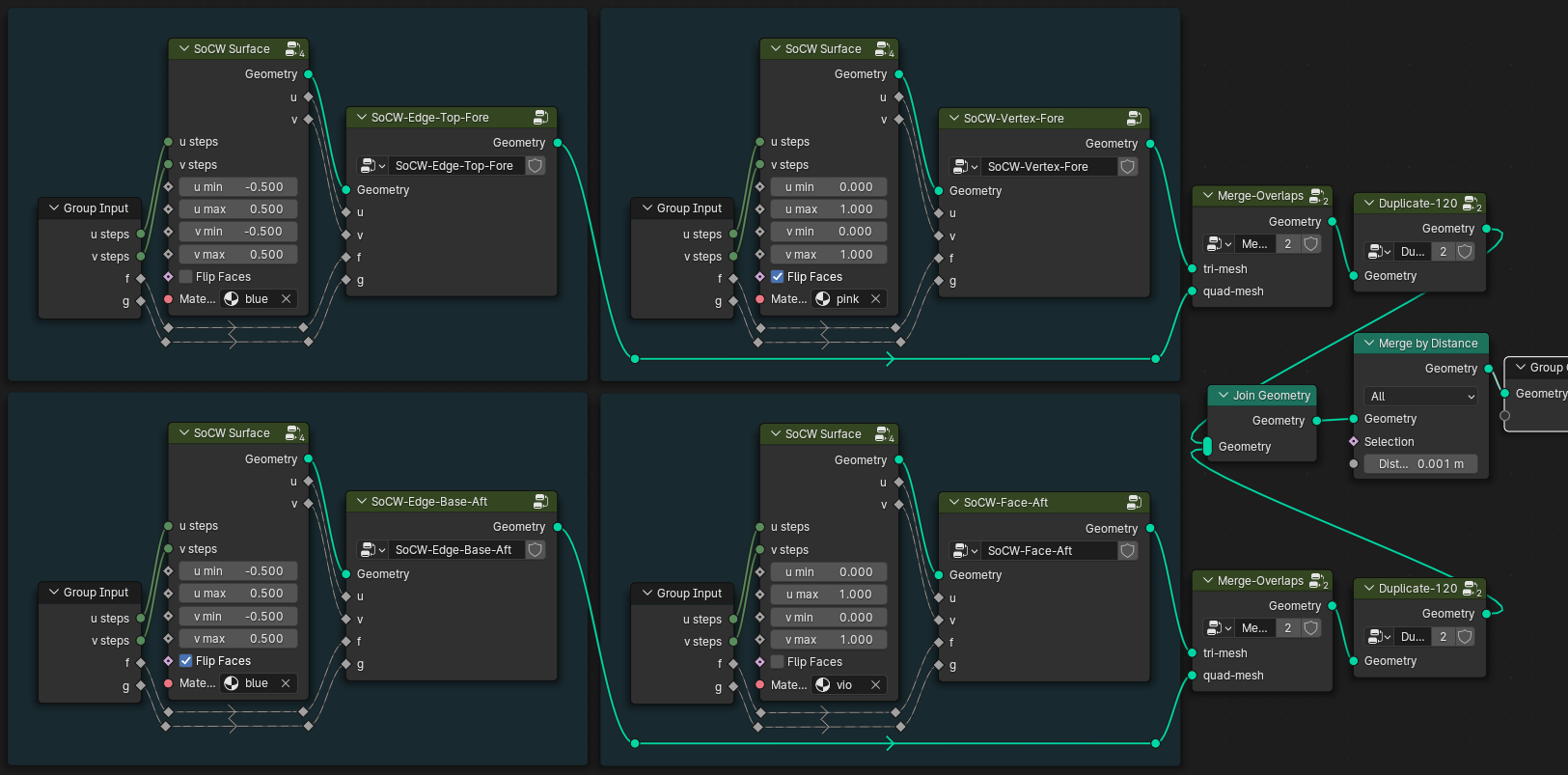
The setups for the XYZ Math Surfaces are as follows:
SoCW-Edge-Base-Aft
X equ: (g*f)/16*(6/1*(u**2 - v**2 - 2*(u**4 - v**4) - v*(4*u**2 + 1))/(2*u**2 + 2*v**2 + 1)**2) - (sqrt(6)/3*(1 - v)/sqrt(2*u**2 + 2*v**2 + 1))*f/2
Y equ: (g*f)/16*(6*sqrt(3)*(-u*(4*v**2 + 1))/(2*u**2 + 2*v**2 + 1)**2) - (sqrt(2)*(u)/sqrt(2*u**2 + 2*v**2 + 1))*f/2
Z equ: (g*f)/16*(6/sqrt(2)*(u**2 - v**2 - 2*(u**4 - v**4) + 2*v*(4*u**2 + 1))/(2*u**2 + 2*v**2 + 1)**2 - sqrt(2)) - (sqrt(3)/3*(1 + 2*v)/sqrt(2*u**2 + 2*v**2 + 1) - 1)*f/2
U min: -0.50
U max:  0.50
U stp: 72
V min: -0.50
V max:  0.50
V stp: 72
F equ:  2.00
G equ: [0.00 ↔ 1.00]

SoCW-Edge-Top-Fore
X equ: (g*f)/16*(6/1*(u**2 - v**2 - 2*(u**4 - v**4) - v*(4*u**2 + 1))/(2*u**2 + 2*v**2 + 1)**2) + (sqrt(6)/3*(1 - v)/sqrt(2*u**2 + 2*v**2 + 1))*f/2
Y equ: (g*f)/16*(6*sqrt(3)*(-u*(4*v**2 + 1))/(2*u**2 + 2*v**2 + 1)**2) + (sqrt(2)*(u)/sqrt(2*u**2 + 2*v**2 + 1))*f/2
Z equ: (g*f)/16*(6/sqrt(2)*(u**2 - v**2 - 2*(u**4 - v**4) + 2*v*(4*u**2 + 1))/(2*u**2 + 2*v**2 + 1)**2 - sqrt(2)) + (sqrt(3)/3*(1 + 2*v)/sqrt(2*u**2 + 2*v**2 + 1) + 1)*f/2
U min: -0.50
U max:  0.50
U stp: 72
V min: -0.50
V max:  0.50
V stp: 72
F equ:  2.00
G equ: [0.00 ↔ 1.00]

SoCW-Face-Aft
X equ: (g*f)/16*(3/2*((u**2 + v**2)*(3 - (u + v - 1)**2) - 2*(u**2*v**2 - 2*(u*v - u - v) - 1))/(u**2 + u*v + v**2 - u - v + 1)**2) - (sqrt(3)/6*(u + v + 2)/sqrt(u**2 + v**2 + u*v - u - v + 1))*f/2
Y equ: (g*f)/16*(3/2*sqrt(3)*((u**2 - v**2)*(1 + (u + v - 1)**2))/(u**2 + u*v + v**2 - u - v + 1)**2) + (1/2*(u - v)/sqrt(u**2 + v**2 + u*v - u - v + 1))*f/2
Z equ: (g*f)/16*(3/2*sqrt(2)*((u**2 + v**2)*((u + v - 1)**2) - (u**2*v**2 - 2*(u*v - u - v) - 1))/(u**2 + u*v + v**2 - u - v + 1)**2 - sqrt(2)) - (sqrt(6)/3*(u + v - 1)/sqrt(u**2 + u*v + v**2 - u - v + 1) - 1)*f/2
U min:  0.00
U max:  1.00
U stp: 72
V min:  0.00
V max:  1.00
V stp: 72
F equ:  2.00
G equ: [0.00 ↔ 1.00]

SoCW-Face-Base
X equ: (g*f)/16*(3/2*((u**2 + v**2)*(1 + (u + v - 1)**2) - 2*(u**2*v**2 - 2*(u*v - u - v) - 1))/(u**2 + u*v + v**2 - u - v + 1)**2) - (sqrt(3)/6*(3*u + 3*v - 2)/sqrt(u**2 + v**2 + u*v - u - v + 1))*f/2
Y equ: (g*f)/16*(3/2*sqrt(3)*((u**2 - v**2)*(1 + (u + v - 1)**2))/(u**2 + u*v + v**2 - u - v + 1)**2) + (1/2*(u - v)/sqrt(u**2 + v**2 + u*v - u - v + 1))*f/2
Z equ: (g*f)/16*(3/2*sqrt(2)*((u**2 + v**2)*(2 - (u + v - 1)**2) - (u**2*v**2 - 2*(u*v - u - v) - 1))/(u**2 + u*v + v**2 - u - v + 1)**2 - sqrt(2)) + (sqrt(6)/3*(-1)/sqrt(u**2 + u*v + v**2 - u - v + 1) + 1)*f/2
U min:  0.00
U max:  1.00
U stp: 72
V min:  0.00
V max:  1.00
V stp: 72
F equ:  2.00
G equ: [0.00 ↔ 1.00]

SoCW-Vertex-Fore
X equ: (g*f)/16*(3/2*((u**2 + v**2)*(3 - (u + v - 1)**2) - 2*(u**2*v**2 - 2*(u*v - u - v) - 1))/(u**2 + u*v + v**2 - u - v + 1)**2) + (sqrt(3)/6*(u + v + 2)/sqrt(u**2 + u*v + v**2 - u - v + 1))*f/2
Y equ: (g*f)/16*(3/2*sqrt(3)*((u**2 - v**2)*(1 + (u + v - 1)**2))/(u**2 + u*v + v**2 - u - v + 1)**2) - (1/2*(u - v)/sqrt(u**2 + u*v + v**2 - u - v + 1))*f/2
Z equ: (g*f)/16*(3/2*sqrt(2)*((u**2 + v**2)*(0 + (u + v - 1)**2) - (u**2*v**2 - 2*(u*v - u - v) - 1))/(u**2 + u*v + v**2 - u - v + 1)**2 - sqrt(2)) + (sqrt(6)/3*(u + v - 1)/sqrt(u**2 + u*v + v**2 - u - v + 1) + 1)*f/2
U min:  0.00
U max:  1.00
U stp: 72
V min:  0.00
V max:  1.00
V stp: 72
F equ:  2.00
G equ: [0.00 ↔ 1.00]

SoCW-Vertex-Top
X equ: (g*f)/16*(3/2*((u**2 + v**2)*(1 + (u + v - 1)**2) - 2*(u**2*v**2 - 2*(u*v - u - v) - 1))/(u**2 + u*v + v**2 - u - v + 1)**2) + (sqrt(3)/6*(3*u + 3*v - 2)/sqrt(u**2 + v**2 + u*v - u - v + 1))*f/2
Y equ: (g*f)/16*(3/2*sqrt(3)*((u**2 - v**2)*(1 + (u + v - 1)**2))/(u**2 + u*v + v**2 - u - v + 1)**2) - (1/2*(u - v)/sqrt(u**2 + v**2 + u*v - u - v + 1))*f/2
Z equ: (g*f)/16*(3/2*sqrt(2)*((u**2 + v**2)*(2 - (u + v - 1)**2) - (u**2*v**2 - 2*(u*v - u - v) - 1))/(u**2 + u*v + v**2 - u - v + 1)**2 - sqrt(2)) - (sqrt(6)/3*(-1)/sqrt(u**2 + u*v + v**2 - u - v + 1) - 1)*f/2
U min:  0.00
U max:  1.00
U stp: 72
V min:  0.00
V max:  1.00
V stp: 72
F equ:  2.00
G equ: [0.00 ↔ 1.00]
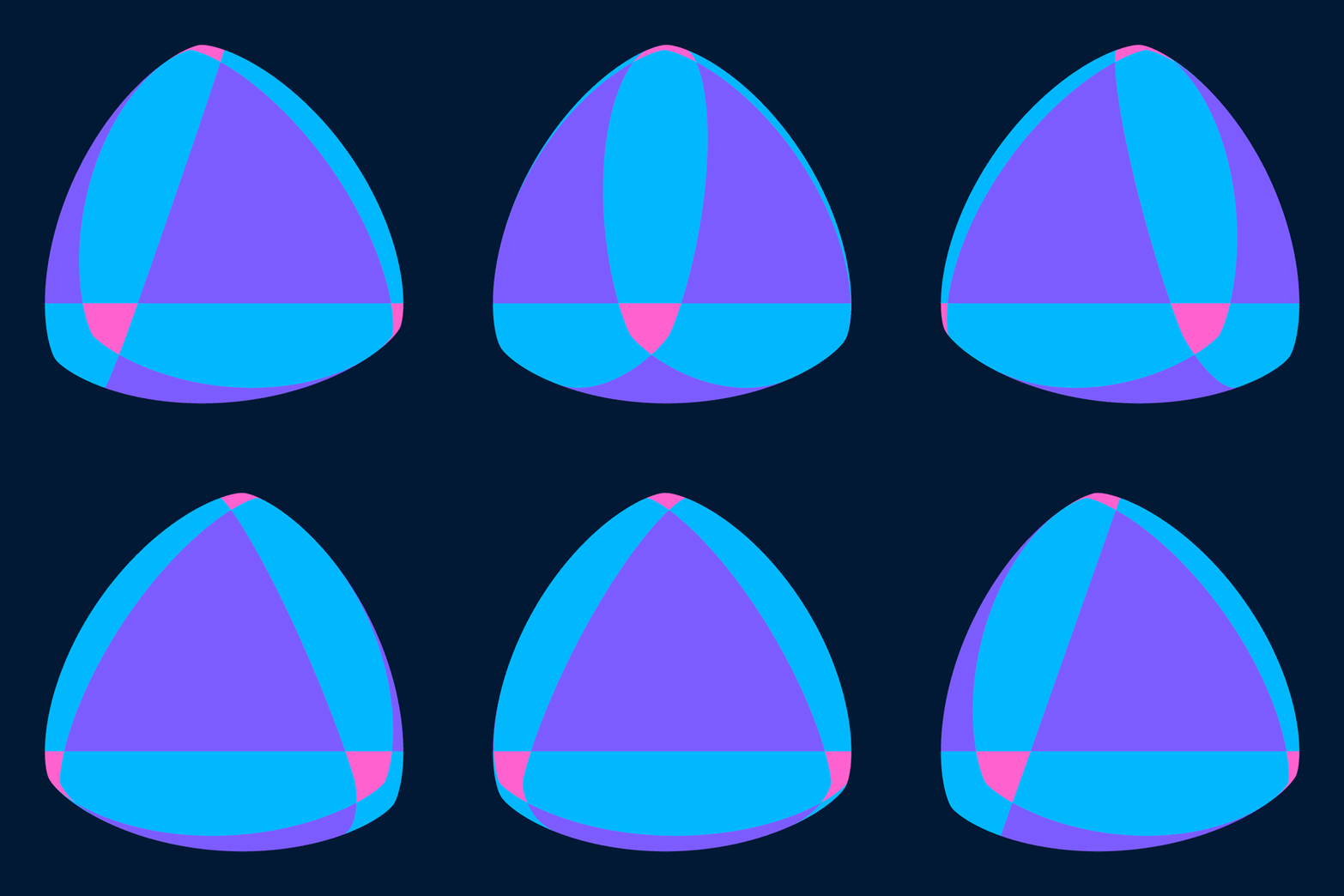
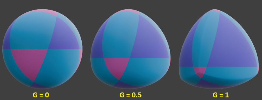
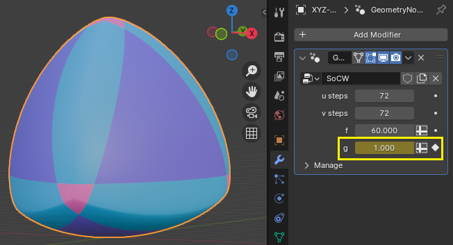
The F parameter controls the total width of the combined mesh, while the G parameter controls the uniformity of curvature from 0 (completely uniform curvature, generating a sphere) to 1 (maximum variation in curvature). In the following two GIFs, the "Edge" surfaces have been colored cyan, the "Face" surfaces have been colored purple, and the "Vertex" surfaces have been colored magenta.
The "Edge" surfaces are triangulated with the "Shortest Diagonal" Quad Method, while the "Face" and "Vertex" surfaces are triangulated with the "Fixed Alternate" Quad Method. After triangulation, the portions of the "Face" and "Vertex" surfaces which overlap with the "Edge" surfaces are deleted. To get the complete mesh, the surfaces whose names end in "Fore" or "Aft" must be duplicated twice, with each duplicate rotated 120° about the z-axis.
All surfaces (four faces, four vertices, and six edges) are combined into a single mesh object with Object > Join. The boundary-vertices are joined to make a single contiguous mesh with Merge By Distance (for F = 2, I found that a distance of 0.000001 m is sufficiently small to avoid merging vertices which are not on the boundaries). Finally, the Normal vectors are recalculated with Shift+N to ensure they all point outwards.
Here is a link to a Blender file with both meshes:


