2
$\begingroup$
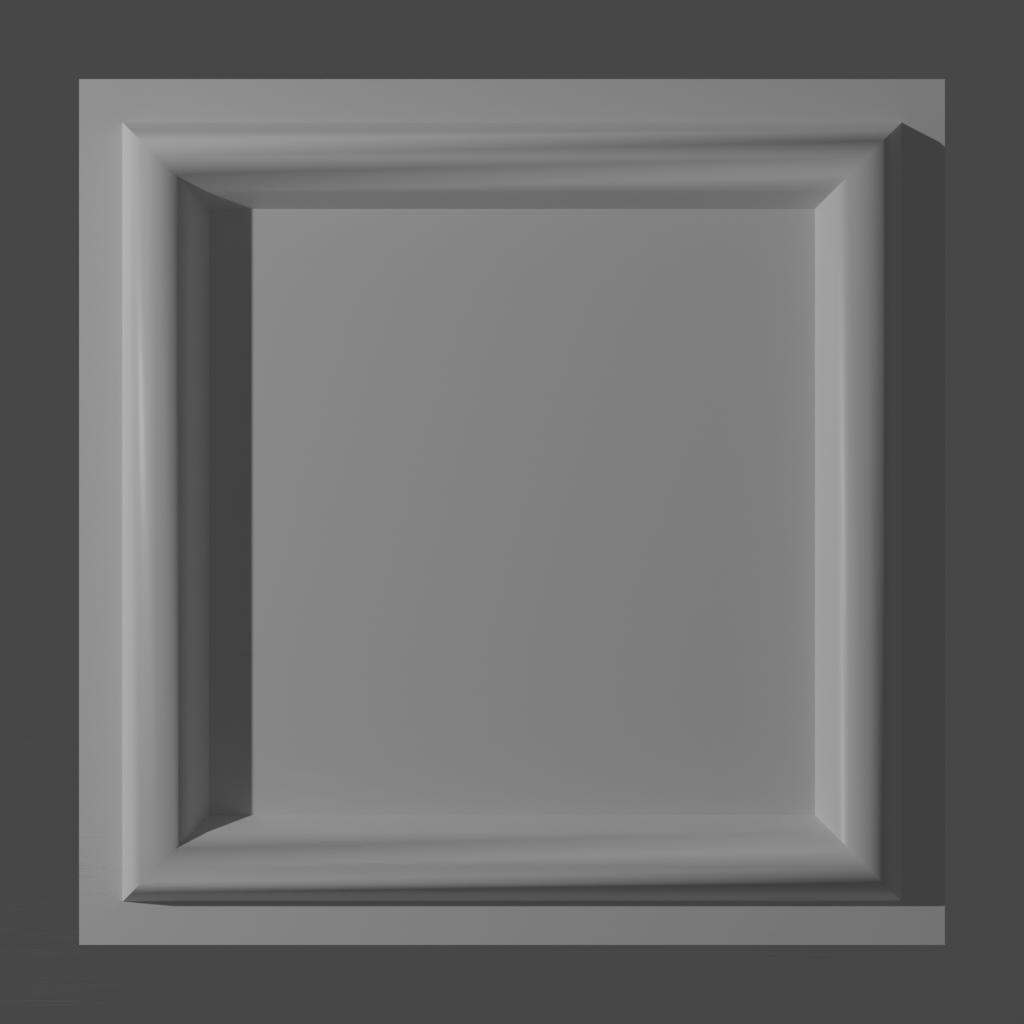
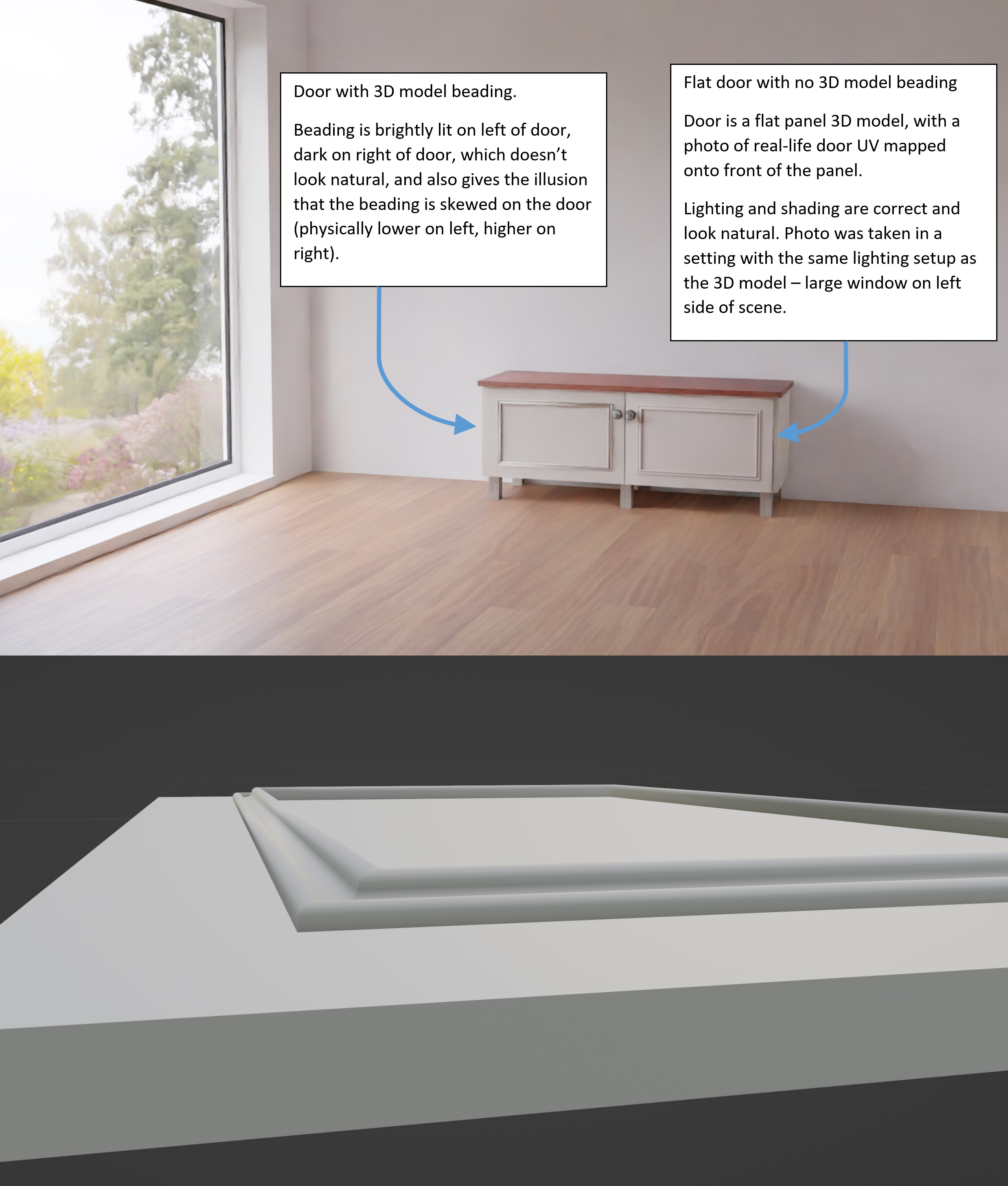
Hi all, I’m creating some furniture models based on some real-life pieces of furniture. There’s a type of cabinet door where the shading just doesn’t look right when I render the model. The door is essentially a flat panel with some beading/moulding on the front of the panel. I’ve created a 3D model of the panel and beading in blender, but when I render the door in a room scene, the light/shade on the beading does not look natural/correct. The beading is brightly lit near the light source in the room (window with HDRI outside), and very dark away from the light source, with a fairly pronounced step-change between the light and dark areas. I’ve included a rendered picture that shows this (door on left of picture). For reference, the picture also shows a door (door on right of picture) that is a flat panel with no 3D model beading, but the panel has a photo of the real-life furniture door UV mapped onto it. The light and shade on this door look correct, because the mapped image texture is a photo that was taken in real-world lighting conditions.

I’ve also included a close-up of the 3D model of the beading. Note that the shape of the beading is straight and uniform, so the light/shade on the rendered beading should also be relatively uniform, as per the real-life photo image texture.

The attached rendered image was created with only 5 samples (for speediness), but I also tried a render at 50 samples to increase the detail, but this doesn’t change the beading lighting problem.

Can anyone help me to figure out how to get the 3D model of the beading to look right?

Many thanks!

Andy_C
enter image description here

enter image description here

$\endgroup$
4
  • $\begingroup$ Did you project the image from view? I would have to look at the.blend file but maybe you could lower the right side so it looks correct even if it's not. Sorry I can't do more atm. $\endgroup$
    – blend
    Commented Aug 31, 2022 at 18:09
  • $\begingroup$ I think it could be just the specularity, shininess, creating the illusion, assuming you've checked normals, etc. Try rougher? $\endgroup$
    – Robin Betts
    Commented Aug 31, 2022 at 18:51
  • $\begingroup$ This could be a low-poly object that is shaded smooth and the normals are being interpolated over a wide area. $\endgroup$ Commented Aug 31, 2022 at 19:47
  • $\begingroup$ Hi Blend, Robin, and Allen... I'm relatively new to Blender so I'm learning about normals... I'd originally used shade smooth on the beading, but I've now tried shade flat and that improves the look of the rendered beading. I've looked at the normals and they all seem to be pointing in the correct direction for each face - although I'm not quite sure what to look for that might be wrong? I've tried setting roughness and specular of the surface material to 0 (to try to counteract the apparent shine on the bright area of the beading), but this has little effect on the problem. Many thanks! $\endgroup$
    – Andy_C
    Commented Sep 1, 2022 at 12:51

1 Answer 1

2
$\begingroup$

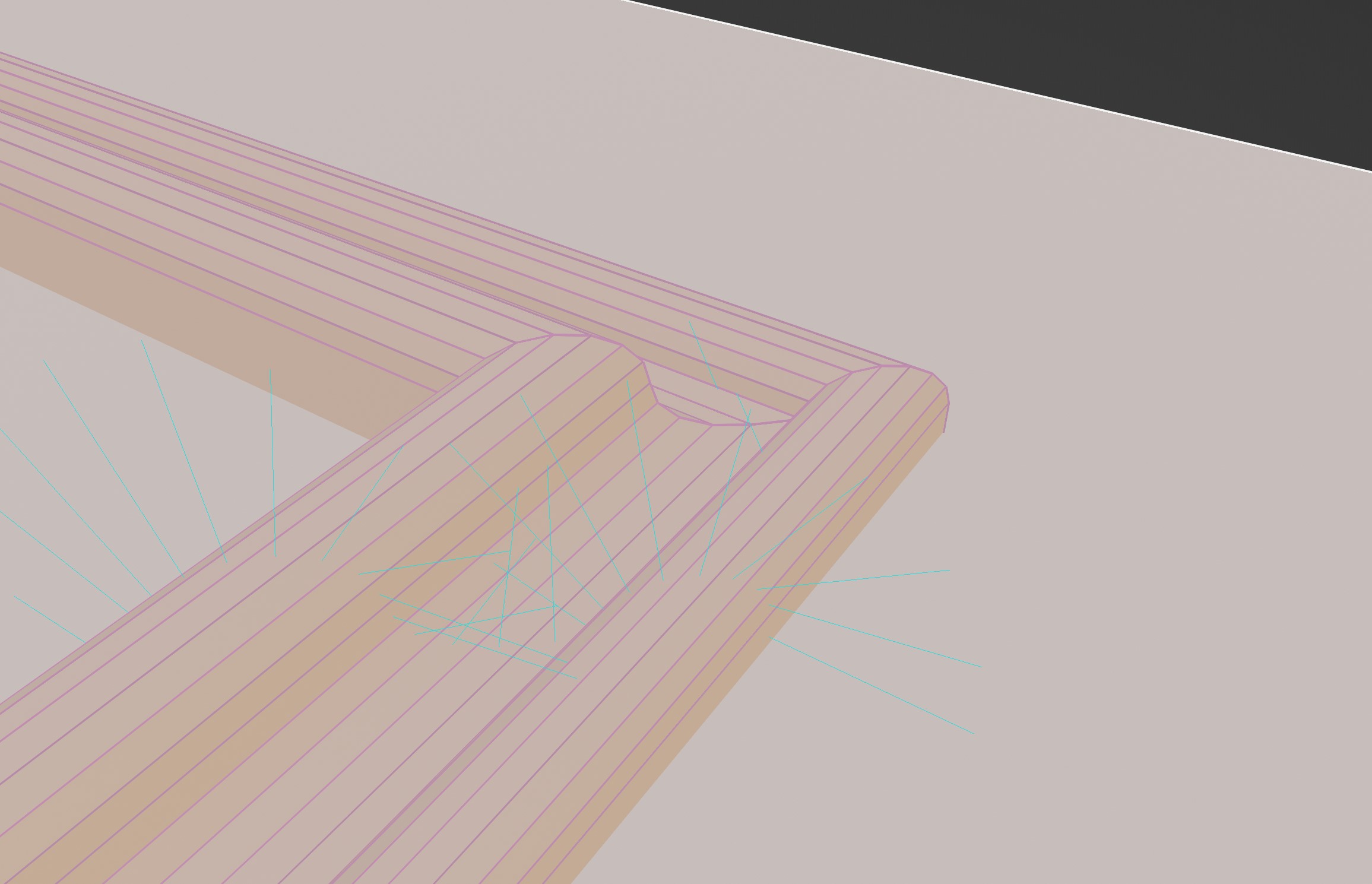
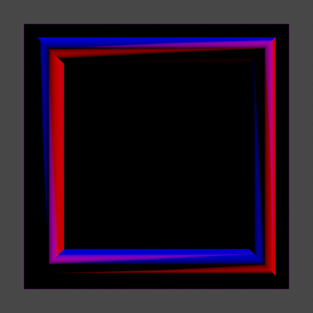
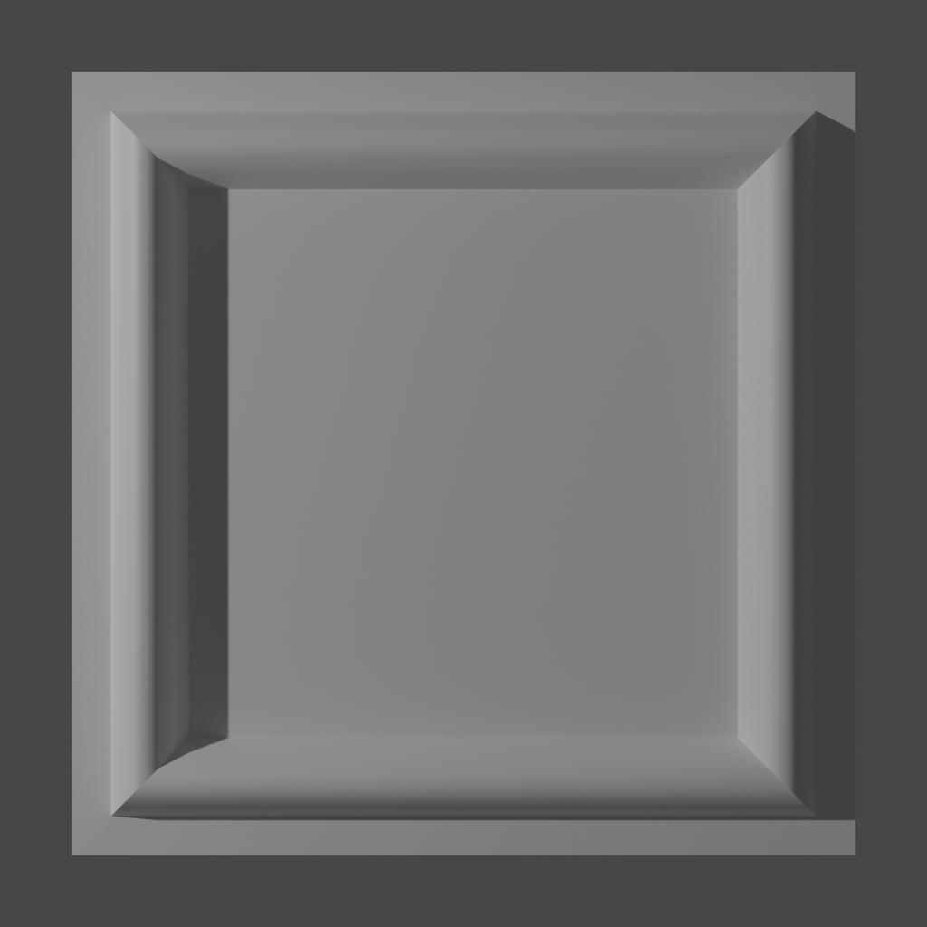
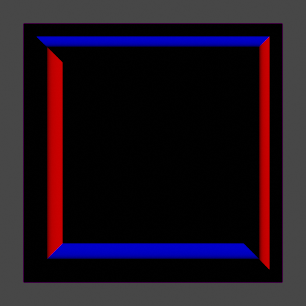
The normals along each face are being interpolated from the corner values, leading to a bulging effect. In addition, because the normal at the corners of each face differ significantly from each other, triangularization results in discontinuities.

Bad Normals

Bad Normals

Bad Normals

You can fix this problem by adding a cut or support loop on each side of a crease, marking the edges there "sharp", or a variety of other techniques:

Good Normals Good Normals Good Normals

$\endgroup$
4
  • 1
    $\begingroup$ nicely spotted :). agree, it could use a bit of bevel modifier on the sharp edges $\endgroup$ Commented Sep 1, 2022 at 9:44
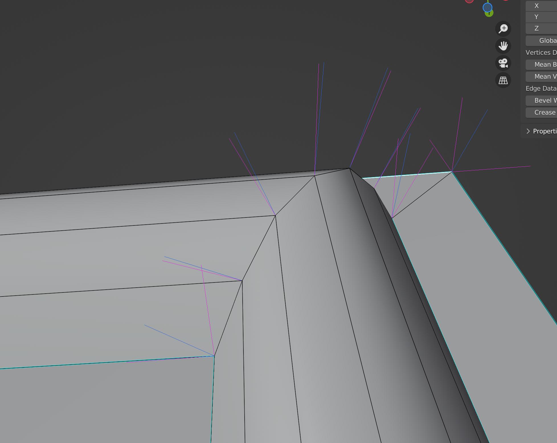
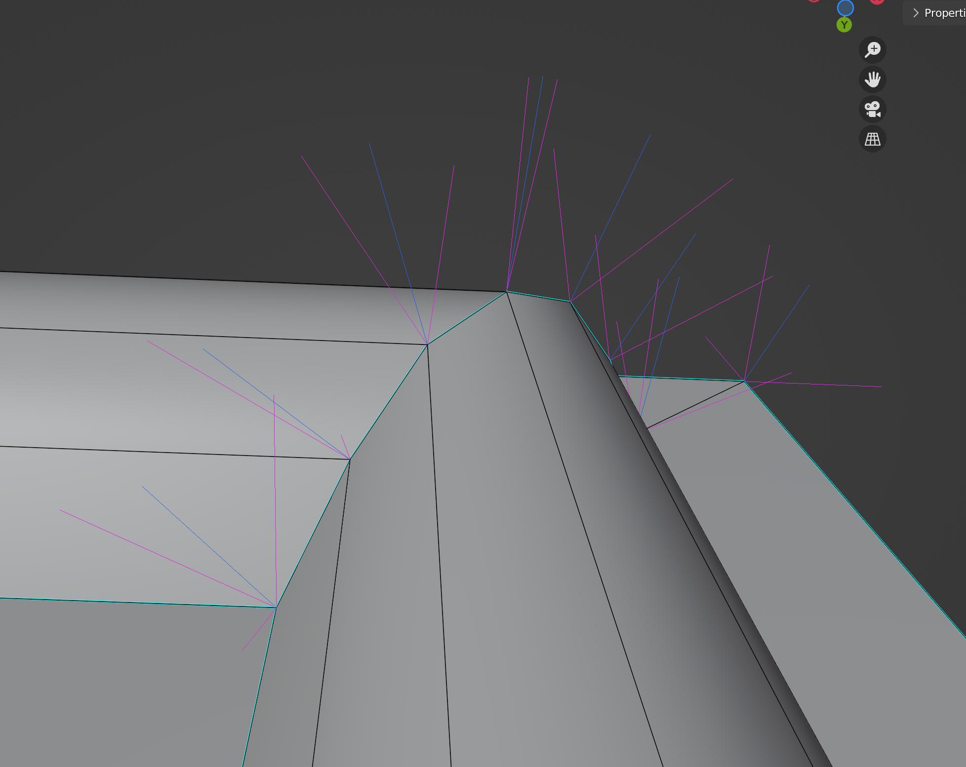
  • $\begingroup$ Hi MooseBoys, thanks for your detailed reply - you've made the situation much clearer for me. I've added a picture of the normals to my original post (not sure how to add a picture to this comment?). Apologies, the colour of the normals makes them hard to see - is there a way to change their colour? Do you see anything wrong with the normals in my model? Also, you said that a fix for the problem would be to add "a cut or support loop on each side of a crease, marking the edges there "sharp"" - can you tell me how to do this (I'm new to a lot of this but keen to learn). Many thanks again. $\endgroup$
    – Andy_C
    Commented Sep 1, 2022 at 13:17
  • $\begingroup$ @Andy_C In your updated screenshot, those are face normals - but for low-poly modeling you definitely want to show vertex-per-face normals instead. That will show the pink lines from my screenshot. To set an edge as "sharp", select it in Edit mode, then go to Edge > Mark sharp. Then update normals using e.g. Mesh > Normals > Average > Face Area. This will set smooth normals except along "sharp" edges, which will be split. $\endgroup$
    – MooseBoys
    Commented Sep 3, 2022 at 1:10
  • $\begingroup$ Many thanks Mooseboys... really good and useful explanation again, and you've really helped me to understand the situation further. The render is looking pretty decent now - I really appreciate your help. $\endgroup$
    – Andy_C
    Commented Sep 5, 2022 at 14:53

You must log in to answer this question.

Not the answer you're looking for? Browse other questions tagged .