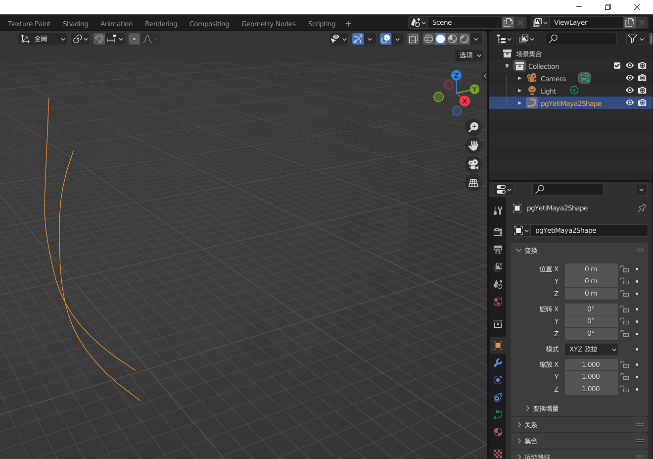
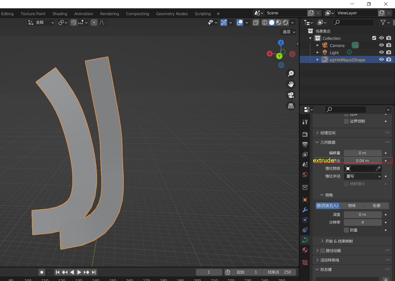
Is this what you want?
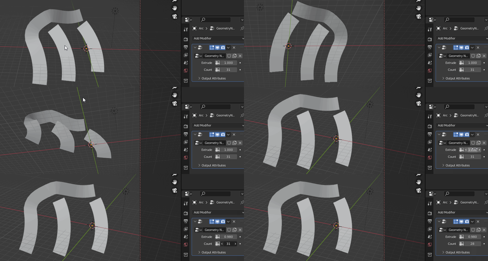
I made that with the Geometry Nodes Modifier.
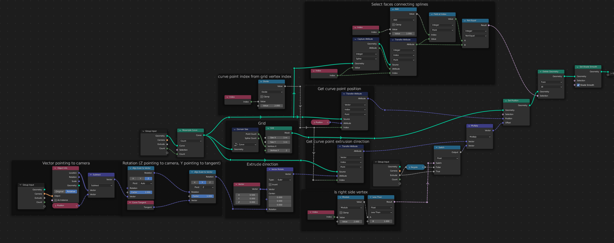
This node tree will extrude any spline. The extrusion is oriented to the camera while still following the curve tangent.
What it does is create a face line position it in the curve points with an offset to the sides, the sides being the $X$ axis of a rotation in which the $Z$ axis points to the camera, while the $Y$ axis points to the curve tangent.

$$\text{The Way It Works}$$
First, a grid is created. Y vertices = $2$; X vertices = curve's point count.
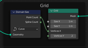
That way, it's vertices are ordered as this image shows:
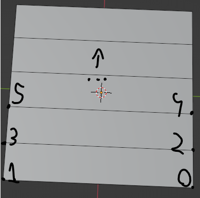
The grid's vertices are ordered as: indexes $0$ and $1$ are for right and left of the curve point with index $0$; indexes $2$ and $3$ are for right and left of the curve point with index $1$; and it goes that way for all...
Now it needs to set the vertices of the grid to the curve position using the index to select the curve point. For a point in the grid, it's position is set to the position of the curve point with index equal to $\lfloor i \mod 2\rfloor$ where $i = \text{vertex index}$. The position is accessed using a Transfer Attibute Node with the curve as source and index as mapping.

Now the pair of vertices of every curve point is in the curve point's positon. The next step is to offset them to the extrusion direction, which is calculated by the following way:
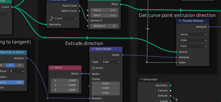
For a point in the curve, a vector pointing to the camera is calculated by subtracting the point position from the camera position. After that, the vector is used to create a rotation that points the $Z$ axis to the camera. Then it aligns the rotation's $Y$ axis with the curve point's tangent, here it uses the $Z$ axis as pivot so it doesn't change.

the resulting rotation's $X$ axis, now points to the side in relation to the camera and curve direction.
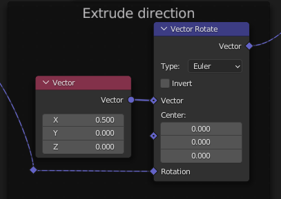
Now the vector $(0.5, 0.0, 0.0)$ is rotated with the calculated rotation, this is now the extrusion direction. $X$ is $0.5$ because the curve point is the extrusion center, so the left and right vertices needs to be transformed by half the extrusion length, but opposite directions.
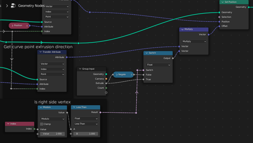
Now for offsetting the vertices of the grid, we first transfer the offset from the curve's points using the same way as for positions.
Before plugging the extrusion direction in the offset socket, it is first multiplied by: extrude length, if vertex is from right side; If not, negated extrude length.
Now faces are facing the camera, but, if there's multiple splines, they will be connected:
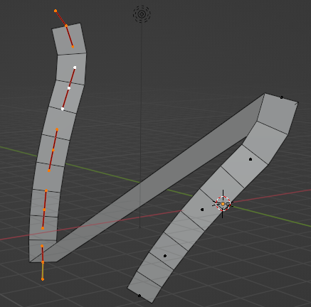
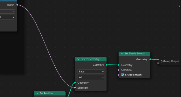
These connecting faces needs to be deleted, so a way to is needed.
First, the spline index is captured in the curve, with that it's possible to tell from which spline a point comes from.
A face connecting splines is the last face of it's spline index, so we can select them by verifying if the spline index of the next face is different.
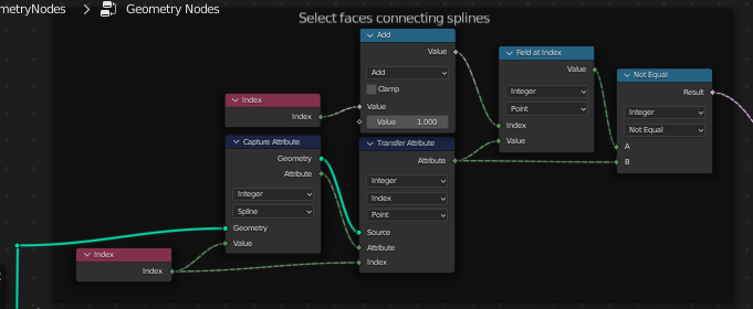
And finally faces are deleted using the selection of connecting faces.
