17
$\begingroup$

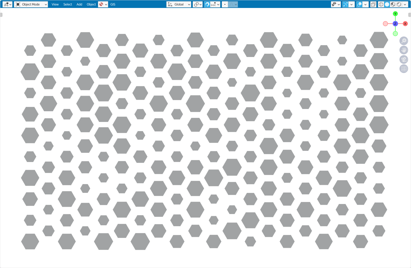
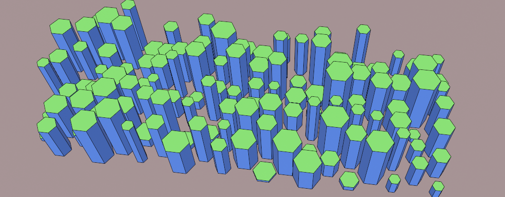
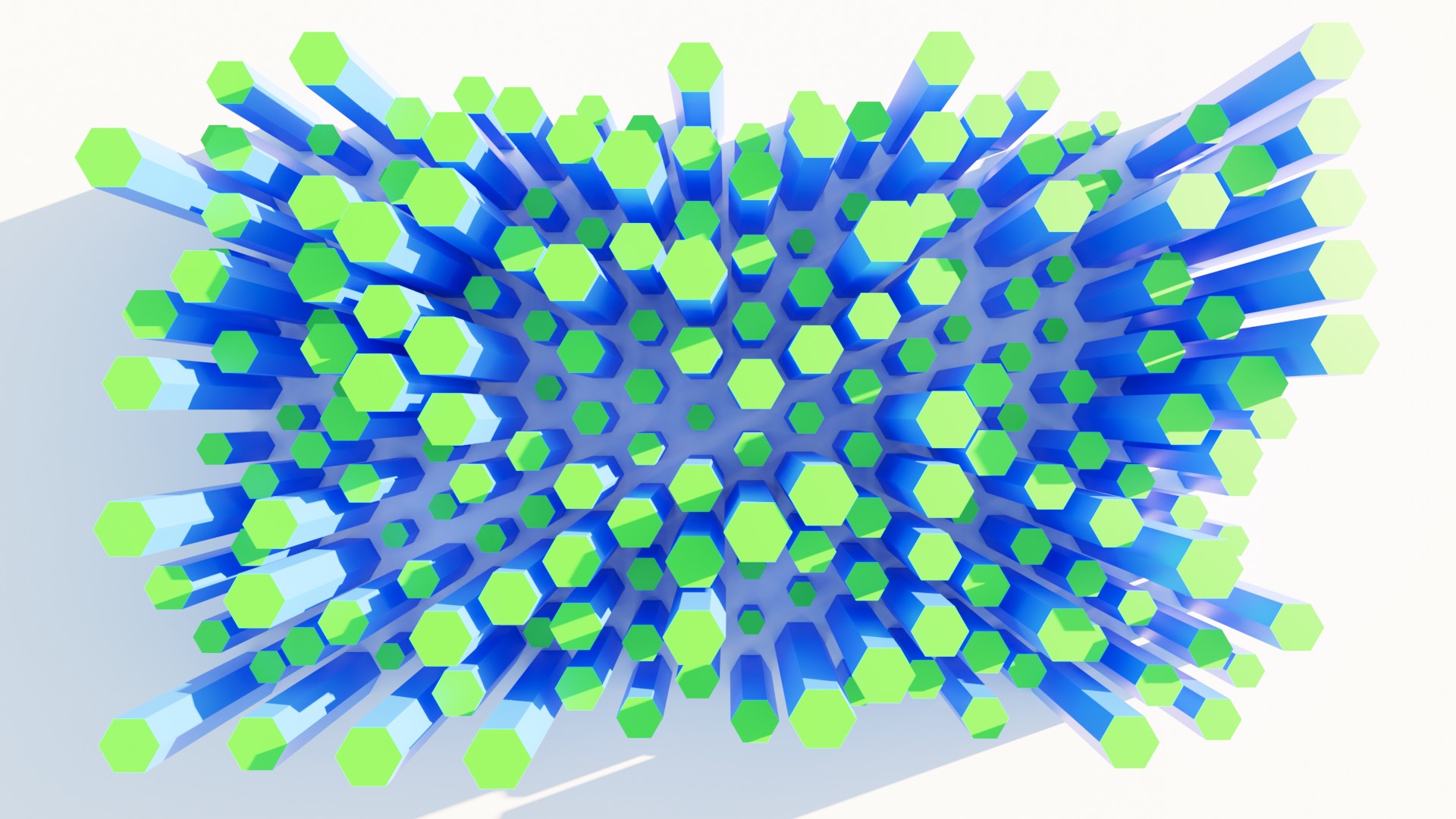
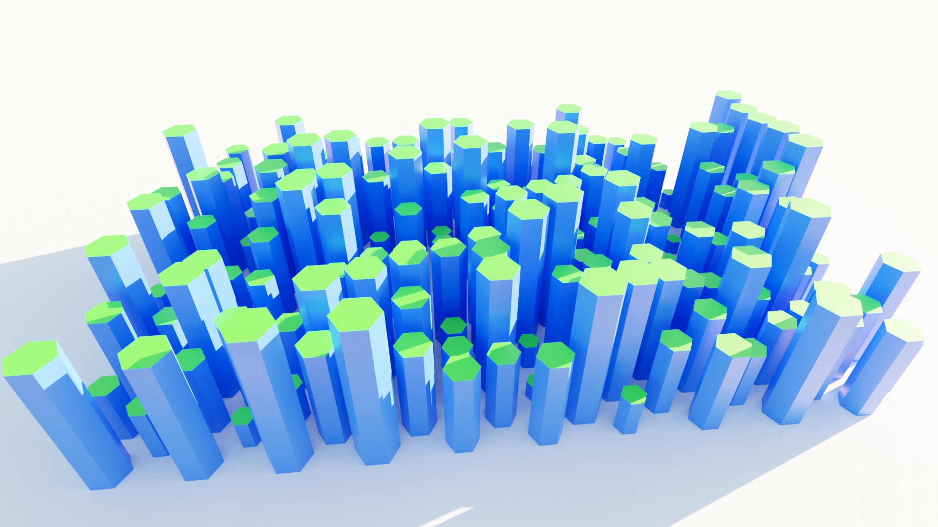
I am looking for the simplest possible solution to create a hexagonal structure like this with Geometry Nodes:

Hexagonal structure with Geometry Nodes

Which solutions are there?

Bonus Tasks:

  • Additionally I want the hexagons to have different sizes and be extruded with different heights.
  • Furthermore, I want the top faces to have a different material than the sides.
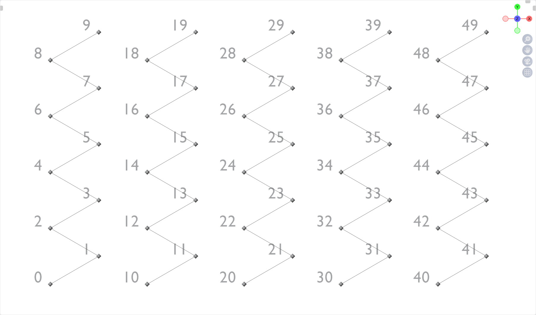
  • It would be great if the indexes of the instances are not jumbled, but are continuous.
$\endgroup$
5
  • 1
    $\begingroup$ i really like your question, but it is also a bit opinioned based...i think. The question is: what is the easiest? with the least nodes used? or the one which is easiest to understand? and even that is subjective...so maybe (i would just suggest) delete this one here : "Which way is the easiest/fastest/leanest?" so that people won't close your question because of "opinioed based" ...would be a pity $\endgroup$
    – Chris
    Commented May 19, 2022 at 11:30
  • $\begingroup$ @Chris As always from your side: a good point! $\endgroup$
    – quellenform
    Commented May 19, 2022 at 11:35
  • $\begingroup$ thanks ;) love your solution....curious about other answer ;) +2 (one for question, one for answer) $\endgroup$
    – Chris
    Commented May 19, 2022 at 11:35
  • 1
    $\begingroup$ Isn't even close to a true answer as it has pentagons (not to mention the shape), but a subdivided icosphere passed to dual-mesh is ALMOST a sphere made of tesselated hexagons. Close enough to be fun to play with if you want something hexish fast. There's pentagons at the 5-poles though, which the icosphere has a few of. $\endgroup$
    – Ben
    Commented May 19, 2022 at 15:54
  • $\begingroup$ This tuotrial talks a good deal about how building hex meshs, convering the second half of your first bonus as well as your second bonus. $\endgroup$ Commented May 19, 2022 at 18:23

6 Answers 6

19
$\begingroup$

Hexagonal structure with Geometry Nodes - Render 1

What all hexagonal structures have in common:

  • They all consist of six equilateral triangles.
  • The height of a triangle always has the value $0.86602540378443864676372317075294$ for a side length of $1$.
  • The hexagons are always offset from each other by $1.5$ on one axis, and $3$ on the other axis for an equilateral triangle with side length $1$.

This is convenient because then we don't need to recalculate these values each time, we just create the structure based on these values and scale the result.

I obtain the value for the height of the equilateral triangle with the formula $h={\frac {\sqrt {3}}{2}}\cdot r$.
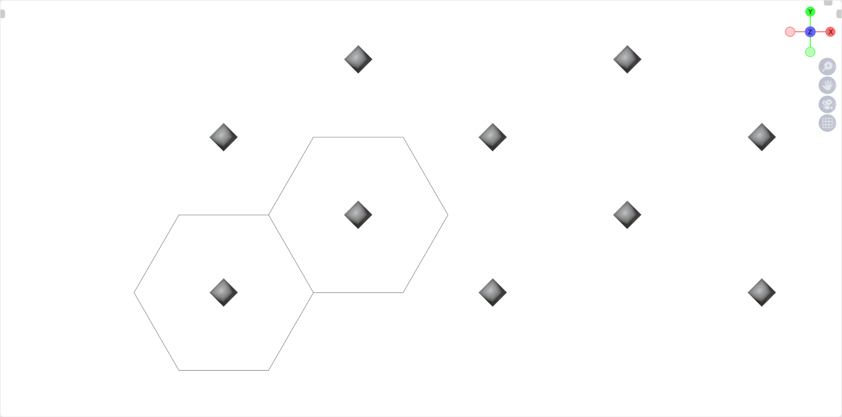
enter image description here

Here I present three variations, all of which achieve the same result:

  • One is based only on the creation of a single Mesh Line.
  • Another is based on creating a Mesh Line, which is instantiated along another.
  • And the third variant simply creates a Grid where the points are moved.

The advantage of all these variants is that the indices are continuous and there is no shifting.

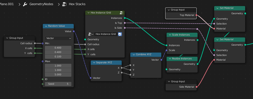
All three achieve the bonus goal of scaling and materials in the following way:
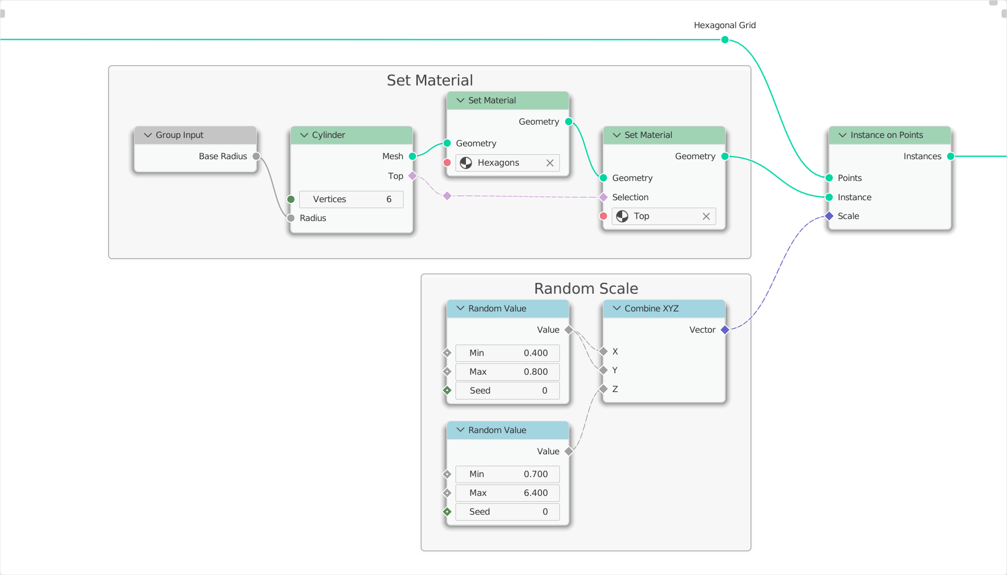
enter image description here

Variant 1

Based on a single Mesh Line
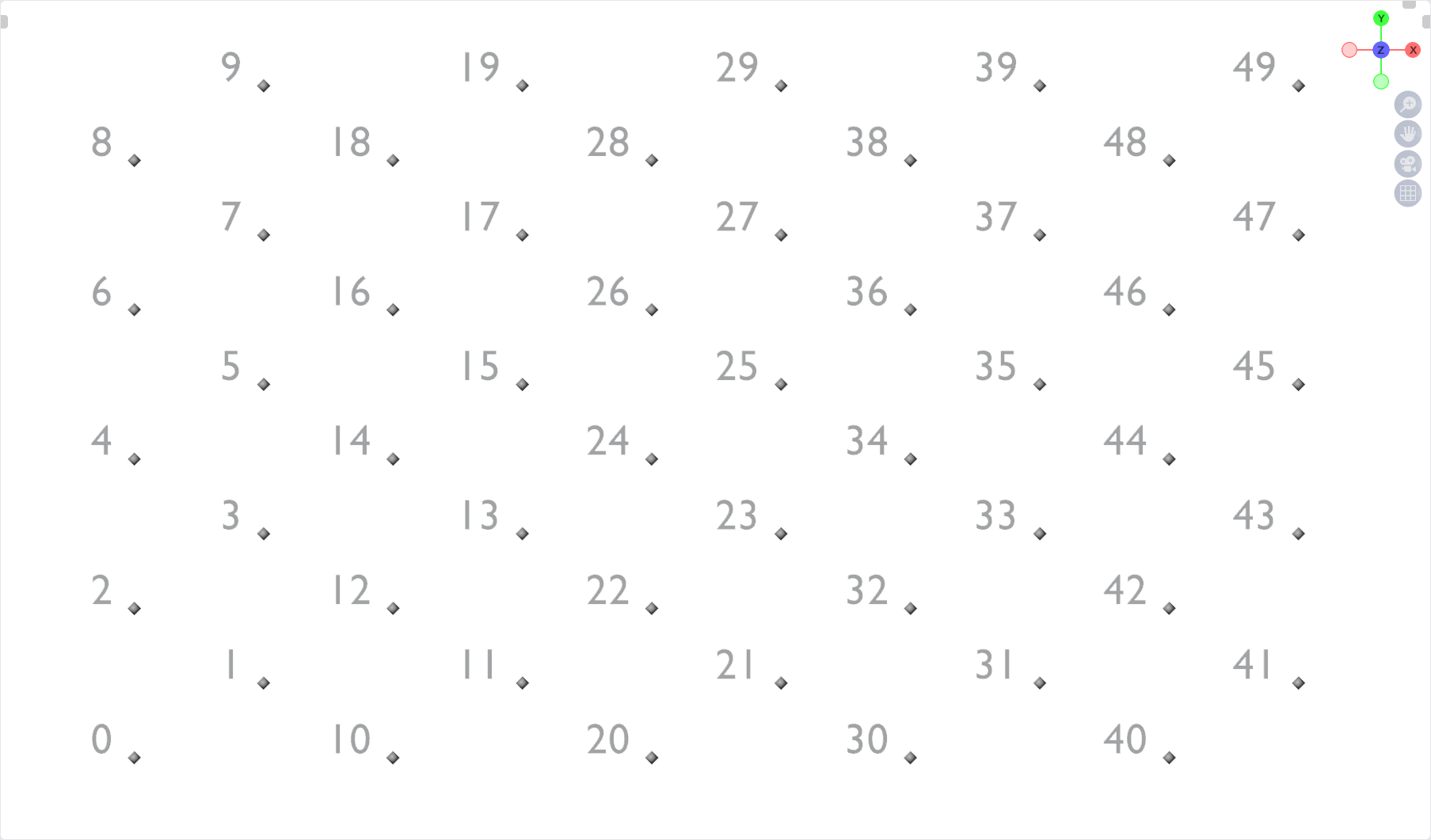
enter image description here

The variant that creates the least amount of excess geometry is the one that creates only one Mesh Line for instantiation.

I duplicate its points with Duplicate Elements and thus achieve the necessary number of points for the hexagons.

Every second row is then simply shifted to the right by $1.5$ and every row is incrementally shifted up by $0.86602540378443864676372317075294$.

This gives me the points for instantiation.

enter image description here

Variant 2

Based on Mesh Lines*

enter image description here

First, I create two lines, each divided according to the desired number of rows/columns and having as offset the height of an equilateral triangle and the length $3$.

At one of these two lines I instantiate the other line and thus get the necessary mesh.

The lines of every second row are shifted by $1.5$ in one direction, giving me the points for instantiation.

enter image description here

Variant 3

Based on the creation of a Grid.
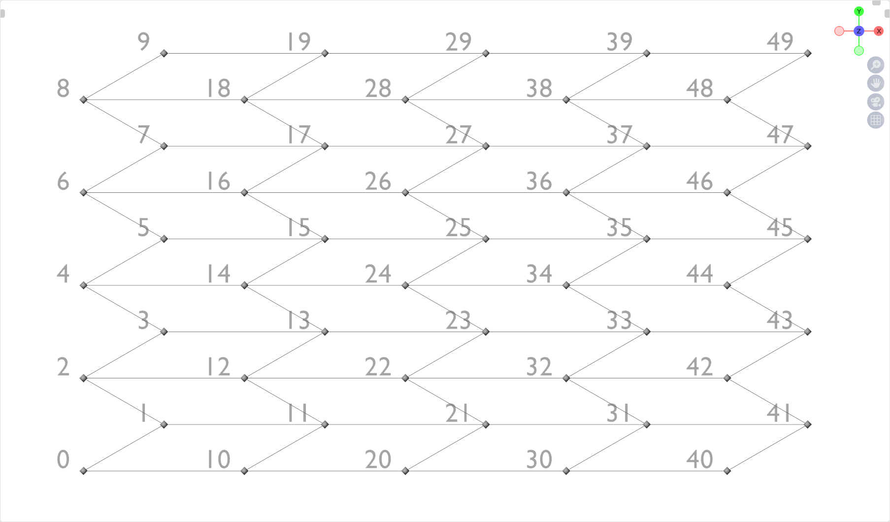
enter image description here

Another slightly modified method is to use a grid to create the necessary points.

Here every second row gets an offset of $1.5$ , which is also based on the calculation of the height of the equilateral triangle.
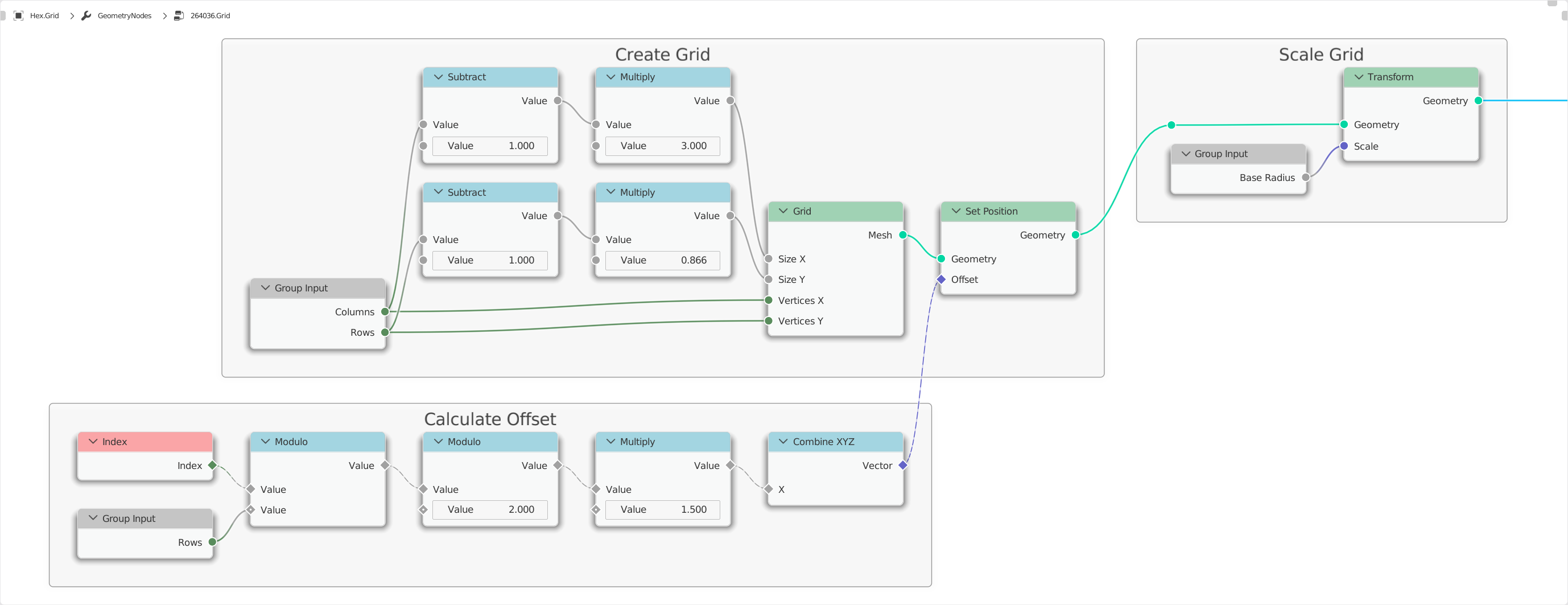
enter image description here


Hexagonal structure with Geometry Nodes - Render 2

All variants presented here can be found in the blend file:


(Blender 3.2)

$\endgroup$
11
$\begingroup$

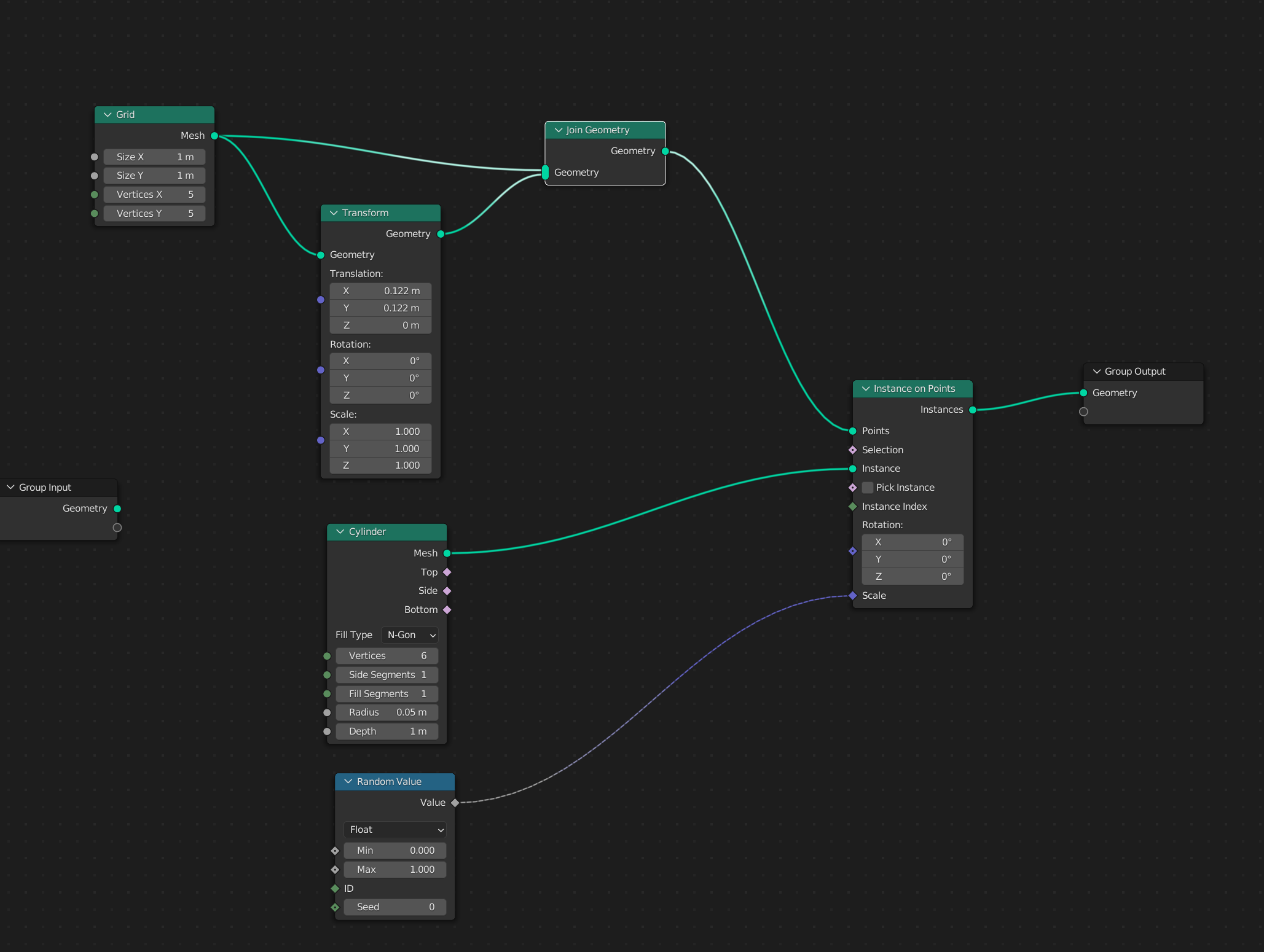
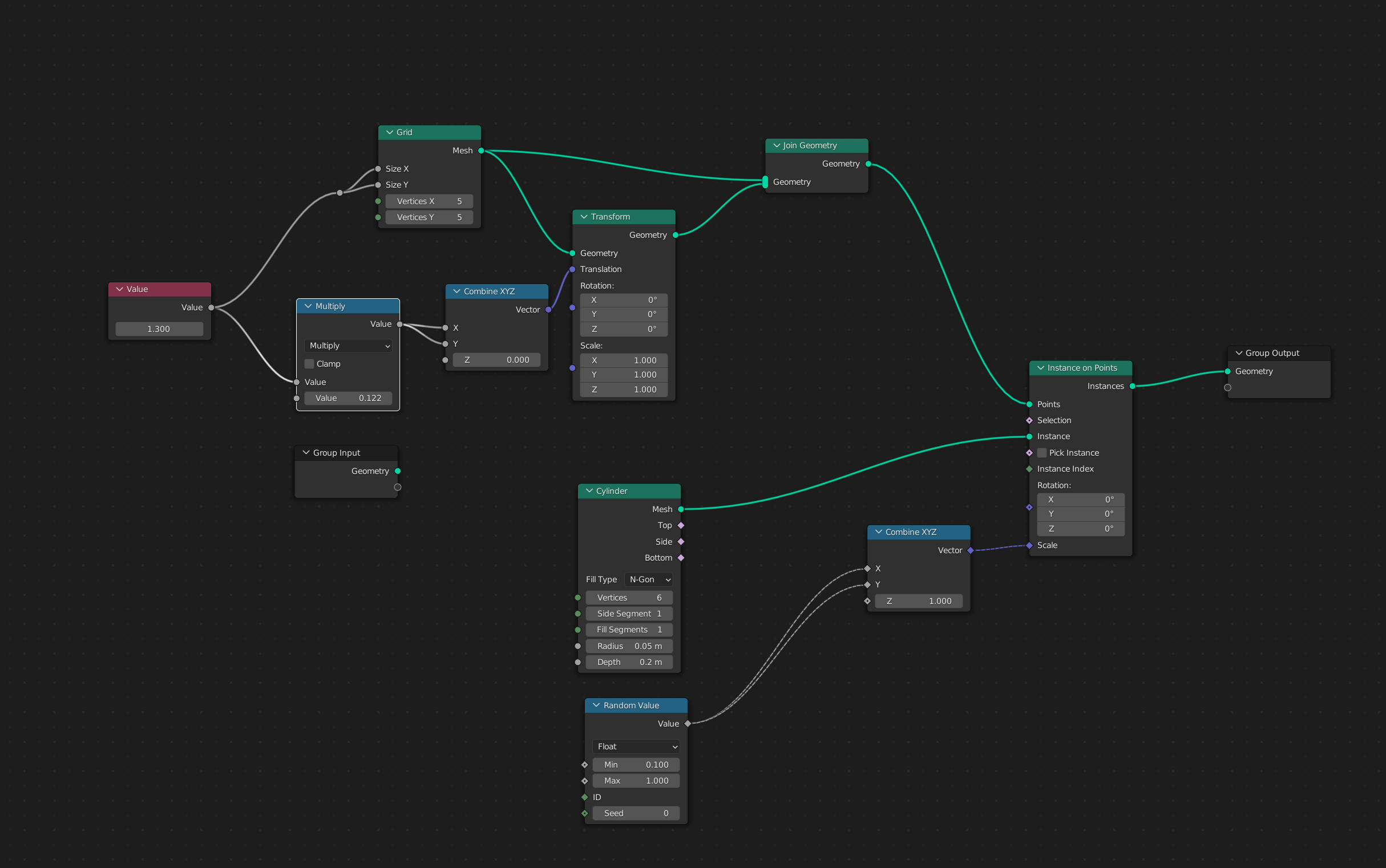
I think this one might be the simplest:

Node group

both in terms of node count, and in ease of explanation:

  1. Create a hex grid.
  2. Populate it with Cylinders with Vertices set to 6 to make them hex shaped.
  3. Assign a random value to the Cylinder Scale.

You need a combine XYZ node that only randomizes X and Y if you want the cylinders all on the same base height.

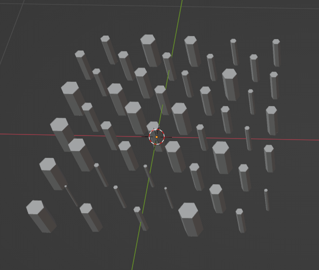
Result

I think that joining two grids that are offset is a bit of a cheat, but it does give you a good hex pattern; and all of this in just six nodes. (7 if you want the cylinder bases at the same height.)

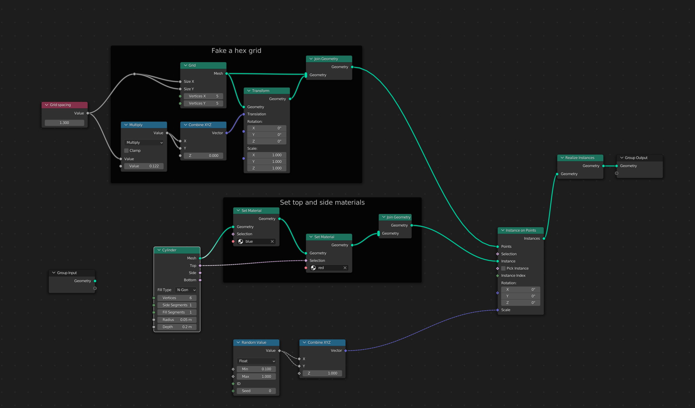
To answer a question in the comments, here's how to parameterize the grid size. Note that this version has the change to support the cylinders all sharing a base height as well.

Node group that parameterizes the Grid spacing

Also note that this group would support the ability to color the sides and tops differently if you added these nodes:

Complete Tree including materials

Thanks to Markus von Broady for the comment correcting my material handling.

$\endgroup$
8
  • $\begingroup$ I have to admit, in terms of the number of nodes, I love this solution the most! I would think that most users would want and expect exactly this simplicity from Geometry Nodes. However, I wonder how you could make the transformation flexible here. How exactly do you come up with 0.122 and how could that remain procedural? $\endgroup$
    – quellenform
    Commented May 19, 2022 at 22:09
  • $\begingroup$ And what I find really cool is that you offset the entire grid here! The only disadvantage would be that the numbering would no longer be continuous, but that is ultimately a question of application. $\endgroup$
    – quellenform
    Commented May 19, 2022 at 22:18
  • $\begingroup$ @quellenform The grid spacing requires that X and Y size are identical and that the X and Y offsets be .122 times that size, so a single Value input feeding both X and Y Size of the grid and feeding a math node that multiplies by .122 and then goes to a combineXYZ that sets both X and Y to that value while leaving Z 0 would make it procedural. $\endgroup$ Commented May 19, 2022 at 22:54
  • 2
    $\begingroup$ Also, .122 was arrived at by remembering that what we do with Blender is create illusions, so I eyeballed the offsets until they worked. (You can derive it mathematically, but I'm too lazy.) $\endgroup$ Commented May 19, 2022 at 22:59
  • 1
    $\begingroup$ This is pretty much the same as a shader answer from 2 years ago! Of course it's the way to go. Dooooooh! :) Drinks on you at the 19th. $\endgroup$
    – Robin Betts
    Commented May 20, 2022 at 17:06
6
$\begingroup$

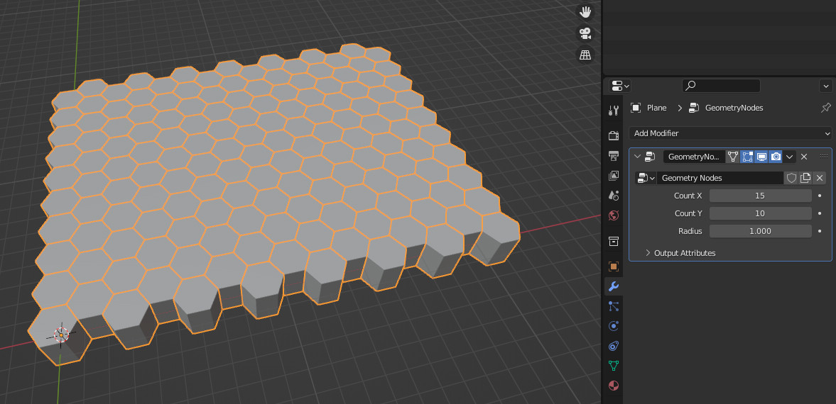
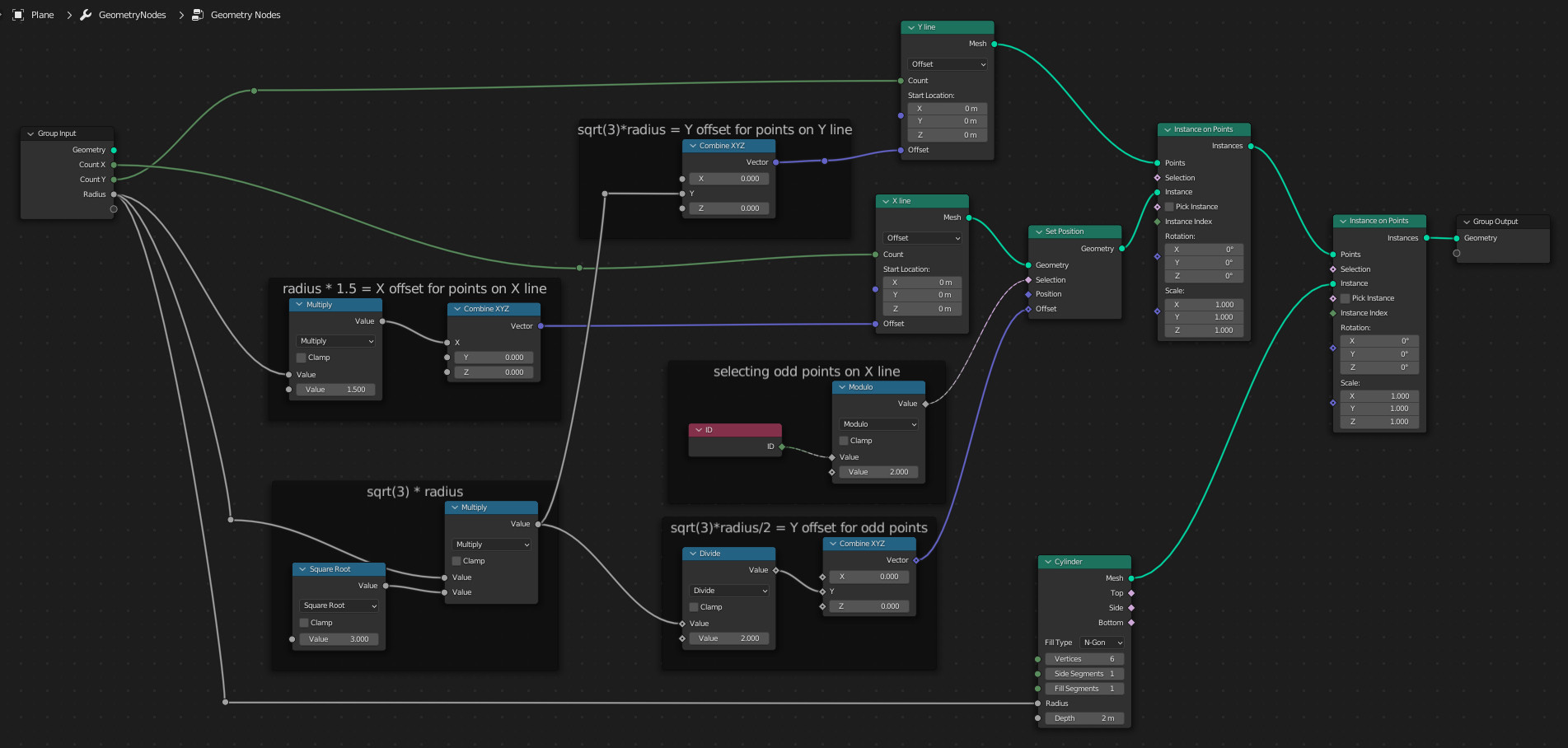
Here is a slight variation on this theme. In my example I create a mesh line in Y direction, with an offset of sqrt(3) * radius between points.

On this line I instance a mesh line in X direction, with an offset of 1.5 * radius between the points. Then I move every odd point by sqrt(3)/2 * radius in Y direction.

The grid of zig zag lines is then used to instance cylinders with 6 vertices and the given radius on each point. After instancing it is of course possible to randomize scale of each instanced cylinder etc. but I didn't implement that just yet, this is only doing the base structure.

Result with input attributes on the Geometry Nodes modifier:

hex grid

The GN nodetree:

nodetree

And the file:

$\endgroup$
1
  • 1
    $\begingroup$ Thank you for this solution! Short and sweet! $\endgroup$
    – quellenform
    Commented May 19, 2022 at 16:49
6
$\begingroup$

Crikey.. playing node golf with you guys, I'm not going to make the cut. :(

Mine was the grid approach, too..

enter image description here

..only difference, (after setting it to dimensions adapted from input) was using its points with a checker select:

enter image description here

and trying to make a more-or-less reusable group from it, which is then used outside, in a second modifier, to reach @quellenform's specs:

enter image description here

enter image description here

$\endgroup$
1
  • $\begingroup$ I love to play node golf with you ;-) $\endgroup$
    – quellenform
    Commented May 19, 2022 at 16:38
6
$\begingroup$

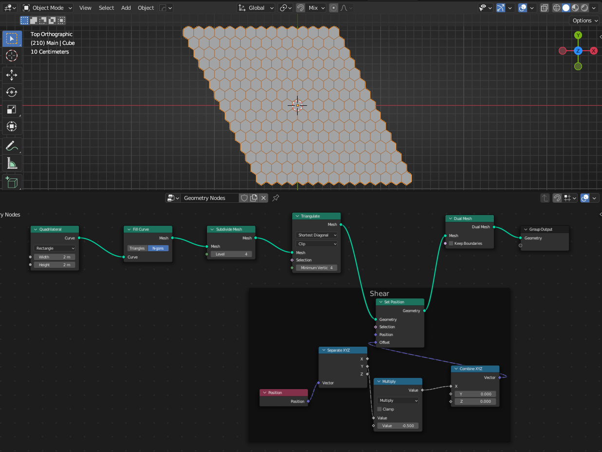
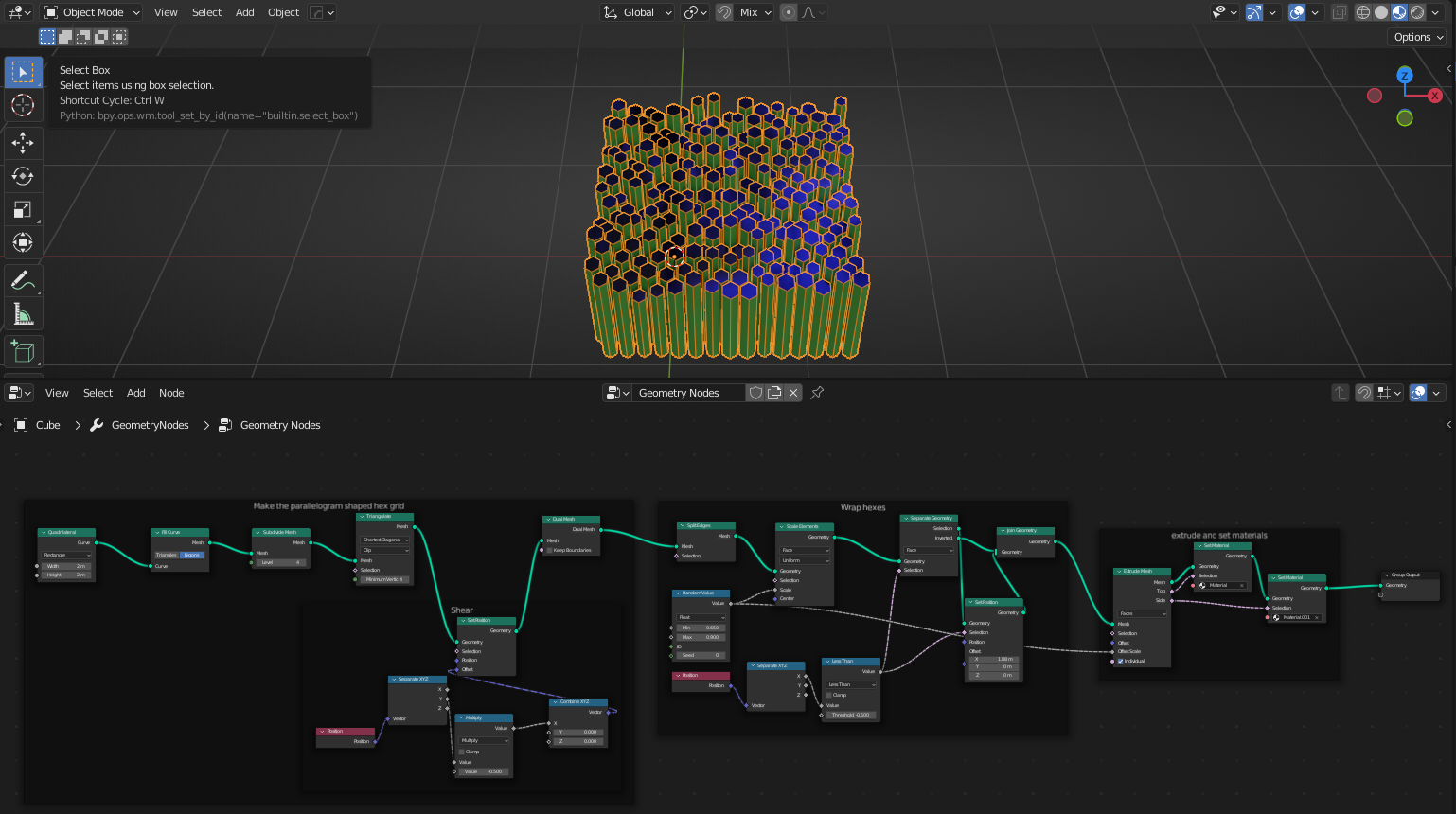
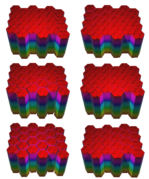
Using a plane which is subdivided and triangulated and then fed through dual mesh produces something which is close, but not quite as neat. You'd need to clip off the excess sides, but I was surprised by how close this got and how simple the node tree was: dual mesh and shear

However, if you then add nodes to separate out the hexagons and position them appropriately, you can rapidly get something very useful, with the benefit that none of it requires ANY complex maths. There's a magic number in there which should probably be based on the size of the model instead, but in general if you don't want to be calculating anything and just doing it by eye this approach might be a good one to take.

Final output

Blend File

(Unsure why this blend file is reported as not a blend by the typical upload locations. Tried both, didn't work)

$\endgroup$
3
  • $\begingroup$ I really like this one. I knew there would be a dual somewhere, and couldn't find it! Is it easier to break your shear into a rotation followed by a scale? See here for a possibility... $\endgroup$
    – Robin Betts
    Commented May 19, 2022 at 17:17
  • 1
    $\begingroup$ @RobinBetts yes that's probably a much better way of doing things. It requires actual maths though, rather than -0.5 and 1.875 and I found those numbers by just changing the boxes in incrementally small amounts :) $\endgroup$
    – Ben
    Commented May 19, 2022 at 17:23
  • $\begingroup$ After your update, I can now see what you meant. Well done, I like the approach that solves this without any math, I like it! $\endgroup$
    – quellenform
    Commented May 19, 2022 at 17:40
1
$\begingroup$

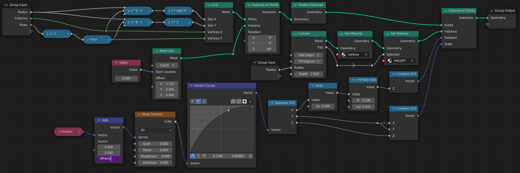
Given an assumption of an even number of rows (could be fixed by deleting the last row of vertices at one point), I came up with this setup:

The Vector Curves node combines a color ramp functionality controlling how likely the cylinders are to touch (with unaltered noise they never touched, though forcing them to made them unhappy), and a map range node controlling the maximum cylinder height.

Keep in mind you don't actually need two materials to control the top, you could control the distinction inside the shader, thanks to which the renderer wouldn't need to duplicate vertices on material edges...

$\endgroup$
3
  • 1
    $\begingroup$ Magic numbers legend: 1.732 - sqrt(3). 5.236 and 0.524 - as in the node title, it's radians(60*5) and radians(30) - the times 5 multiplier is the reciprocal of the snap value .2, which was taken arbitrarily (should probably be 1/6) $\endgroup$ Commented May 20, 2022 at 0:09
  • $\begingroup$ I decided not to control the distinction inside the shader, because that means by shaders only have 4 nodes between the two of them and I don't have to worry about someone rotating the whole thing. Maybe that was too simple? $\endgroup$ Commented May 20, 2022 at 0:21
  • 1
    $\begingroup$ @MartyFouts I also don't separate the top from the sides in the shader because OP asked for separate materials, but in my case since those are instances, the local Z of the instance remains unchanged and therefore you can easily distinguish the top by normal. $\endgroup$ Commented May 20, 2022 at 0:25

You must log in to answer this question.

Not the answer you're looking for? Browse other questions tagged .