4
$\begingroup$

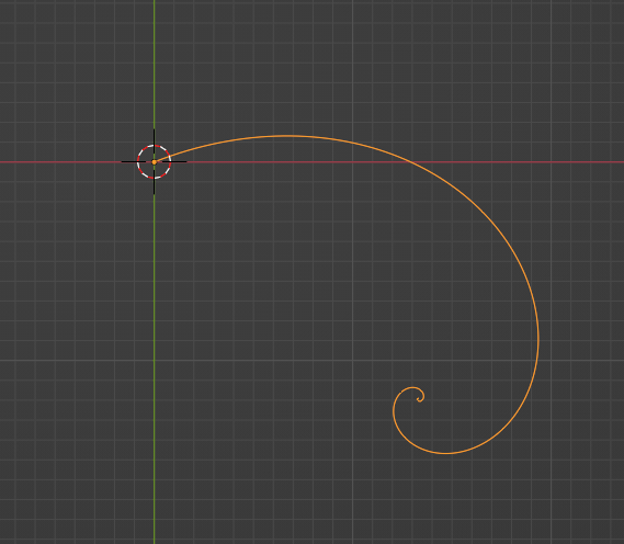
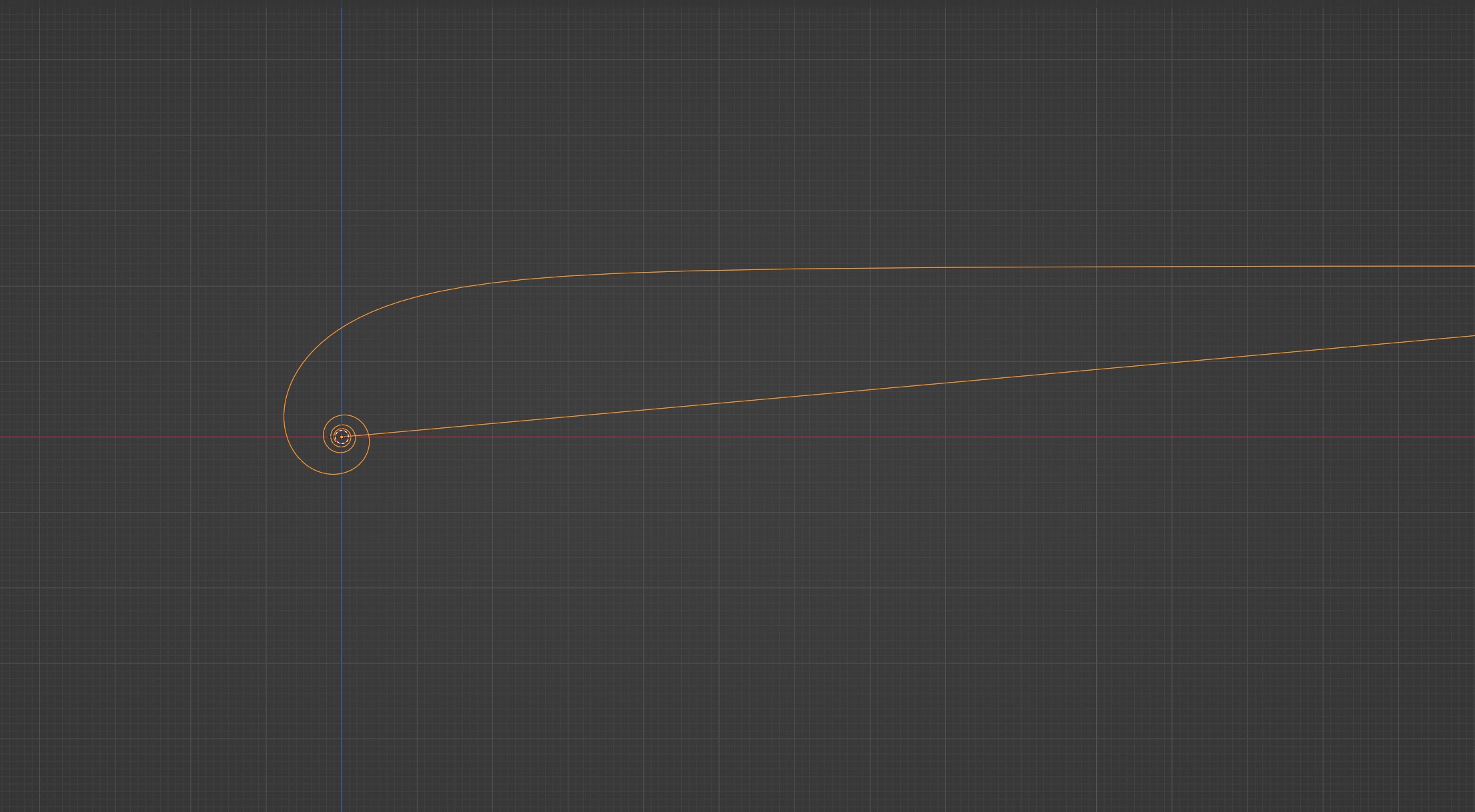
I'm trying to curl a line via GeoNodes. See here: Spiral wanted result

As you can see, the line stays fixed at its origin and then curls according to an angle/curvature parameter. The length along the curve stays constant.

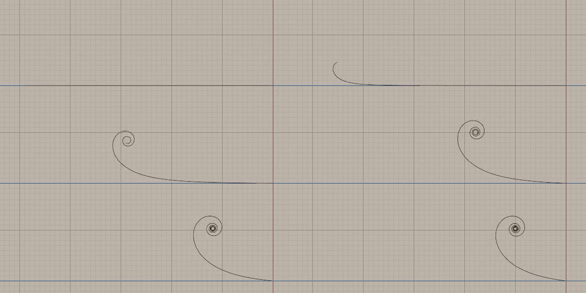
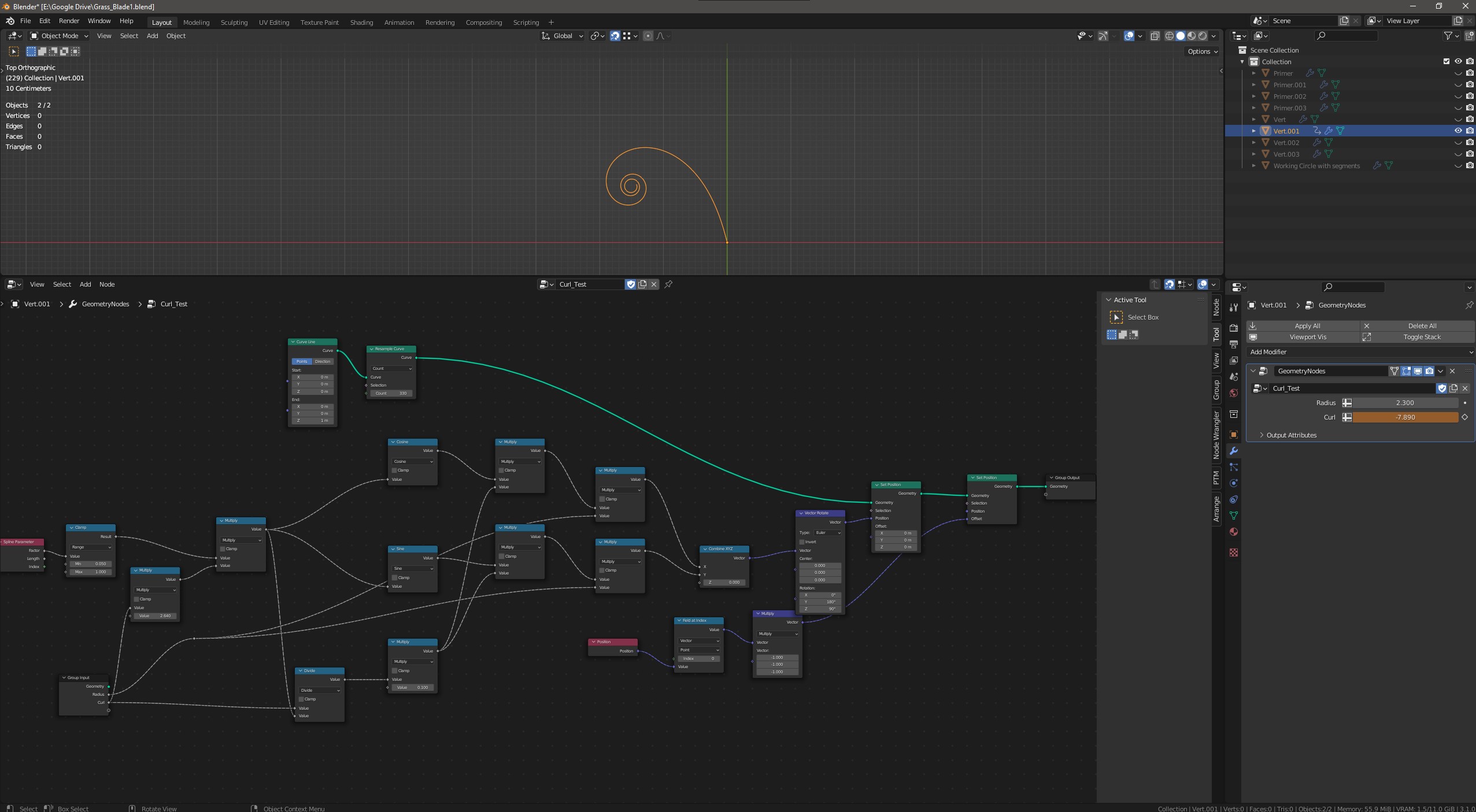
I managed to create a setup that basically creates the right shape (in terms of curvature), but length and offset are off and generally it's not working correctly. The spiral's center should not be fixed at the origin, but rather be transcendent according to the curvature. Image of NodeTree result
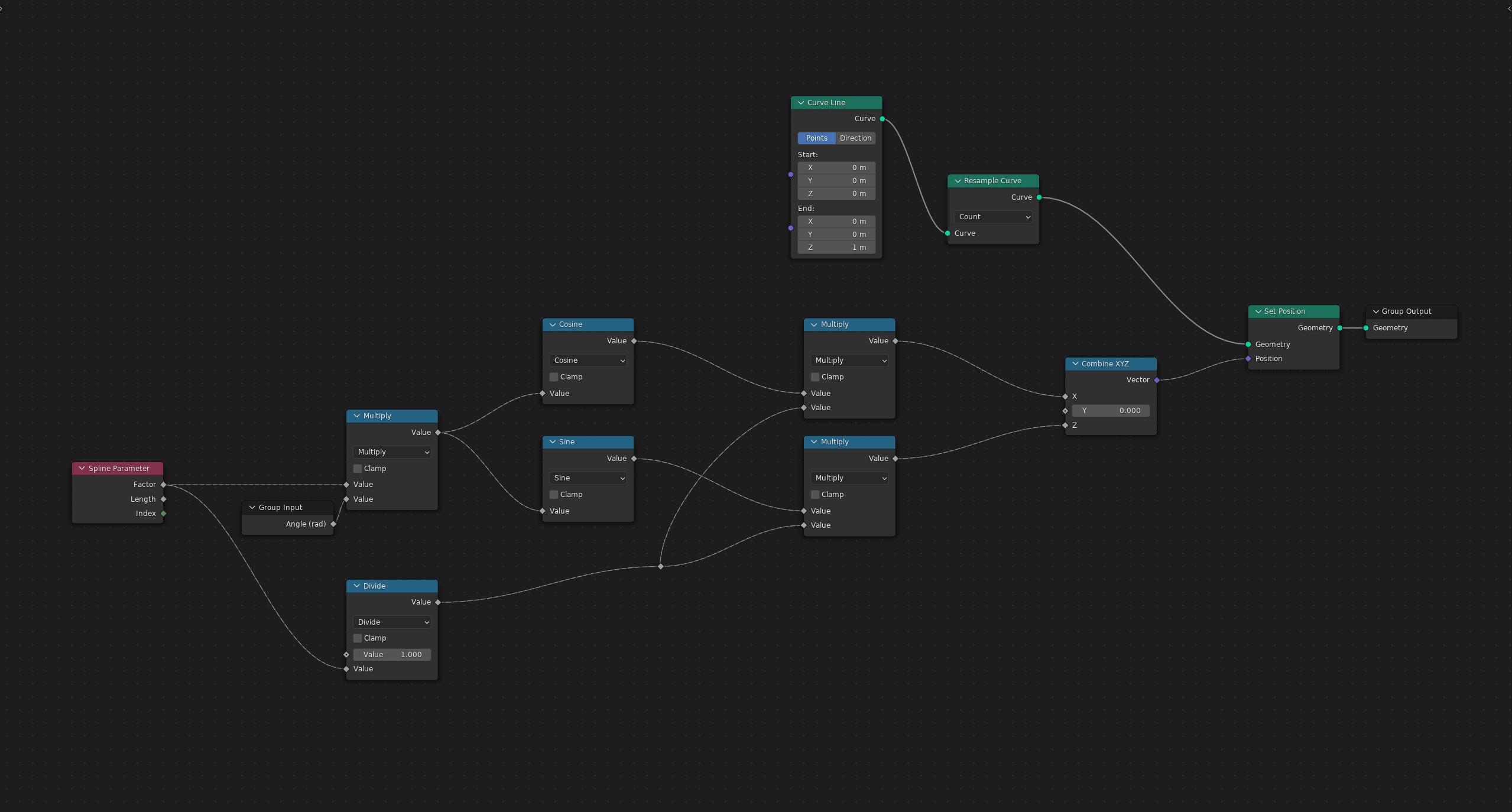
This is my node Tree: enter image description here

I already tried a vast amount of combinations, but no success. I also read a lot about spirals, but couldn't find any information about how to create a spiral "from the opposite end". And now I'm not even sure if it has to do with spirals at all or if I'd rather call it "circular interpolation". :)

So, is this even the right approach? Any hints into the right direction are highly welcome!

$\endgroup$
0

3 Answers 3

3
$\begingroup$

Your question is more of a math question and I can't answer that (and you might be better off asking it over at math.stackexchange), but if you would be satisfied with only achieving the visual result, that's easy enough (though, not the "curve length stays constant" part):

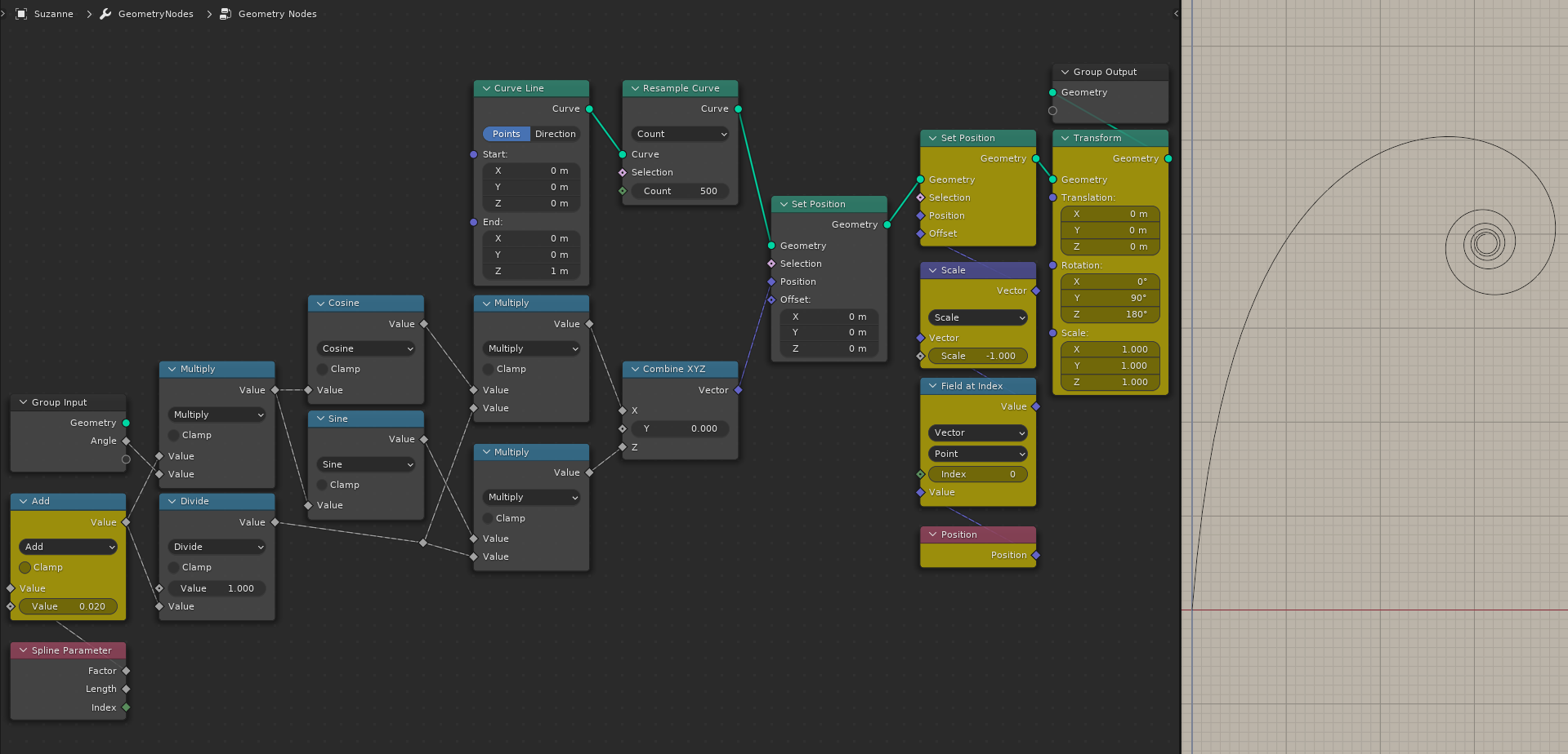
enter image description here

I marked my additions to your setup with yellow. First Add node is to get rid of that long line you have going from the origin point to the end of the spiral (well, technically, the start). I don't know much about math, but I assume that's happening because Spline Parameter—Factor gives you a linear gradient of floats from $0$ to $1$ and since $\frac{1}{0}$ is undefined, it just puts the first point of the curve to $0,0,0$. Adding a very small number get rids of that. Closer to $0$ that number is, longer the "stem".

Second group of nodes simply uses the Position of that point at the end of the stem (Index0) to offset the whole group in the opposite direction, then rotates it so it stays upwards and looks to right.


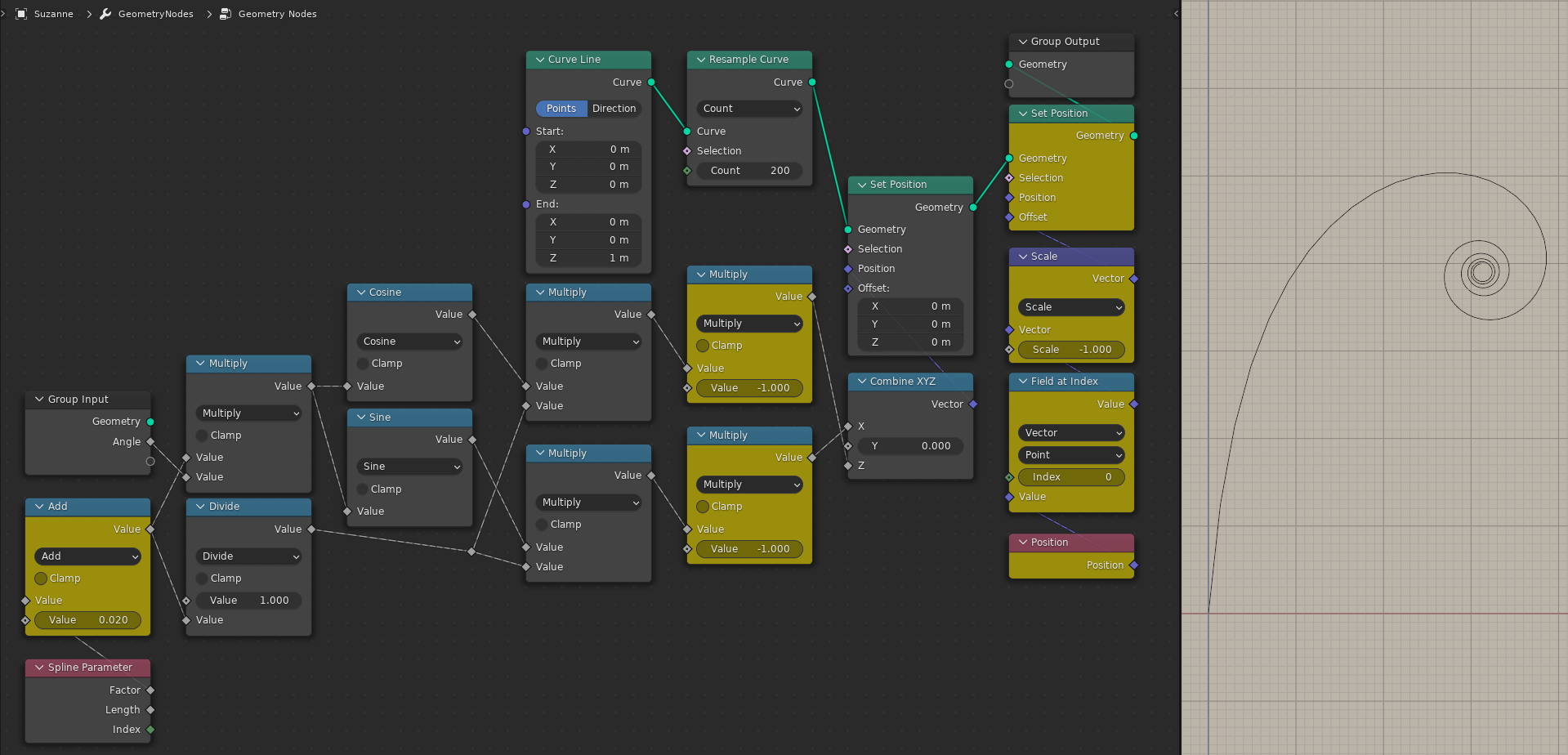
Edit 1: Instead of the Transform node for rotation, you could simply switch the X and Y values of your setup and make them negative:

enter image description here


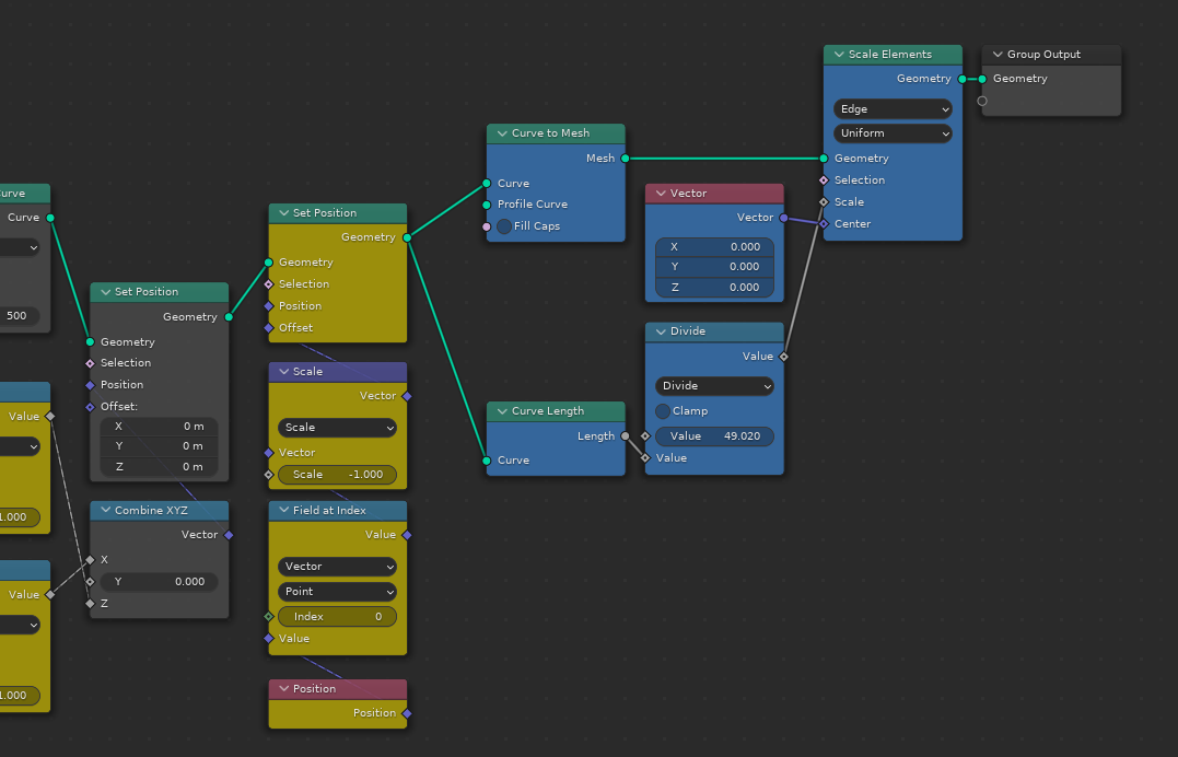
Edit 2: Here's a super hacky way of making the curve retain its length:

enter image description here

Marked the newly added nodes with blue. I'm taking the length of the curve at the animation start when it's just a vertical line and scaling the result down in proportion to it. The magical $49.020$ number happens to be the length of the curve when the rotation angle is at $0.000$ and the first Add node value is at $0.020$. If you wanted to change that number to adjust the length of the "stem", you would need to hook up a Viewer node to the curve before scaling (with rotation at $0$) to see the new curve length in the spreadsheet and put that into the Divide node.

$\endgroup$
2
$\begingroup$

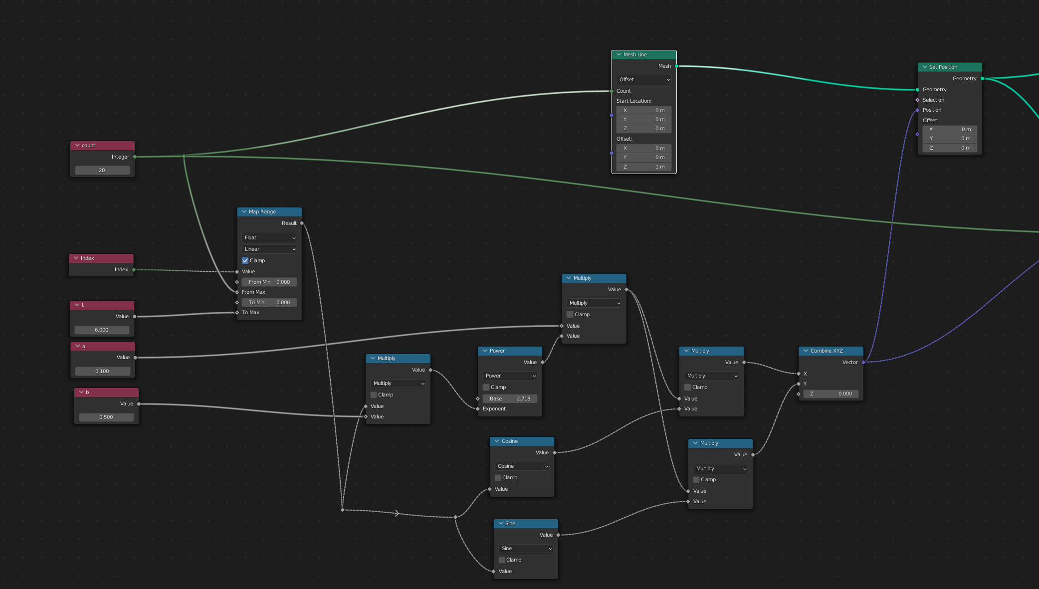
The curve you're trying to produce is called an "Equiangular spiral". Since Blender operates easily in Cartesian coordinates, here's one way to do it with parametric equations: $$ x(t) = ae^{bt} * cos(t)$$ $$ y(t) = ae^{bt} * sin(t)$$

Where $a$ and $b$ are constants.

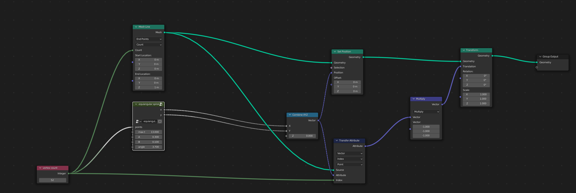
The easiest way to generate a curve from parametric equations is start with a mesh line; compute the equations; and then use a Set Position node to adjust the points on the mesh line. Here's part of a Geometry node tree that does that:

calculating a spiral

Note that I use several Input nodes, labeled to show the constants $a$ and $b$ as well as a count of line segments. The more line segments the smoother the curve.

Note also that a Map Range node is used to set the range of t from 0 to some maximum value. That will give you the number of turns.

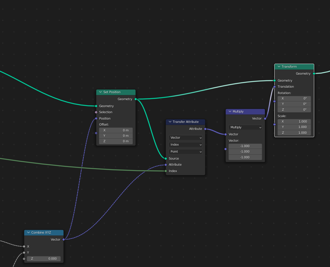
The problem with this node group, as you've found out, is that it places the "wrong" end of the spiral at the origin. Here's a technique for moving the spiral so that the other end is at the origin:

Translating the spiral

This uses a transfer attribute node to obtain the location of the endpoint of the mesh. It then multiplies the coordinates by -1, and uses them as the translation input for a Transform node. This effectively subtracts that value from every point on the line, moving it to the origin.

What is not shown is the technique for rotating the curve to obtain the final alignment you desire. To do that, simply add a constant to T in the trig functions, resulting in that much extra rotation:

$$ x(t) = ae^{bt} * cos(t+\theta)$$ $$ y(t) = ae^{bt} * sin(t+\theta)$$

example output

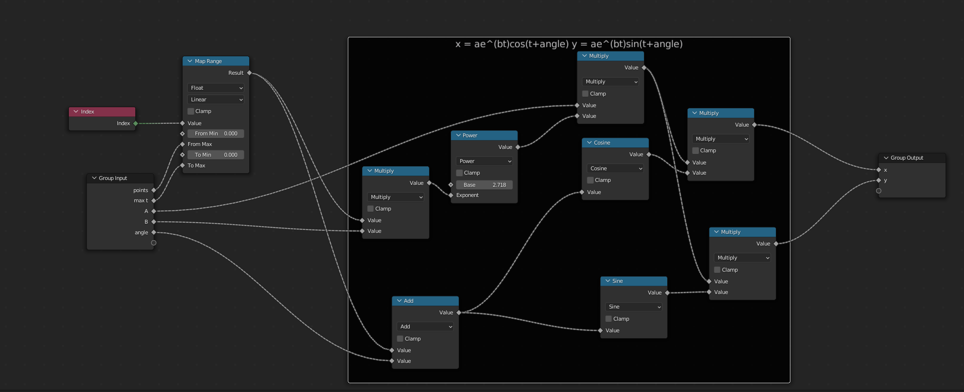
Here's a version with the math cleaned up into a node group, showing the full tree:

full tree

math node group

$\endgroup$
1
$\begingroup$

Although good answers here which work to a degree, I came up with another solution. I thought I was going for a spiral, but actually that wasn't my goal in the end. More on that below.

Regarding the spiral equation, there are multiple solutions possible with GeoNodes. Even for hyperbolic spirals there are at lest two ways build them. But in the end, I guess most spiral node setups have different (dis)-advantages. In addition to that, there are numerous different types of spirals.

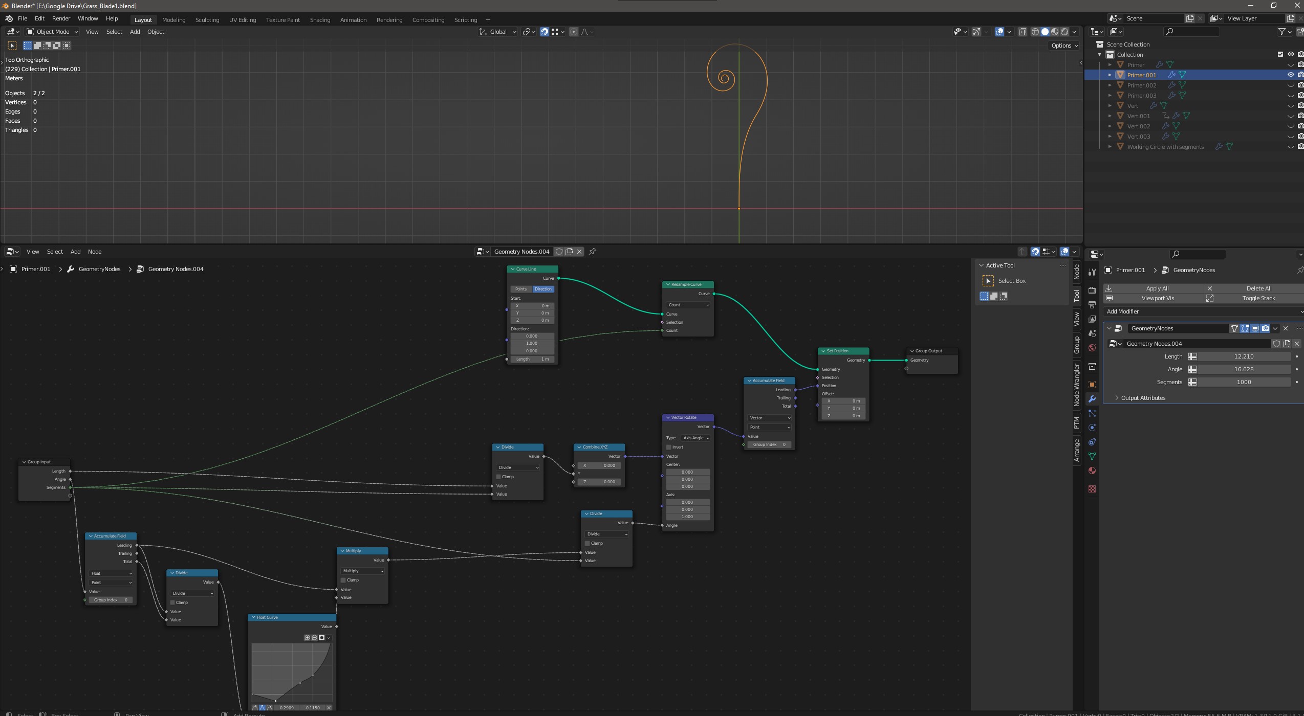
So it turned out that I didn't want to build a spiral per se, but rather a line segment which iteratively deforms in a circular manner, driven by a 2D-Curve. Here's the setup that also allows to "bend" segments. With a linear curve applied, I get the former desired spiral shape:

enter image description here

To additionally answer the initial question: Kuboa gave the right hint to correctly orient the spiral. Here's my first solution:

enter image description here

$\endgroup$

You must log in to answer this question.

Not the answer you're looking for? Browse other questions tagged .