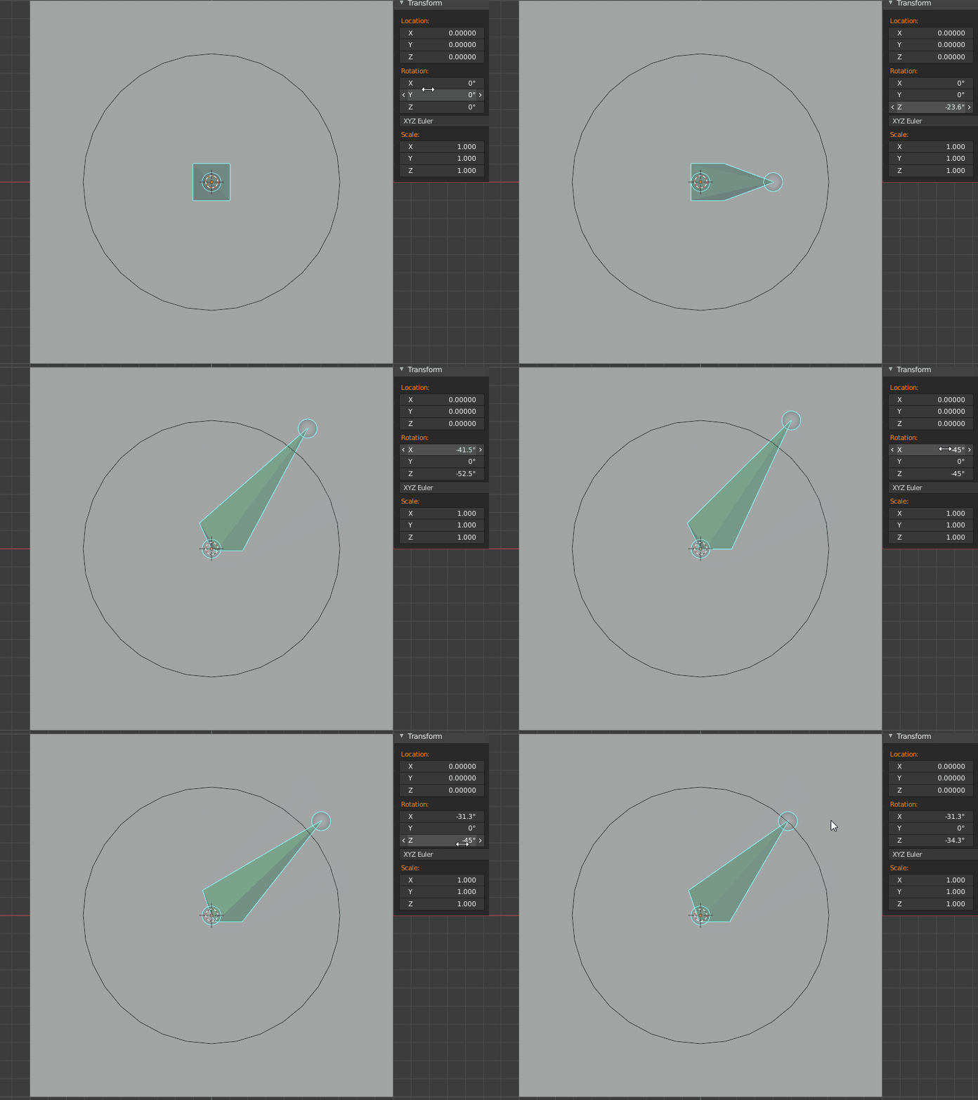
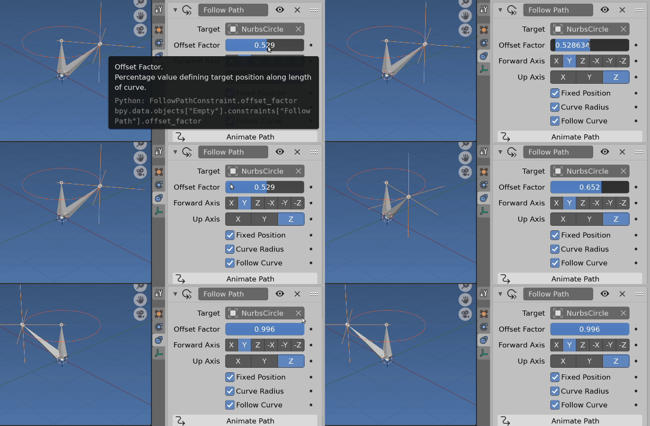
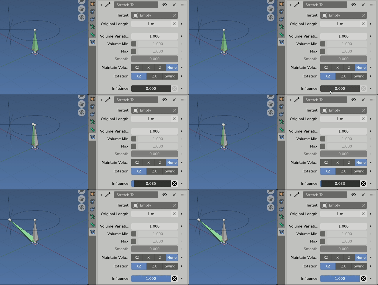
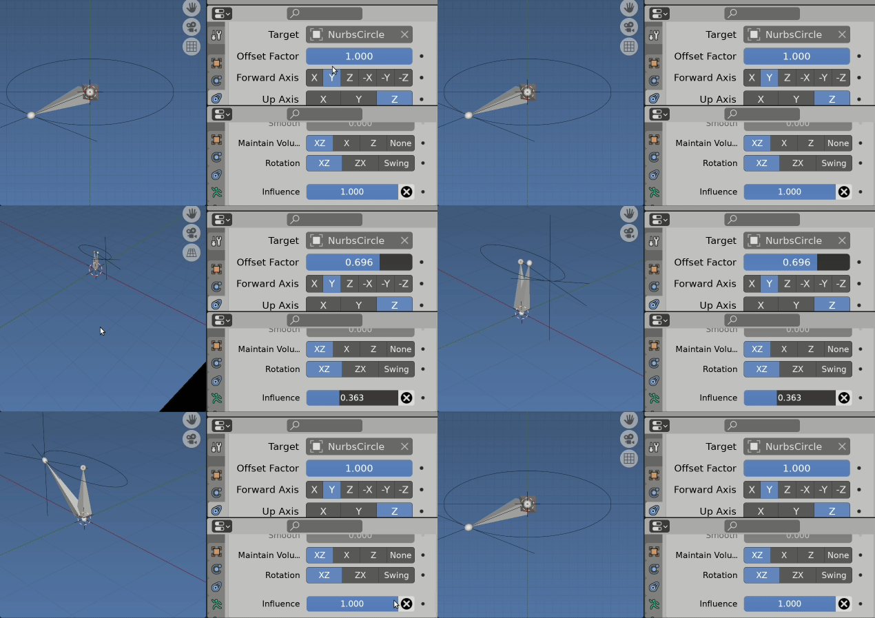
A limit rotation constraint is never going to be very good for this, because 1) there isn't really any such thing as 3D rotation in 2 simultaneous axes; and 2) the nature of Eulers and aliasing means that even if you're careful about your angles, the angles you input are not necessarily going to be the angles that get limited. (Think about how 180, 0, 0 is the same orientation as 0, 180, 180 and it becomes more clear that there is more than one way to reach any particular orientation, so Blender just picks one, which isn't necessarily the one you want.)
There are other techniques for what you want here-- for example, if you damped track a marker with a floor + limit distance (inside) constraint, you can constrain the rotation to a particular circle. Or, you could do a single-bone IK, locked in Z and limited only in X, leaving the Y free.
But for you, especially since you're interested in non-circular shapes, I'd do it with a shrinkwrap constraint setup:
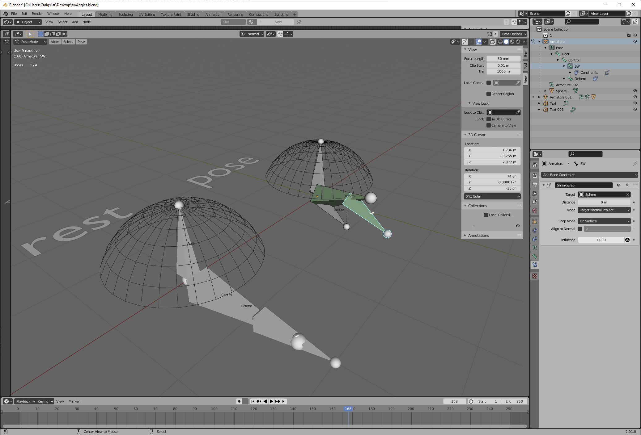
We start with a "root" bone (which, for an eye, would be your head bone). The angle limits are actually defined by a mesh-- here, a slightly edited UV sphere. This angle-limiting mesh is parented (bone relative) to the root bone. Obviously, you want it disabled in renders, and perhaps shuffled off to some collection full of control doodads that you don't want to always have to look at.
The control bone is parented to the root bone. The control bone has a child bone, SW, which has a shrinkwrap constraint targeting our mesh object. (Setting this to "target normal" mode, and our mesh object to smooth shaded, will help interpolation.) Then finally, our deform bone, which is parented to the control bone, damped tracks the SW bone. That lets us define our angle limits with any arbitrary mesh we want. Where can the bone point? Wherever there's something for the SW bone to shrinkwrap to.
Notes:
Meshes are actually made out of flat faces of course. Your interpolation and the extent to which your mesh actually represents a circle depend on its vert density. Feel free to give the angle-limiting mesh a few levels of subdivision. Because it will never get any other modifiers, and is bone parented, that subdivision only ever has to be calculated once; and shrinkwrapping a single point to a target, even a very high vert count target, is fast-- I haven't been able to make enough verts to notice any slowdown from a shrinkwrap constraint :)
A sphere, centered on Control, with the same radius as the length of Control, means that SW won't ever much move closer or further than control. But try it with a circle instead, and see how the difference in shape changes the interpolation from on edge to the other. This can be useful, but the main thing is to just know that it exists.
Obviously, feel free to change the shape of your angle-limiting mesh any way you'd like. Starting with a sphere, cutting it with a knife operation, and then deleting one side lets you define the angle limits with your knife operation.


