2
$\begingroup$

Dust collection adapter

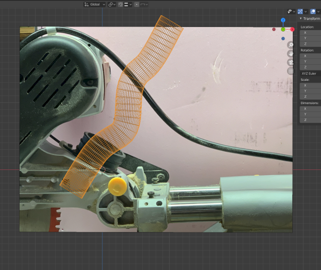
I have tried to follow other answers to similar questions posted with no success. I'm using Blender 2.83. I am trying to create an adapter for my miter saw for dust collection, which I will be 3D printing. So I need specific dimension for my model which also cannot use shading or smoothing as they do not translate to the 3D slicer .stl file I will be exporting.

I need a pipe with the following (all measurements are in mm):

  1. Radius of pipe is 29.2142mm
  2. Both ends must have a straight section for 20mm
  3. It must have two 30 deg angles so the adapter will offset around the motor on the saw as shown in the picture
  4. The pipe should have 100 vertices when created to make the circle as round/smooth as possible (I was not sure how to set this using the Bezier Circle and Curve method for creating the pipe). This is where shading and smoothing would not work.

Would appreciate step by step help anyone will provide.

$\endgroup$
4
  • 2
    $\begingroup$ You can use a curve with bevel, convert it to mesh and smooth it with Subdivision Surface modifier to increase the resolution to a lot higher than 100 vertices around if that helps. $\endgroup$ Commented Jun 24, 2020 at 15:52
  • $\begingroup$ What's the actual tolerance you're looking for? 1/10 of a micron seems unlikely.. ? Would it be possible, at the critical joint, to make it slightly small, and, in one way or another, bore it back to size? $\endgroup$
    – Robin Betts
    Commented Jun 24, 2020 at 15:56
  • $\begingroup$ I took the dimensions off another connector I’ve already made, which fits the opening just perfect. I just need the pipe to bend around the motor. So setting the specs to the other should give me what I need $\endgroup$
    – Claus
    Commented Jun 24, 2020 at 16:54
  • $\begingroup$ Martynas Žiemys tried your suggestions. You did not provide enough instructions for me to make it work. So not sure how I would construct the pipe from that. Can you lay it out step by step? $\endgroup$
    – Claus
    Commented Jun 25, 2020 at 21:22

2 Answers 2

2
$\begingroup$

To create a precision model suitable for 3D printing here is how I finally solved the puzzle that enabled me to enter the exact dimensions and angles needed for the part. If you know all the key strokes, you only need to read the first sentence in each item. The remainder are just step by step keystrokes for those not familiar with navigating around Blender

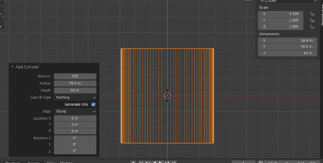
  1. Add mesh cylinder – and set the following
  • A) Vertices = 100 B) Radius = 29.2142
  • C) Depth = 60 mm
  • D) Fill Type = Nothing
  • E) After other setting are made scale it. Ctrl + A > Scale

enter image description here

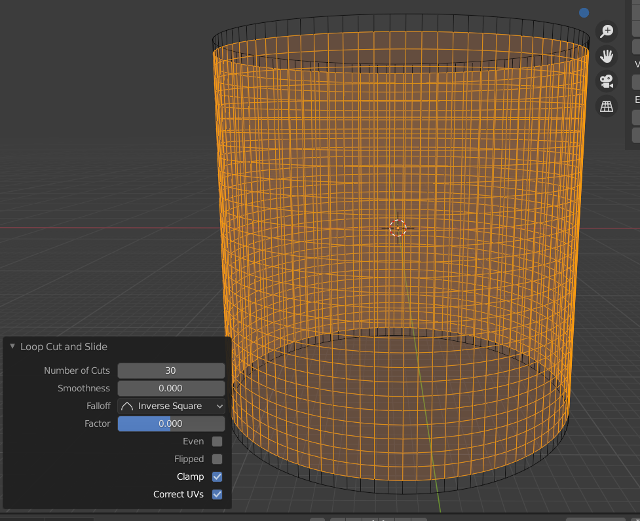
  1. Add 30 loop cuts (one for each degree) for bending the pipe as follows
  • A) Tab into edit mode
  • B) Ctrl + R, Left Click, Right Click
  • C) Enter 30 in Number of Cuts enter image description here
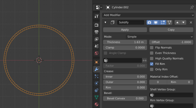
  1. Add Solidify modifier to cylinder wall
  • A) Switch to top view press Numpad 7
  • B) Click the modify tab “wrench icon”
  • C) Click Add Modifier and select Solidify
  • D) Change Thickness to 1.63mm
  • E) Check Even Thickness and High Quality Normals (note - picture does not show these two checked, but it is needed to make both inside and outside walls even)
  • F) To add to inside wall leave offset at -1. To add to outside wall change to 1 G) Click Apply enter image description here
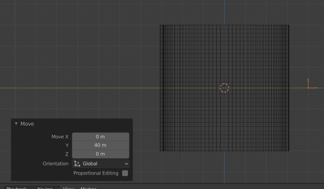
  1. Add an empty to use as an axis point for bending the pipe
  • A) Shift + A – add empty, use type with arrows easier to see orientation of empty.
  • B) Scale it up a bit so it is easier to see
  • C) Move it on the Y axis about 40 mm
  • D) Both the cylinder origin and the empty should be on the Y baseline enter image description here
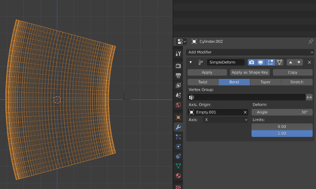
  1. Add Simple Deform modifier to cylinder
  • A) Select cylinder
  • B) Click Add Modifier and select Simple Deform
  • C) Select Bend
  • D) In Axis, Origin select the empty you added in step 4
  • E) Change angle to 30 degrees
  • F) Click Apply (Important for the next step) enter image description here
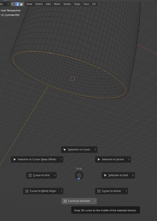
  1. Change origin of pipe to the bottom
  • A) Tab into edit mode
  • B) Change to Edge Select mode
  • C) Select either inner or outer bottom edge. Hold cursor over edge and press Shift + Alt to select the complete circle
  • D) Move cursor to selected by pressing Shift + S and choose Cursor to Selected
  • E) Tab into object mode
  • F) Click Object and select Set Origin / Origin to 3D Cursor
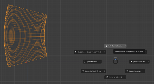
  • G) Move cursor to World Origin, Shift + S to World Origin
  • H) Then move pipe to 3D Cursor, Shift + S Selection to Cursor enter image description here enter image description here
  1. Set pipe flat on base line
  • A) Change view to Right Orthographic view by clicking numpad 3 pad
  • B) Turn on Snapping, make sure Increment is selected and the magnet icon is highlighted. Or with cursor in viewport open the property settings menu and type N
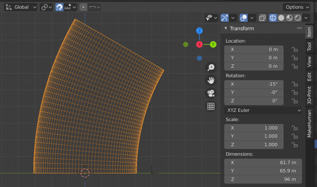
  • C) Rotate the pipe on the X axis -15 deg. Either typing -15 in Rotation X or in the viewport, type R then rotate pipe with mouse until it snaps to the y axis enter image description here
  1. Extrude top faces of pipe 20mm
  • A) Tab to Edit mode
  • B) Change view to solid mode
  • C) Select Face mode
  • D) With cursor over a top face select all with Shift-Click
  • E) With top faces selected type E to extrude and 20 for 20mm enter image description here
  1. Duplicate pipe and rotate
  • A) Tab to object mode
  • B) Change to wireframe and X-ray mode
  • C) Switch to Right Orthographic view, click Numpad 3
  • D) Duplicate pipe with Shit+D and Enter
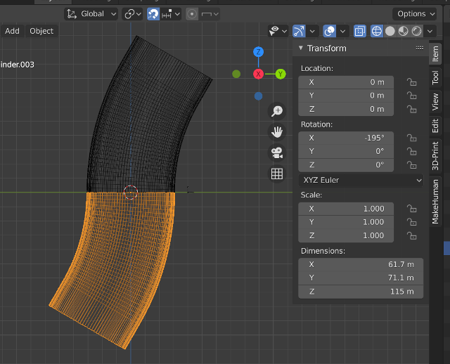
  • E) The new pipe needs to be rotated 180 deg on X axis, BUT it is already sitting at a -15 deg angle. You can either enter -195 in the items property settings or with snap to grid still activated hold down Ctrl while rotating pipe with mouse until it snaps in place so both pipe sections match up exactly. enter image description here
  1. Prepare both pipes to be joined into one object by removing bottom faces from both pipes before joining
    1. Switch to solid mode
    1. Press H to hide bottom pipe temporarily
    1. Select top pipe and Tab into edit mode
    1. Select bottom faces as described earlier
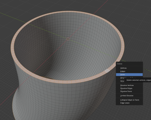
    1. Press X and select Delete Faces
    1. Tab back into Object mode
    1. Press Alt+H to reveal bottom pipe
    1. Make sure only the top pipe is selected press H to hide
    1. Then repeat these steps for the bottom pipe for the edge that will be joined to the top pipe enter image description here
  1. Next join both pipes with a simple Join Ctrl+J
  • A) Switch to wireframe and X-ray mode
  • B) Select both pipes
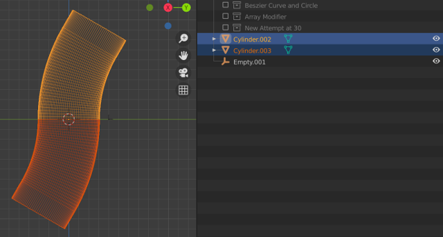
  • C) Click Ctrl+J to join the two pipes. enter image description here
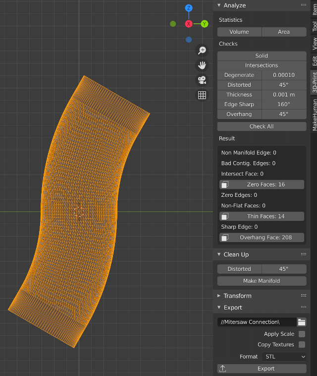
  1. Verify the final pipe can be 3D printed. This can most easily be done if the 3D-Print add-on has been installed in preferences. The main thing is the final object cannot have non-manifolded edges. But since The posted questions really does not speak to this issue, I will not cover it in detail other than to say since the final object has to be printed, the dimensions have to be accurate or else the part would be useless enter image description here
$\endgroup$
0
$\begingroup$

I apologize if this is a little basic/simplistic, but I thought I'd keep it simple since I don't know your level of skill with Blender (I'm beginner/intermediate myself).

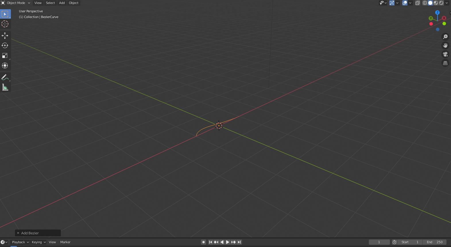
I would start with a Bezier curve, place it at 0,0,0 and start in the X direction (Y,Z = 0) and rotate the image of the miter saw to match that. Any time I've tried using a curve that didn't start out exactly following one of the axes, it just didn't work right.
enter image description here

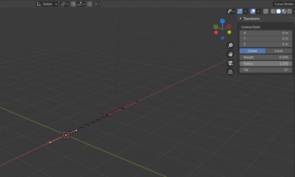
You'll notice that the origin of the curve is at 0,0,0 but the curve actually starts at X = -1. Go into edit mode, select the rear point, and move it to 0,0,0. Select one of the handles for that point and change the Y value to 0, that will adjust the curve so it lines up along the X axis.
enter image description here

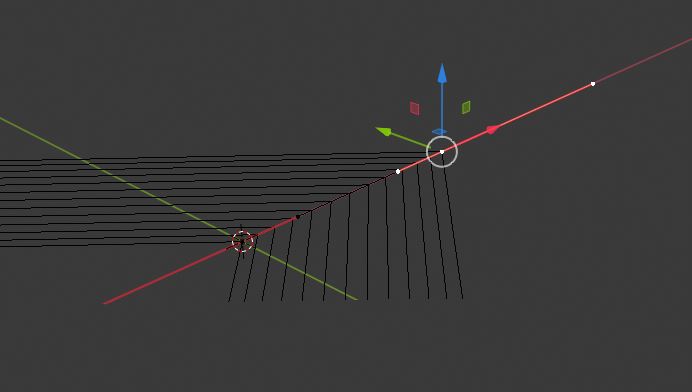
Move the forward point until it's 20cm away and adjust the handles so they don't overlap (this just makes it easier to see what you're doing). You'll have to zoom in pretty close for this part.
enter image description here

With the middle of the front point selected, hit e to extrude, hit x to lock to the x axis, and drag the new point a little distance away. Do this four more times to get all of the points you need; the last point should be at the end of where you want the pipe and the point before that should be 20cm before that.
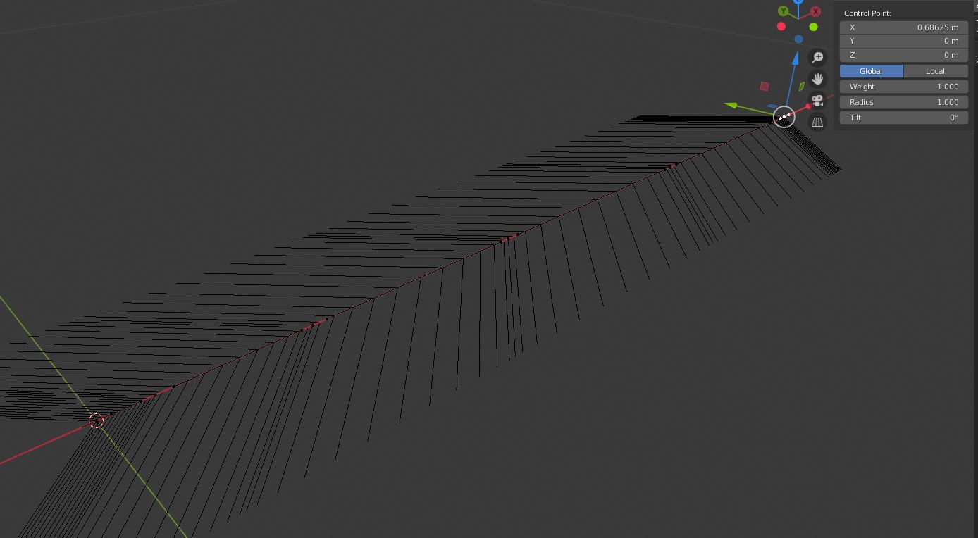
enter image description here

Looking along the X axis from the start, rotate the 3rd and 5th points by 30 degrees (hit Z to lock to the Z axis).
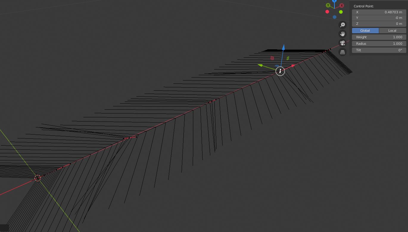
enter image description here

Switch the transform orientation to Normal and move the 3rd and 5th points until the bend looks decent. Exact amount isn't important at this point, you can fine tune it later. Take the middle point (#4) and move it along the Y axis to get the bend.
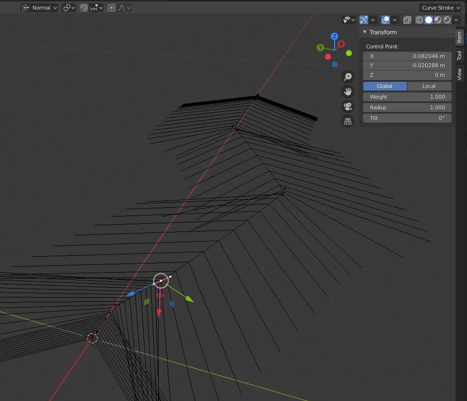
enter image description here

You can also use the end points (keep transforming around the Normal axis) to smooth the curve; again, this will be fine-tuned a little later.
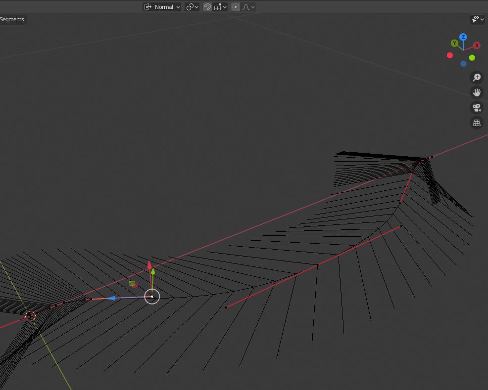
enter image description here

Next, add a cylinder (make sure you tab back to Object mode!) with 100 vertices and the radius you want. It comes with a length of 2 meters, you'll want to lower that to make it easier to work with but I'd recommend starting with an even number, maybe 0.05 meters. Add a 90 degree rotation so it's oriented along the curve.
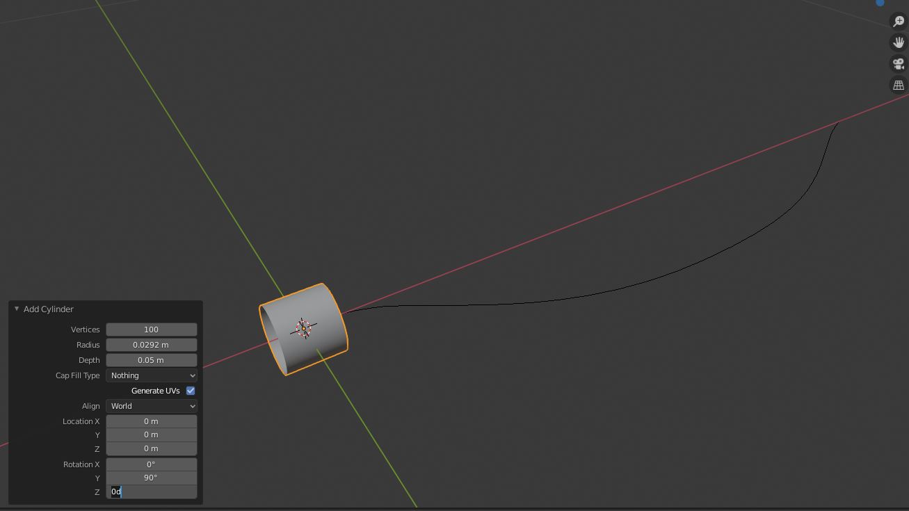
enter image description here

Again, even though the origin is at 0,0,0, the origin is in the middle of the cylinder so you'll need to move the cylinder. Tab into edit mode and move the cylinder by half of the length you used above (make sure you set your transform origin from Normal back to Global). Make sure this is done in edit mode; the origin of the cylinder and the origin of the curve need to be the same for this to work.
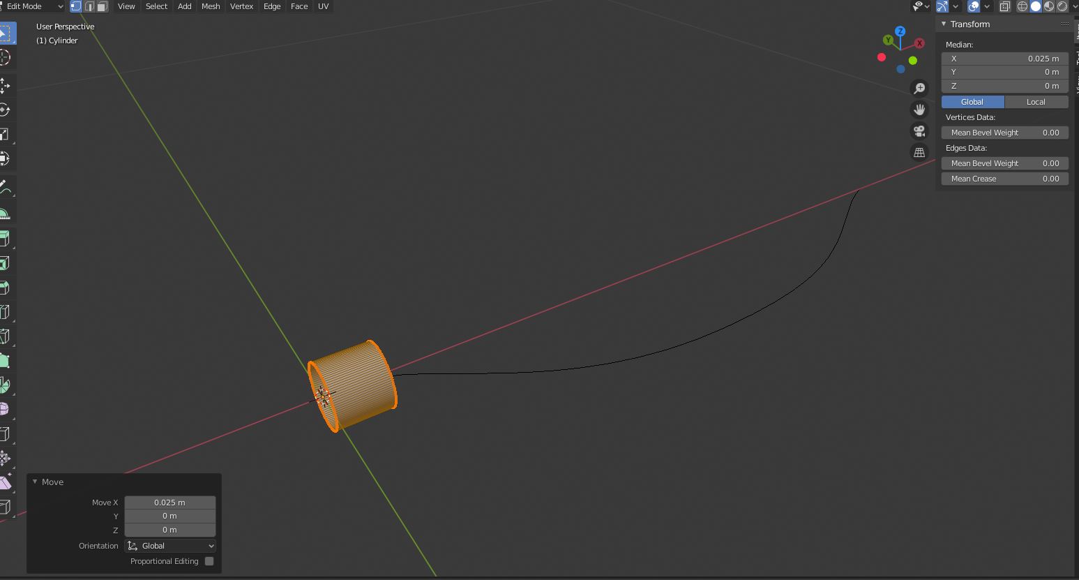
enter image description here

Tab back into Object mode and add an array modifier. It should start with relative offset on the X axis, which is fine. Change the Fit Type to 'Fit Curve' and select the curve. If it looks weird and the array is in the wrong direction, use Ctrl-A and apply the rotation.
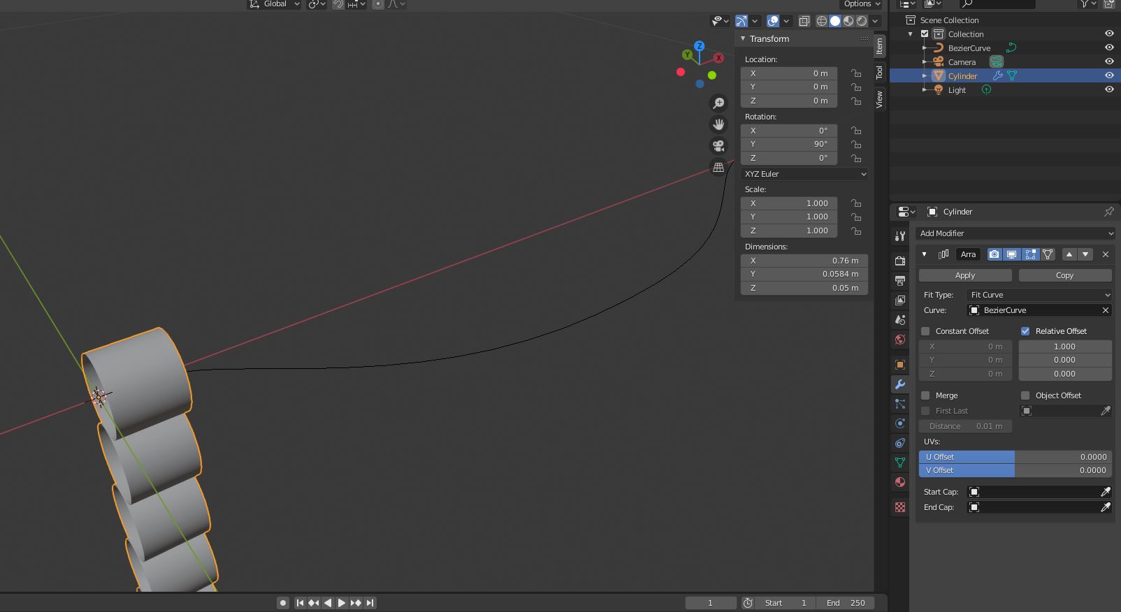
enter image description here

Next, add a curve modifier and select the curve.
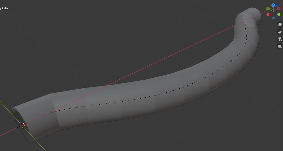
enter image description here

As you can see, it looks a little chunky. Select the cylinder, go into edit mode, and reduce the length of the cylinder along the X axis. You can do this by setting the transform pivot point to the 3D Cursor (assuming it's still at 0,0,0) and using S --> X to scale along the X axis, or use Alt-Z to toggle x-ray mode, select all of the verts at the end of the cylinder (B is box select), and then move them along the X axis back toward the start.
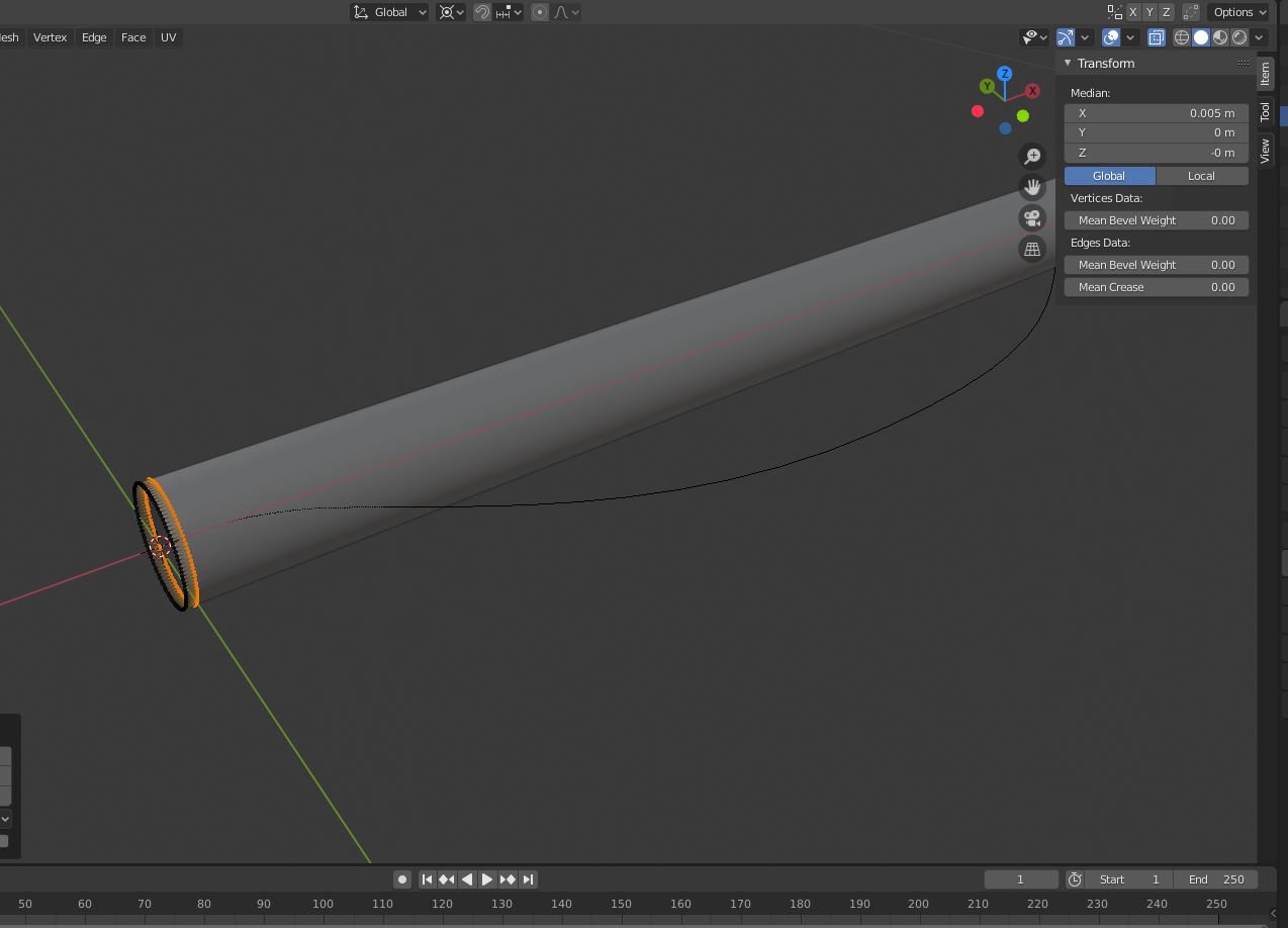
enter image description here

Now, when you go back to Object mode, the cylinder looks a lot smoother.
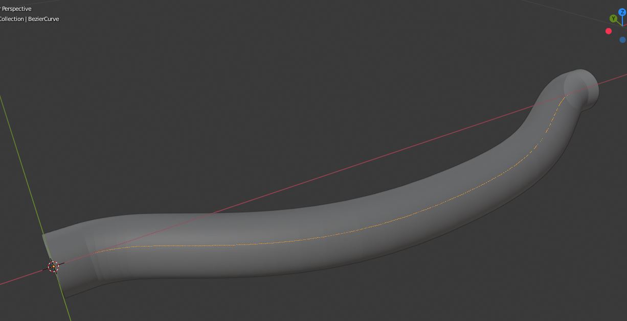
enter image description here

The hose will need to have some thickness so select the cylinder again and add a solidify modifier. An offset of -1 will put the offset on the inside of the cylinder, 1 will put it on the outside. Whether you use the inside or outside will depend on how you measured the radius. Set the thickness to whatever you need it to be, I used 2mm for this example.
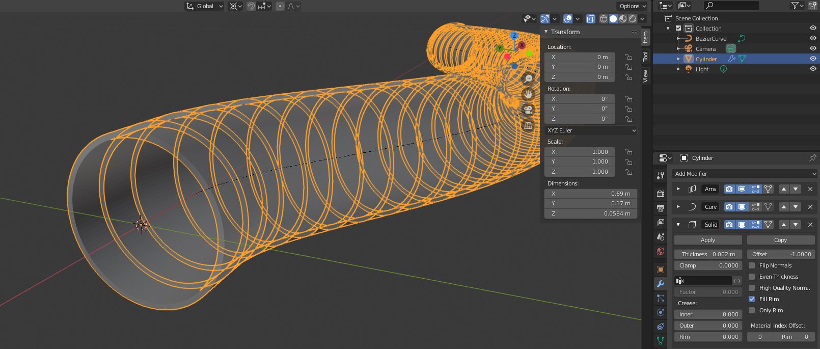
enter image description here

With the cylinder created, now you can select the curve, go into edit mode, and do any tweaking you need to do until it looks right. When you're done, tab back to Object mode, press Alt-Z to leave x-ray mode, and voila! I haven't tried exporting anything to .stl but make sure you check Apply Modifiers when you do.
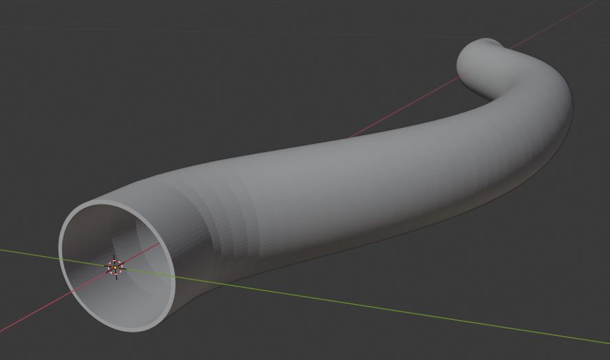
enter image description here

$\endgroup$
1
  • $\begingroup$ Jim thanks for all the work you put into your answer. However, using your method, I was unable to get the precision I need in order to 3D print this part. I have fumbled my way through Blender and come up with a procedure that works which I will outline in another answer to my own question $\endgroup$
    – Claus
    Commented Jun 26, 2020 at 20:11

You must log in to answer this question.

Not the answer you're looking for? Browse other questions tagged .