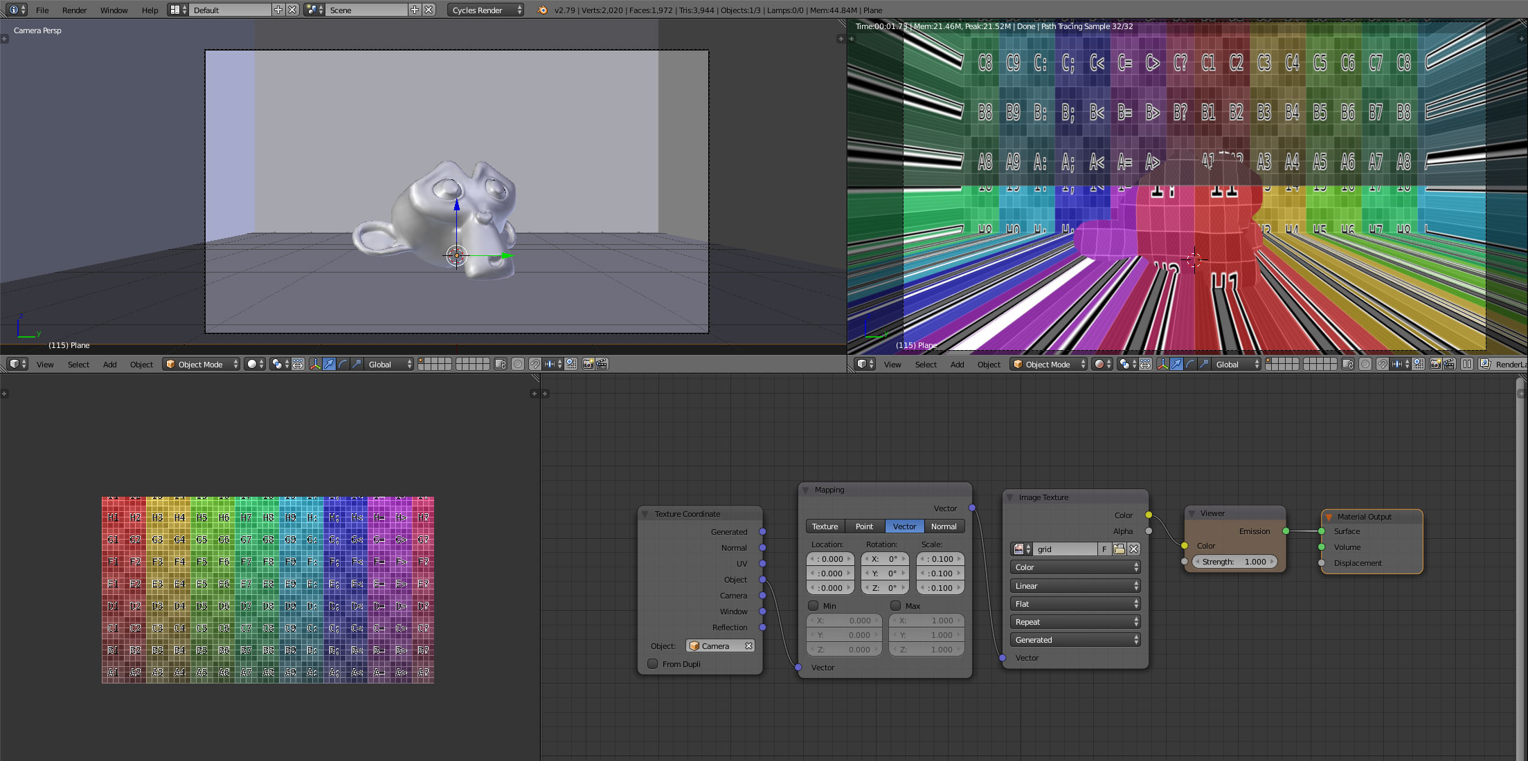
The answer to Projecting Texture onto surface from point produced a material that would project an image from an arbitraty point in the scene through a second point and onto the surface. The same principle can be used to project from the camera by simply constraining the 'origin' point in that example to the location of the camera by way of a Copy Location constraint.
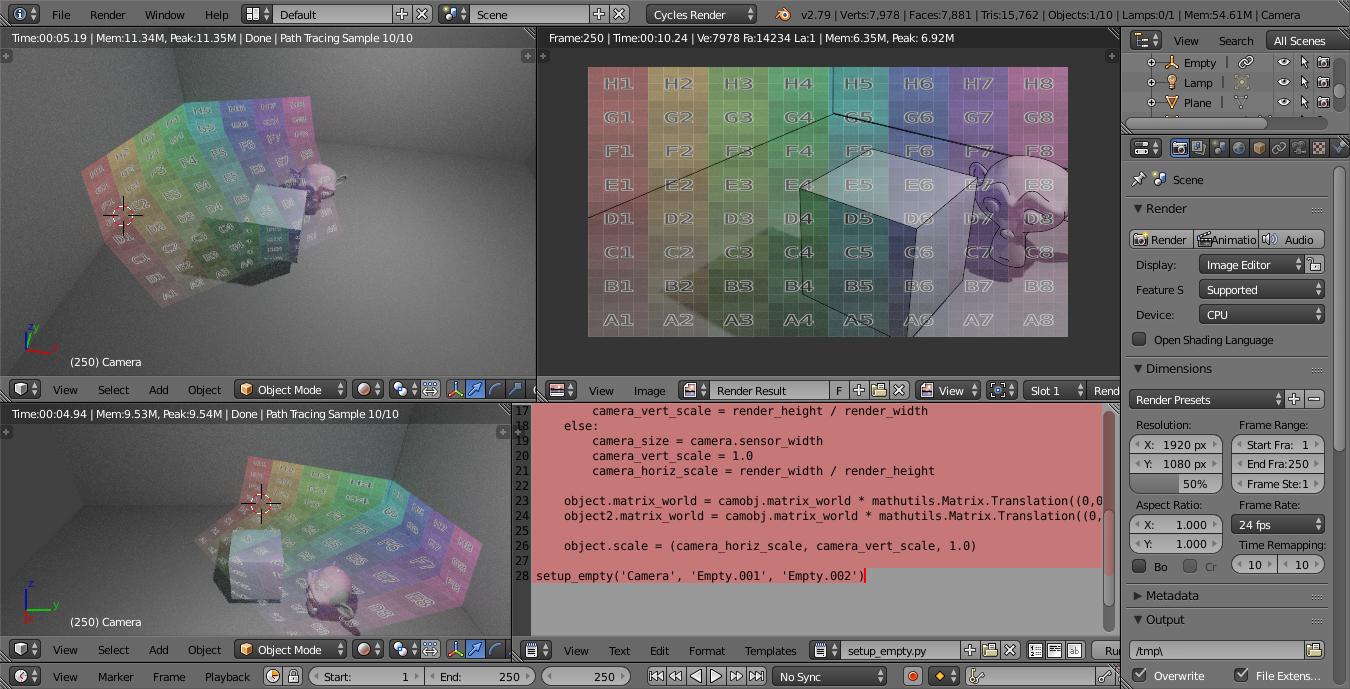
This can produce the following result :
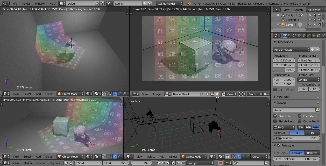
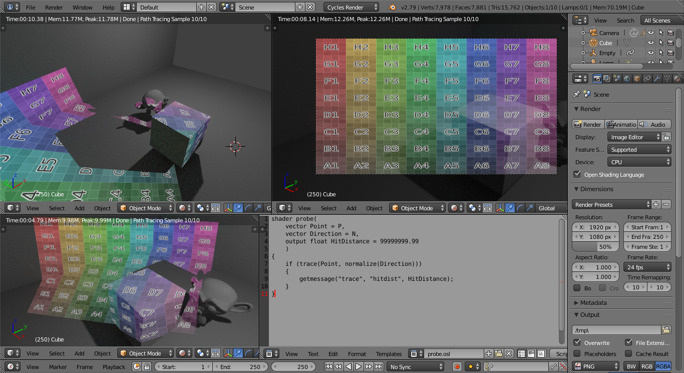
The bottom-right window shows the setup of the scene with Empty representing the 'source' of the projection - constrained to the origin of the camera. Empty.001 is the location of the centre of the 'image plane' to be projected.
The top-right shows the view from the camera - with the projected image showing no distortion (and edges highlighted using Freestyle), while the left-hand windows show the scene from other viewpoints so you can visualise the projection.
Blend file included 
EDIT
You can use the following script to automatically position the empty (Empty.001) used to position the projection image plane centred onto the plane of the camera, taking into account the focal length and sensor size. The empty is also scaled based on the aspect ratio of the render image dimensions.
import bpy
import mathutils

def setup_empty(cam, obj, obj2):

    camobj = bpy.data.objects[cam]
    camera = bpy.data.cameras[cam]
    object = bpy.data.objects[obj]
    object2 = bpy.data.objects[obj2]

    render_width = bpy.context.scene.render.resolution_x
    render_height = bpy.context.scene.render.resolution_y

    if render_width > render_height:
        camera_size = camera.sensor_width
        camera_horiz_scale = 1.0
        camera_vert_scale = render_height / render_width
    else:
        camera_size = camera.sensor_width
        camera_vert_scale = 1.0
        camera_horiz_scale = render_width / render_height

    object.matrix_world = camobj.matrix_world * mathutils.Matrix.Translation((0,0,-camera.lens/camera_size))
    object2.matrix_world = camobj.matrix_world * mathutils.Matrix.Translation((0,1,0))

    object.scale = (camera_horiz_scale, camera_vert_scale, 1.0)

setup_empty('Camera', 'Empty.001', 'Empty.002')
The last line of the script calls the function (setup_empty), passing the names of the Camera, the object to use for the centre of the projection and the object to use to indicate the orientation of the projection. The script will move the two objects into suitable positions around the camera - you can then Parent them to the camera to keep them in place as the camera moves and rotates.
Note that the actual camera dimensions are too complicated to include in the above calculations (I don't know enough about the intricacies of the camera or how to interpret those details in Python) - there are many factors that are included (such as Aspect Ratio, Shift, etc.) - but this script should cope with most 'standard' setups. See also Is there a way to get the dimensions of the camera?
Note also that if you change any significant camera properties (such as Focal Length or Sensor Size) you'll need to re-run the script.
A minor change to the material will allow the scale to affect the image texture by way of two drivers :
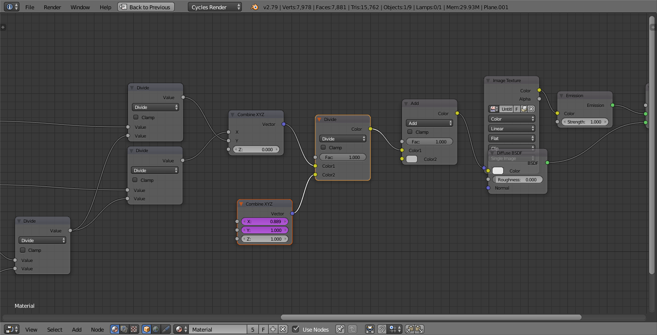
The Combine XYZ node takes the X and Y scale of the empty and scales the vector (via the Divide node) to adjust the aspect ratio of the image to match the camera. The X and Y values are populated via drivers to simply capture the X and Y scale properties of Empty.001.
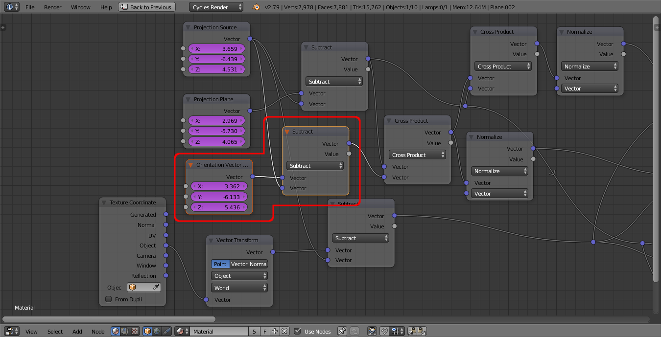
In addition, the other empty (Empty.002) is used to determine the orientation of the camera plane - this is important to correctly orientate the plane of the image so as to align it precisely to the camera. Again, this is fed into the material via a Combine XYZ node and associated drivers for the XYZ coordinates - to calculate the vector from the camera to Empty.002 :
Amended Blend file included 
Assuming you've parented the empty to the camera, moving/rotating the camera should automatically update the projection into the scene.
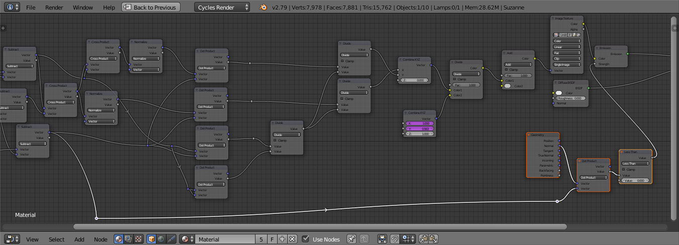
Taking this a little bit further, you can filter out the 'backfacing' faces (those that are facing away from the camera) by combining the vector from the camera to the surface (we already calculate this) with the surface Normal using the Dot Product. The Dot Product will produce a positive output if the two rays are in the same direction and a negative output if the two vectors are in the opposite direction. Adding the following (selected) nodes will therefore mute the emission for those faces that are facing away from the camera :
This produces the following result :
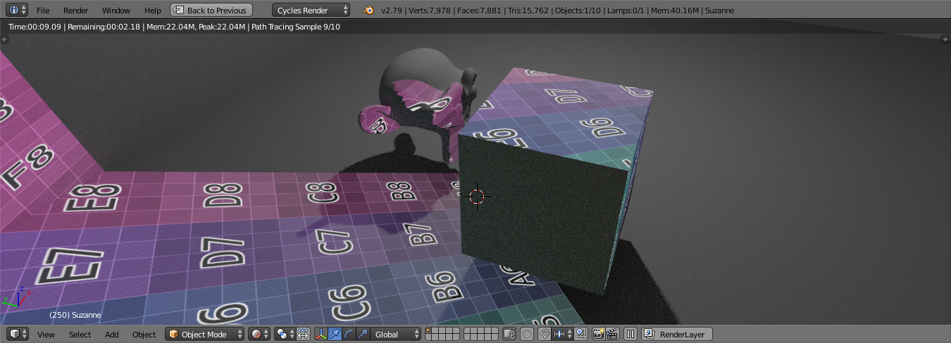
Note : This is not a raytracing solution and therefore objects will not cast 'shadows' in the projection - neither cast onto other meshes or cast onto themselves. Also, meshes must be manifold with correct orientation of surface normals.
In order to obscure the projection we need to be able to trace rays back to the camera from the surface point - just like a shadow ray. Normal nodes are not capable of doing this but OSL can (but using OSL means your shader will be CPU only (no GPU rendering). For this you'll need to enable Open Shader Language in the render settings, then paste the following into a Text Editor block :
shader probe(
    vector Point = P,
    vector Direction = N,
    output float HitDistance = 99999999.99
    )
{
    if (trace(Point, normalize(Direction)))
    {
        getmessage("trace", "hitdist", HitDistance);
    }
}
Name it something like 'probe.osl' and you can now add a Script node to your shader and select your new 'probe.osl' text block. If all goes well, Blender will compile your OSL and give you a new node that can be used to probe out surrounding geometry as follows :
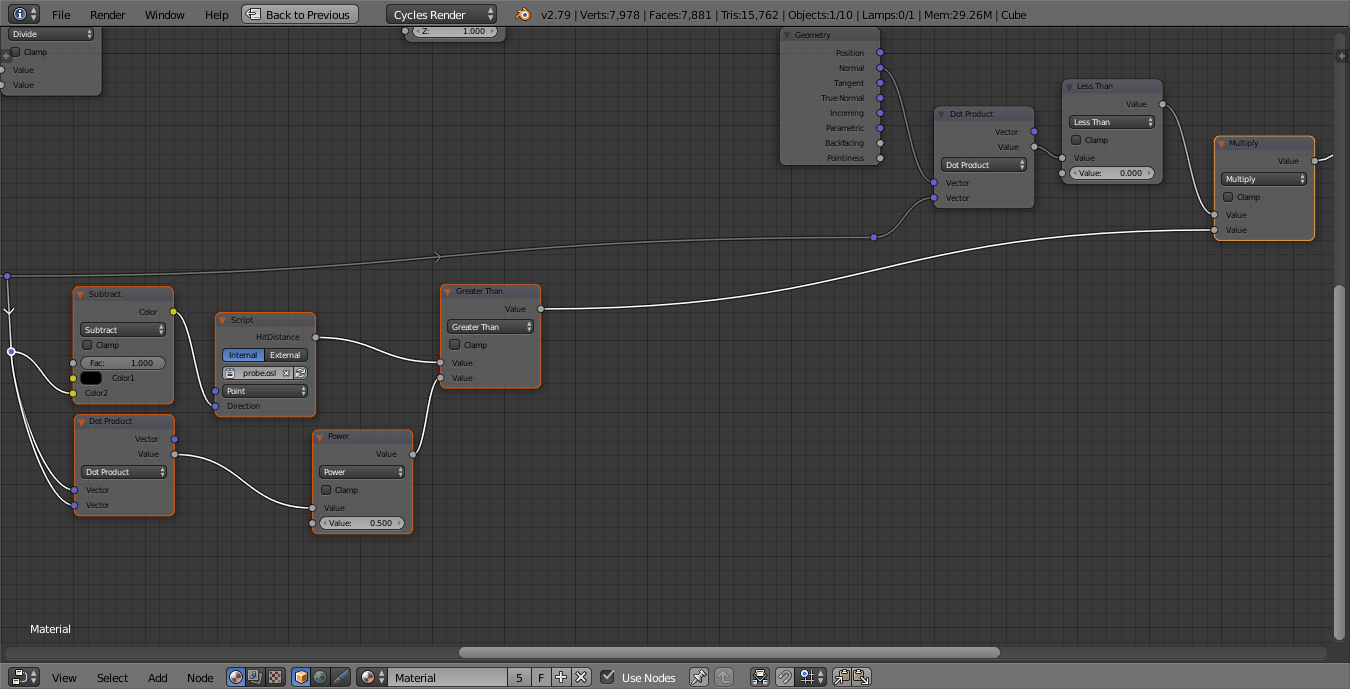
The vector from the camera to the surface point is first negated using the Subtract RGB node (so it points the correct direction) and is also passed into a Dot Product node followed by a Power(0.5) node to determine its length (the distance from the point to the camera). The Script node executes the OSL to trace a ray from the point towards the camera, returning the distance to the nearest surface along that ray. If the 'hit distance' is greater than the distance to the camera then there is nothing obscuring that ray, otherwise it is blocked by intervening geometry - this is used to control the emission of the projected image to create the 'shadow'.
Here's the result - note how the objects now project shadows into the projection :
Blend file included 

