Spline Marching
Theory
Spline marching is a technique in which you move along the spline in discrete steps until you intersect a polygon. One determines—or guesstimate—if one hit a polygon if the distance between the current position and the nearest surface point is less than some small value epsilon. In which case, one can raycast along the tangent at the current spline point or project on the surface of the mesh to get a rather accurate intersection, this argument is supported by the fact that for some small step size, the spline becomes almost linear, that is, straight. However, the final raycast or projection may not be needed as we might see.
Marching using a constant step size is not very efficient, to understand why, consider the situation where the step size is 0.1 unit and the start of the spline is 10 units away from the mesh, then to intersect the mesh, one would need at least 100 steps. A better approach would be to make the step size variable, that is, large in size when you know the mesh is far away and small in size when you know the mesh is near because a large step size near the mesh might pass it without reporting any intersection. So in conclusion, we need the largest step size that is guaranteed not to make the point pass the mesh. The euclidean distance between the current spline point and the nearest surface point is the length of the shortest path, meaning that this distance if used as the step size is guaranteed not to make the point pass the mesh.
Implementation
We construct a loop with an initially zero float input that represents the initial parameter of the spline point, the loop also takes the length of the spline, a BVH tree representing the mesh, the spline itself and a small float input epsilon. In the loop, we evaluate the spline at the parameter and find the distance between the spline point and the nearest surface point on the mesh, this distance is then normalized by divided it by the spline length to remap it to the parameter range [0,1]. The normalized distance is added to the input parameter and the result is assigned to the initial parameter input. What we just did is effectively moving the spline point along the spline based on the distance to the nearest surface point by incrementing its parameter. Finally, we check if the distance is larger than epsilon and break the loop otherwise. The output shall be the input initial parameter which is, when the loop break, the parameter of the spline point whose computed distance is less than epsilon, on other words, the parameter of the point we consider an intersection.
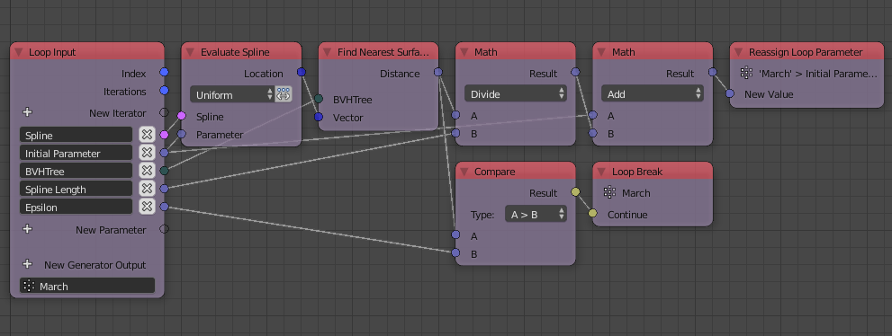
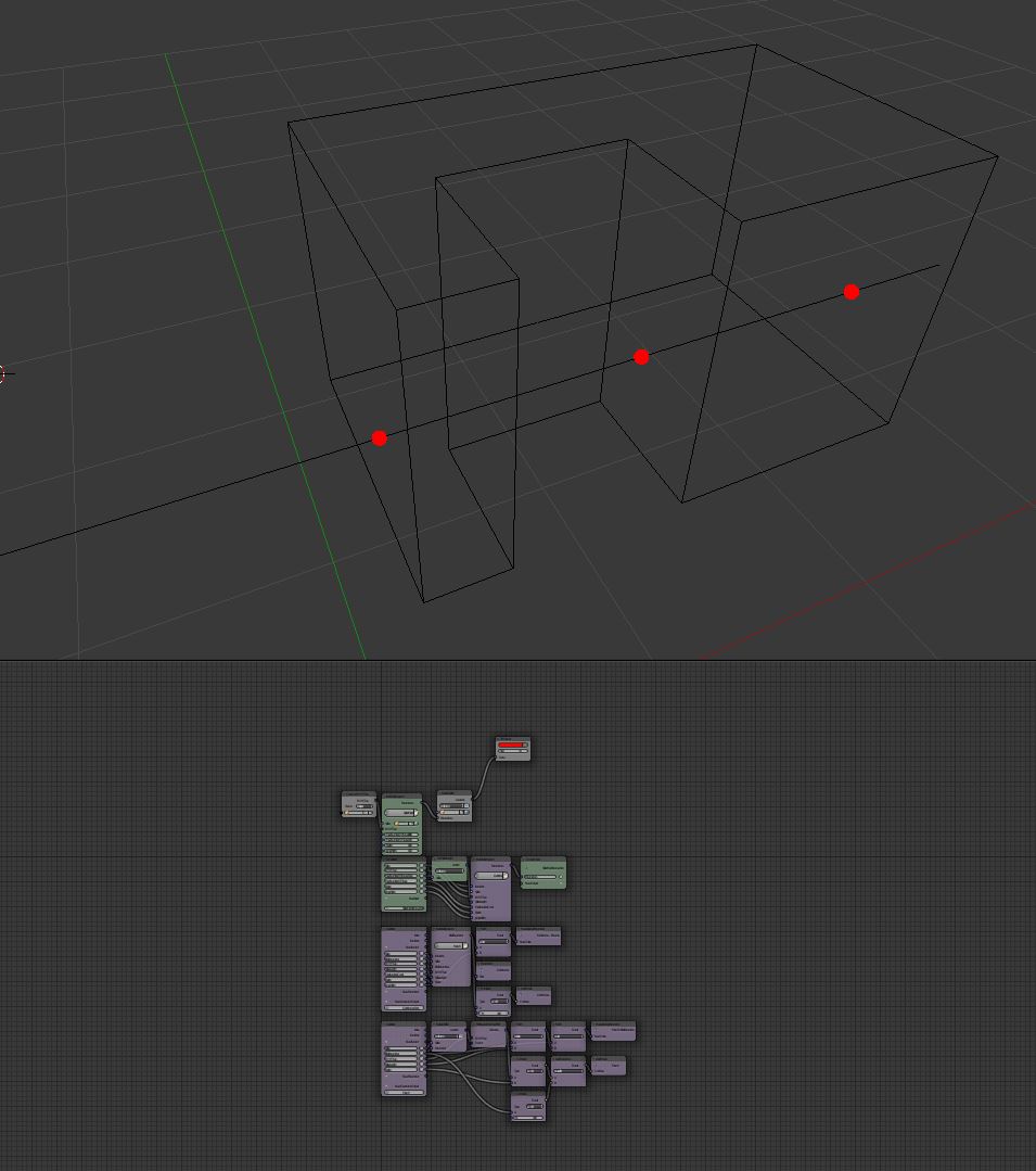
Basically we keep increasing the parameter until we find an intersection. The number of iterations in this case act as the number of steps after which the loops gives up on finding intersections. To try the loop, we set the initial parameter to zero, epsilon to 0.001 and compute the parameter of the intersection, we then evaluate the spline at the computed parameter to get:
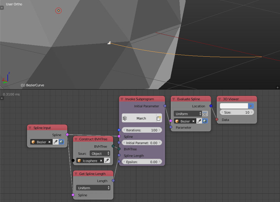
Which is the intersection we expected. If we increased the initial parameter to 0.5, that is, the marching should start from the middle of the spline, we get:
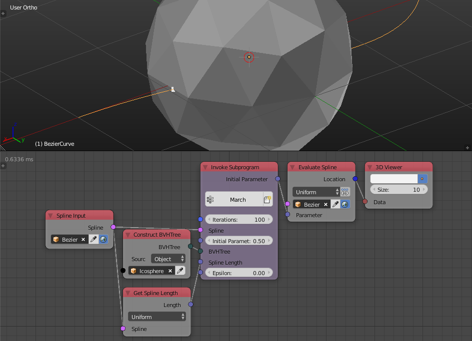
Which is the intersection we expected. If we increase the initial parameter further to 0.75, the loop will execute to the maximum iteration because there are no intersection from this point onward, to avoid this, we are going to implement another condition to check if the end of the spline was reached and break the loop then.
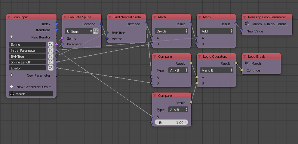
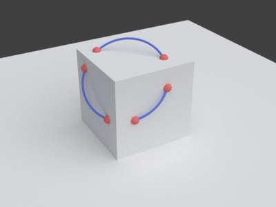
Now the loop is working perfectly. Next step is to implement a loop that generates all intersections automatically. This loop is simple and very similar to the one we create before, we basically find an intersection using the march loop, append it, add a small value jump width to the initial parameter and reassign it. The loop breaks if the parameter became more than 1.
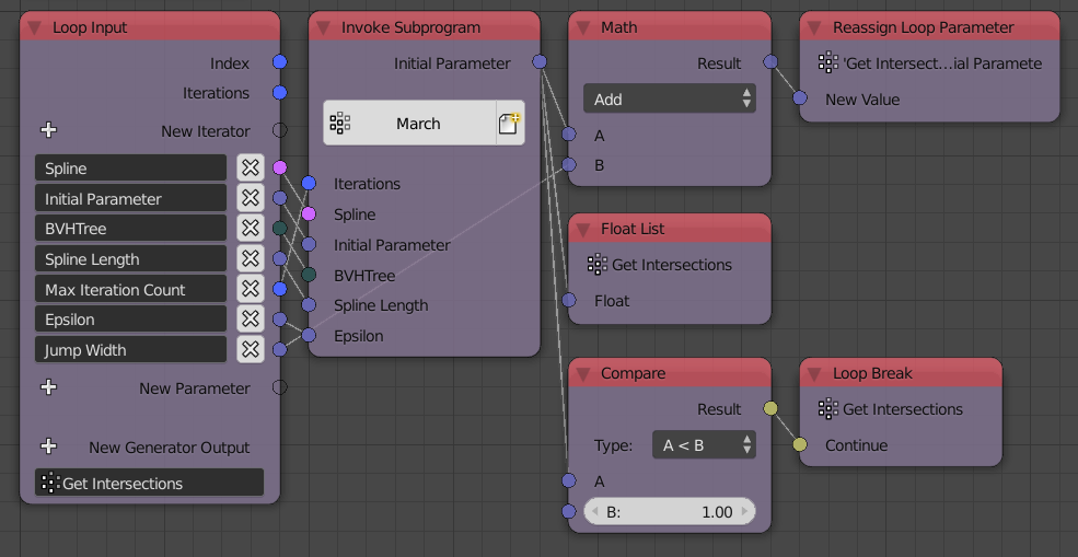
Which gives us exactly what we want.
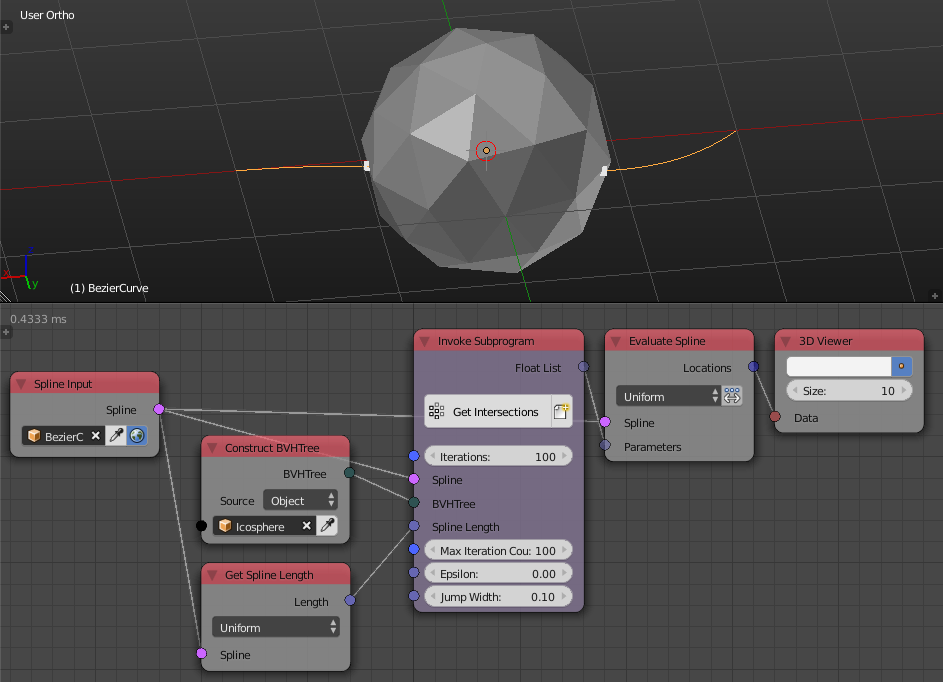
This method is better because it is significantly faster in most cases (the example intersections described above only needed about 4 BVH surface projection), it is consistent so results are exactly as you expect it and it is controllable.
Note:
It is essential that the Evaluate Spline and Get Spline Length nodes to have high resolutions in the Advanced Node Settings this ensures our calculations are accurate as possible.
Blend File:

