0
$\begingroup$

I've run into some problems with my first mesh model, a boat's hull.
I'm unaware of an SE like code review for modelling, so I hope these questions are not frowned upon.

I hereby place it in the Public Domain, except for the image contained from http://www.elb-h-jolle.de/bauvorschrift/bauunterlagen.php (incomplete hull form lines). It's a single mesh with a mirror modifier.

Now to the questions:

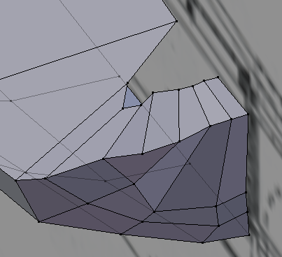
Stern corner mesh joints
I've started with the sides of the hull and added vertices / extruded edges to create faces for the stern and top. Should these be managed as quads or an n-gon?:
Imgur

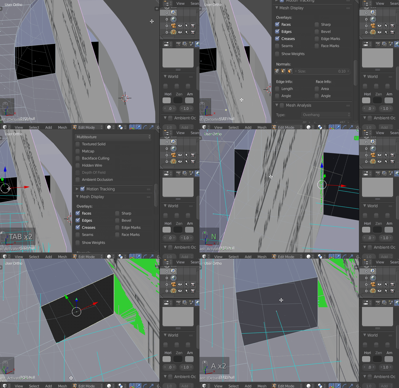
Black hole and unselectable face at bottom of cockpit
I've extruded the front part of the cockpit's bottom (after subdividing two edges to create the corrensponding face), but the resulting vertical face is black (I can select it) - why?
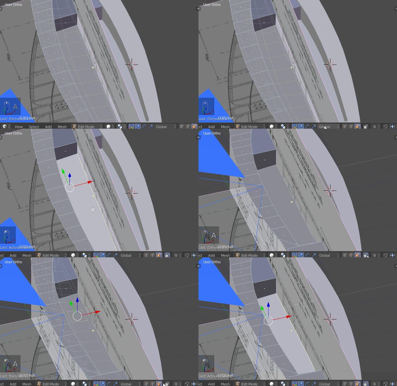
The bottom of the cockpit does not appear to be a face (I can't select it) despite a "Make Edge/Face" operation on the respective Edge loop. Why could this be?
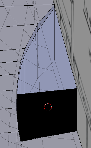
Imgur

Bow
This is missing a curve at the bottom, which is a similar problem the the stern corners. Some of these vertices probably need to be joined?
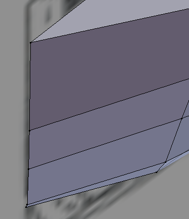
Imgur

Is there a way to align multiple vertices to x=0 at once? If I use the transform (Properties Region) for a selection, this seems to apply to the group, not individually. Alternatively, is it possible to align selected vertices in a plane and move that to the desired location?
Of course the purpose is to align the vertices to close the hull for its mirror modifier.

$\endgroup$
2
  • 1
    $\begingroup$ I am at work so can't check the blend file, but: 1. Quads are always better. Tris and Ngons are 'ok-ish' only for perfectly flat surfaces - where they don't have opportunity to break too much. 2. Colour suggests it might have normal issues, Ctrl+N flips them, it is not a proper help, but might give you some direction to what to look for to fix your problem. 3. Select vertices, press S to scale, press X/Y/Z to choose scaling axis, press 0 to scale by 0. This is old trick that works like everywhere and will flatten positions of all selected verts in relation to selected axis. $\endgroup$ Commented May 14, 2018 at 8:37
  • $\begingroup$ @Mar Thanks! 1) will try to "bend" the mesh so quads are used. 2) normal was flipped indeed, but CTRL+N is assigned to recalculate here, so, Mesh>Normals>Flip Normals (dDisplay via Properties/Mesh Display). 3) Works for me! $\endgroup$
    – handle
    Commented May 14, 2018 at 9:31

1 Answer 1

4
$\begingroup$

Your question is loaded with many questions that appear to be regarding best modeling practices.

Quads vs N-Gons

In general, there are many ways to model something with either quad or n-gons. You have to ask yourself what you would like your end result to be.

  • For example, if you are modeling something that you wish you use a subdivision modifier or use loop cuts, then it is best practice to use quads.
  • If you are modeling a low poly asset that you wish to export to a game engine, then it is also preferable to use quads (that will then get triangulated upon export).
  • If you are modeling something that you wish to render within Blender as is, without the need to subdivide the geometry further, then n-gons are suitable to use as well.

In your case, since the hulls of boats are usually smooth, you may need to add additional loops and/or use subdivision modifier, so it is recommended to use quads.

Normals direction

Your next question is regarding the direction of your normals. If their are pointing inwards, then they appear dark.

  • to enable viewing normals, open up the "N" toolbar by pressing the N key on your keyboard in edit mode, and scroll down to select "view face normals"
  • You can flip the normal of a face by selecting it, and searching for the flip normals command (using the space bar).

enter image description here

Limiting Selection to visible

Based on the file you provided, you cannot select the face at the bottom of the cockpit because you had you have not limited your selection to visible, meaning you can see the bottom faces in solid view.

To enable the option, click the "limit selection to visible" button in the 3d viewport header

Joined vs separate objects

  • Similarly to the consideration required for quads vs n-gons, it's best to think about what is the required end result.
  • If some smootheness (via subdivision modifier or additional edge loops), then it's best to have connected objects. However, they should also be quads.
  • It instead you are modeling disparate elements, then there is no need for the meshes to share vertices.

enter image description here

Best modeling practices

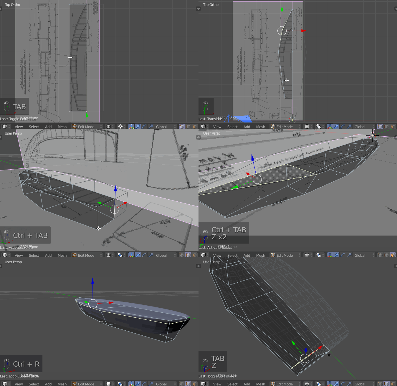
In general with mesh modeling, it is better to start from a single object that you can then subdivide with loop cuts and/or extrusions to get the desired result. I would suggest going through tutorials on youtube.

Below is a quick example of how to model the boat starting from a plane, with a few edge loops, extruding, adding subdivision modifier, and adding additional edge loops to control the softness/hardness of edges.

enter image description here

$\endgroup$
3
  • $\begingroup$ Great response, as for quads vs tris - you could add that you usually try to avoid triangles in parts of geometry that will be deformed during animation. $\endgroup$ Commented May 14, 2018 at 9:49
  • $\begingroup$ Thank you very much! I'll try fixing my mesh as quads first as a learning experience, but if that fails I'll start over and follow your example (I'll have to find a way to "watch" it frame-by-frame). $\endgroup$
    – handle
    Commented May 14, 2018 at 10:09
  • $\begingroup$ Cheers happy to help $\endgroup$
    – dimitarsp
    Commented May 14, 2018 at 11:31

You must log in to answer this question.

Not the answer you're looking for? Browse other questions tagged .