0
$\begingroup$

I created a simple light cone using a mesh which uses a node setup with Subsurf Scattering and Transparent. The mesh is lit by a spotlight lamp. render preview of the light cone setup
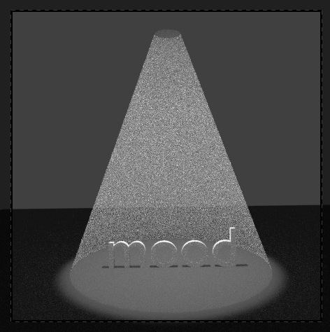
The result is fairly ok for a quick setup (noise is ok as it is just a quick preview :-)), but I would like to add a gradient, so that the very top of the light cone is brighter and near the ground it gets more transparent and you cannot see the lowest edge.

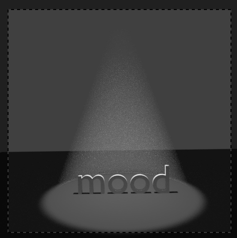
I tried to setup a mix of Texture Coordinate/Mapping/Gradient Texture/ColorRamp and plug it into the Subsurf Scattering node but I did not get the values right. The best I got out of this is:

enter image description here

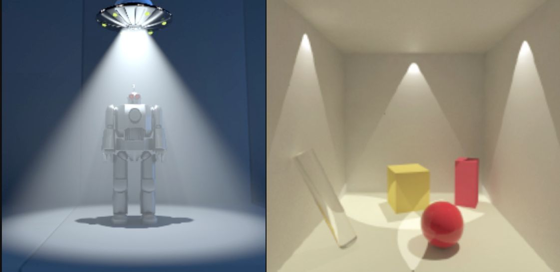
But as you can see the cone is all in all much smoother but I did not achieve the top-down=bright-transparent effect. These are good reference examples as for what I would like to achieve:

light cone references

Any ideas? (Before I tried this setup I also tried to plug the gradient nodes into a Volume Scatter node and this one into the volume of the Output and the Transparent node into the color of the Output: This setup made the desired bright at the top effect but the bottom stayed black/dark and not transparent at all))

$\endgroup$
6
  • 1
    $\begingroup$ I suggest you this simpler approach: blender.stackexchange.com/questions/67309/… $\endgroup$ Commented Dec 16, 2017 at 15:52
  • $\begingroup$ @joshsanfelici thanks for your suggestion. I tried all discussed approaches. If I set up the emission for the cone and plug it into the volume of the Ouput I get a really smooth light cone but have the same problem remaining as before: no gradient: No brighter light at the top. If I go with the volume scatter for the cone mesh and put an emission at the top I get the desired bright light at the top but no matter how strong the emission is there is not enough lighting on the floor at the bottom. $\endgroup$
    – ho.s
    Commented Dec 16, 2017 at 17:03
  • $\begingroup$ In my example there's a gradient texture to control the falloff .... $\endgroup$ Commented Dec 16, 2017 at 17:31
  • $\begingroup$ I set it up just like you (assuming I did no mistake) but I have the same problem as with my example. No matter which mapping values I tweak it just makes no difference - no visible gradient from top to bottom. I updated my file and used your material for the cone in the 2nd (active) layer in the first row. Here is a link to it. $\endgroup$
    – ho.s
    Commented Dec 16, 2017 at 17:56
  • 1
    $\begingroup$ The reason for no gradient is because you need to rotate the texture by 90 on the y axis in the mapping node. Otherwise the gradient is along the x axis and not visible due to the position. You also don't need to change the location at all. $\endgroup$
    – Brenticus
    Commented Dec 16, 2017 at 18:26

1 Answer 1

3
$\begingroup$

As mentioned in the comments under your question, this can be achieved using an emission shader connected to the volume output of a material with a gradient texture controlling the strength.

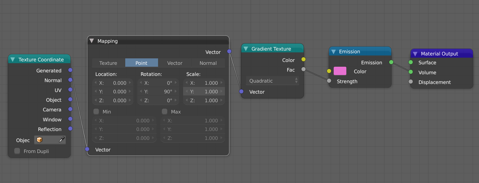
You will need to adjust the coordinates for the gradient texture however, as the default gradient texture has the gradient along the x axis. Using a texture coordinates node with the generated output connected to a mapping node we can position the texture however you like. To get the gradient in the direction you desire you will need to set the Y rotation to 90, which will rotate the gradient texture on the Y axis by 90 degrees, making it look like you want. You can also adjust the length over which the gradient falloff occurs by adjusting the z scale (lower values will stretch the texture more) and the X location (to move it up and down). The reason that you need to use X location instead of Z location is the mapping node applies location, then rotation, then scale, so the 90 degree rotation on the Y axis makes the X location become the Z location.

As josh sanfelici did in his setup, you can add a math node set to multiply (between the gradient texture and the emission shader) to control the strength, however in many cases you can get away with only positioning and scaling the texture to suit your needs.

Here is a node setup that will do what you want: enter image description here

$\endgroup$
1
  • $\begingroup$ thanks again for your detailed answer.. helped a lot understanding what each node does $\endgroup$
    – ho.s
    Commented Dec 16, 2017 at 21:52

You must log in to answer this question.

Not the answer you're looking for? Browse other questions tagged .