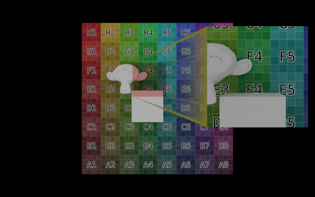
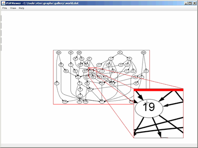
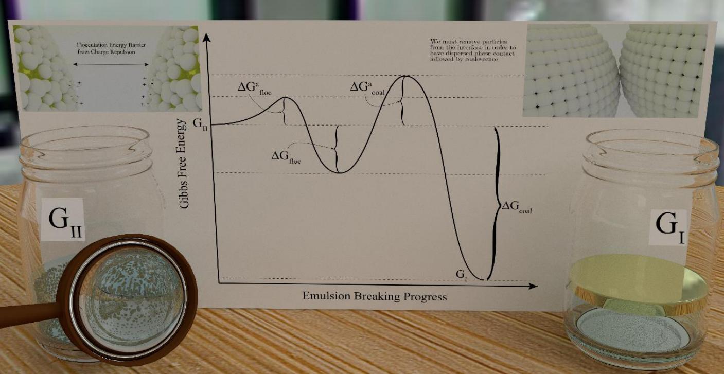
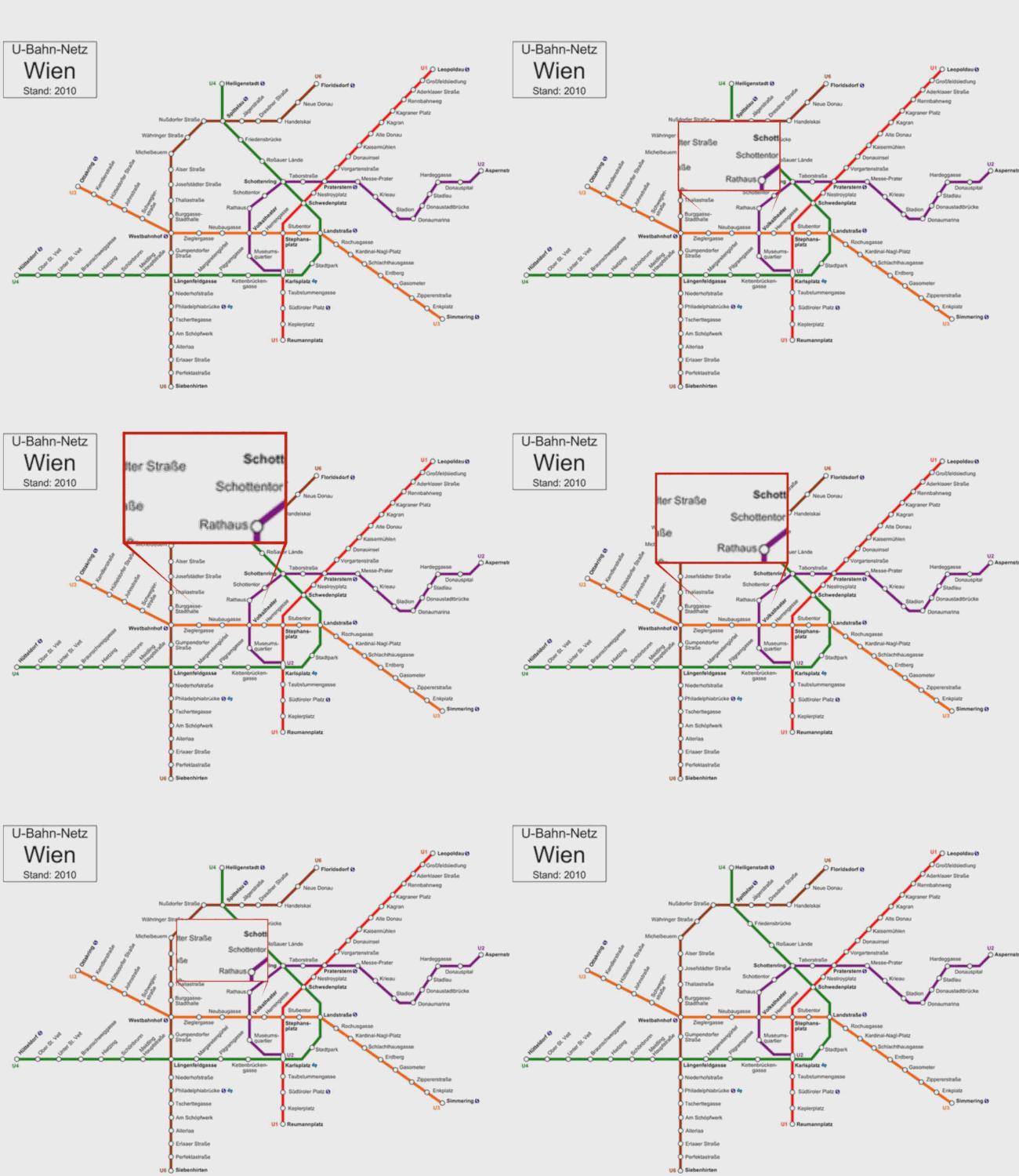
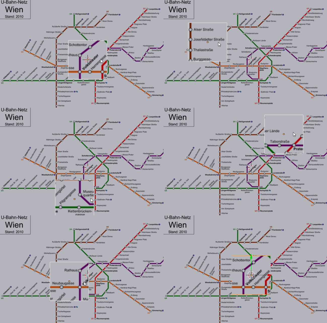
An alternative solution is to use a Refraction shader. Since this does not require changes to the geometry of the original "image" it can be very easily animated.
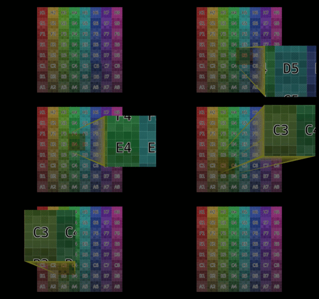
The key is to be able to control the bending of each ray hitting a surface (the zoom window) into a particular direction, irrespective of the incoming angle of the ray. This allows the camera rays to be directed towards a specific area of the distant image to visually 'lift' a section of the image closer to the camera (similar to Paul Gonet's excellent answer but without actually changing the geometry).
Normally the Refraction shader will bend the incoming ray based on the refractive index and the incoming light ray path. For rays 'entering' a denser material, the rays will typically bend towards the surface normal. For rays 'leaving' a denser material the rays will bend away from the surface normal - with the amount of bending based on the angle of the incoming ray (so rays along the Normal will not be bent but those at steeper angles will be progressively more bent).
A surface with an infinite refractive index would bend all incoming rays so that they exit along the surface normal. Similarly, a surface with a refractive index of zero will bend all 'outgoing' rays along the surface normal. Since we can control the direction of the surface normal we can use this to control the precise direction of any rays passing through the surface. Note that we can't actually enter a refractive index of infinity (the node doesn't allow it), but the same effect is achieved by flipping the normal (so rays hit the surface from the "back" and use an IOR of zero.
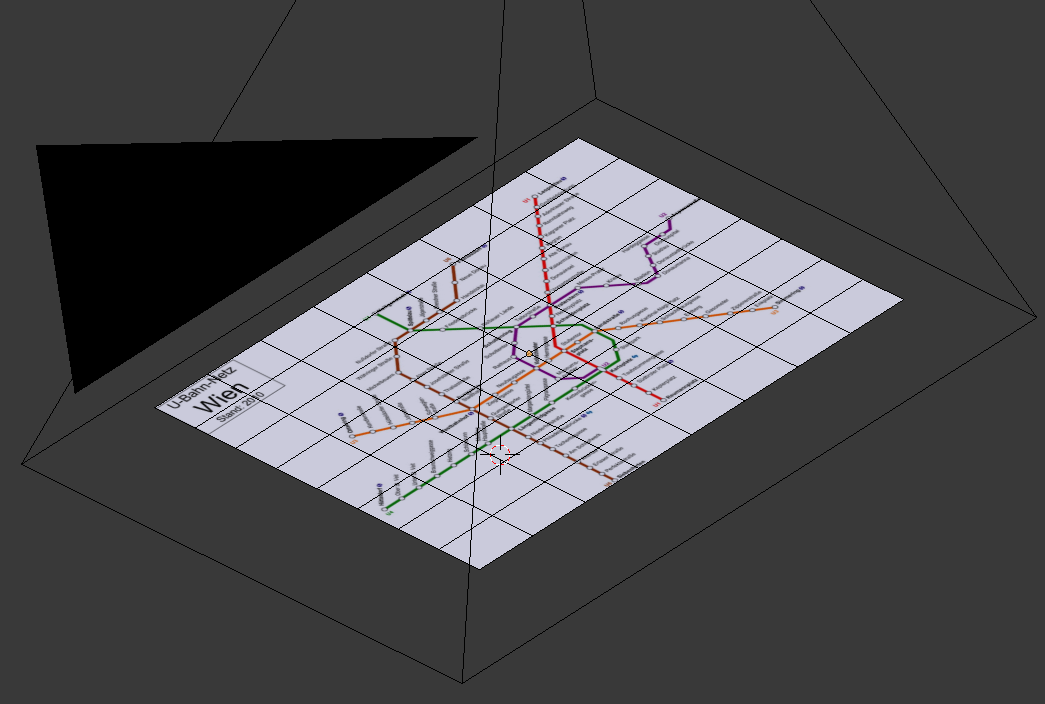
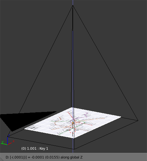
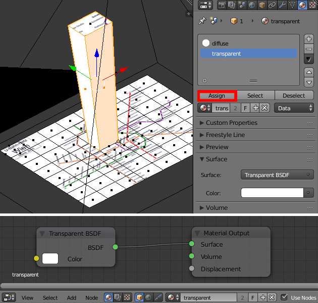
To start with, create a plane to act as the 'start' of the pipe (the 'zoom window'). Set its dimensions as desired and duplicate it (Shift-D) to create an exact copy to be the 'end'. Create the following material and assign it to the 'end' plane - this will be used to highlight the area of the image that is currently being zoomed :
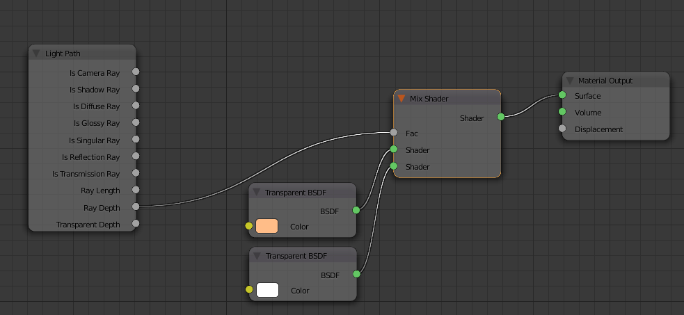
Note that the material mixes between a pair of transparent shaders based on the Ray Depth, each with different colours. The plain white transparency is to ensure the material is invisible when viewed through the zoom window (we don't want that tinted), whereas the coloured transparency highlights the section of the original image being shown in the zoom window.
Create the following material and assign it to the 'start' plane :
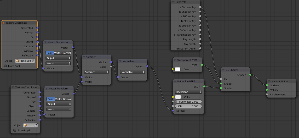
Note the Refraction shader with IOR set to 0.000. Flip the normal of the plane (or rotate it around the X or Y axis by 180 degrees) so that the camera sees the back face of the plane. To direct the rays in a particular direction we now only need to feed the desired direction vector into the Normal of the Refraction shader. The nodes on the left-hand side of the material achieve this by calculating the difference in location (in world space) between the 'start' plane (the lower Texture Coordinate node) and the 'end' plane (the upper Texture Coordinate node - note the use of the Object field to indicate that the coordinate should be in relation to the 'end' plane).
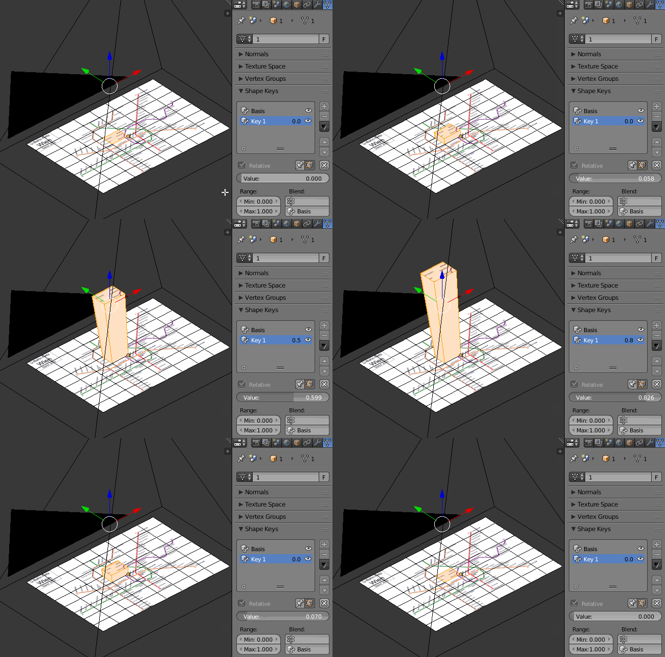
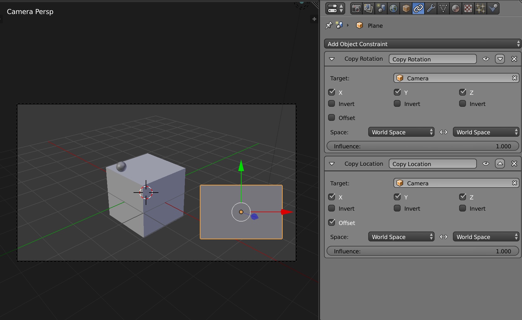
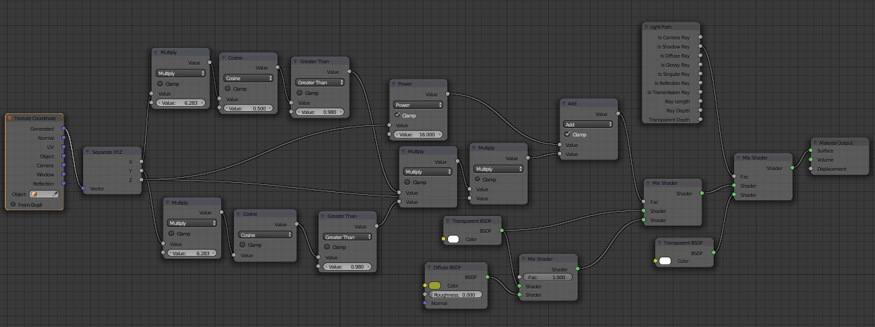
The 'zoom lines' are added by way of a Cube that is 'hooked' at one end to the 'start' plane and the other end to the 'end' plane - so that it stretches between the two. I removed the top and bottom faces to avoid z-fighting with the start and end of the "light pipe", then selected each set of vertices in Edit mode and selected 'Hook to new object' - this creates a new empty that can be tied to each of the 'start' and 'end' planes using parenting or a Copy Location constraint. The cube is shaded with a material to hightlight the edges and fade out towards the 'end' :
Final result :
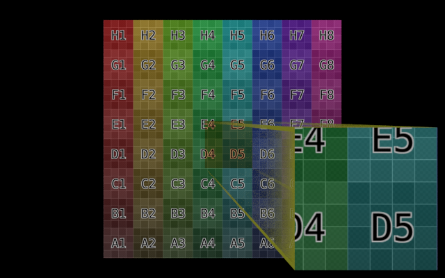
From here it's fairly simple to add decoration around the zoom window and/or change the appearance of the 'zoom lines' cube for the desired effect.
Blend file attached 
One drawback of this is that the 'target' area (the shaded part of the target image) must be close to the surface of the flat image - otherwise the direction of the light path can affect the area visible in the zoom window. This can be be best illustrated with a diagram :
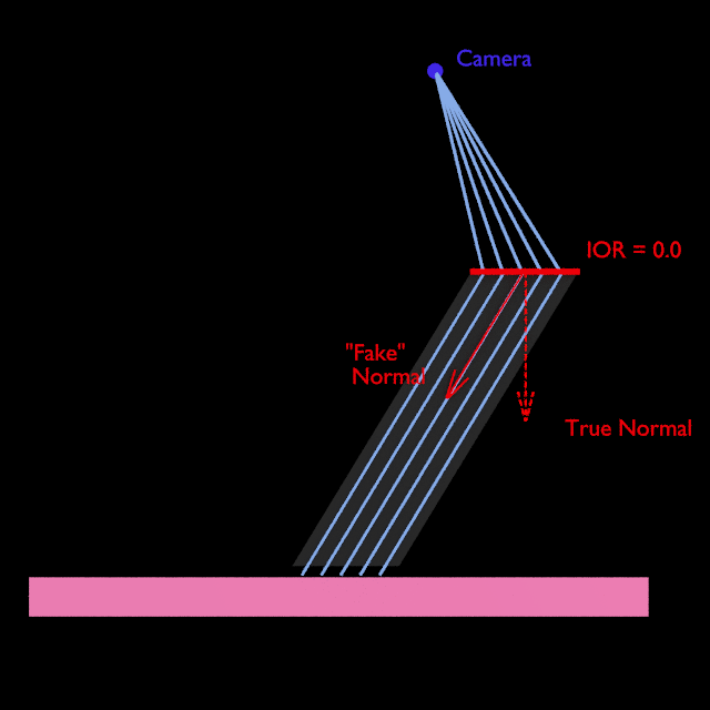
If the "light pipe" does not end close to the surface then the rays will hit a region to the side of the target - a second refraction surface can be used to 'correct' the path of the rays so that they are directed towards the surface.
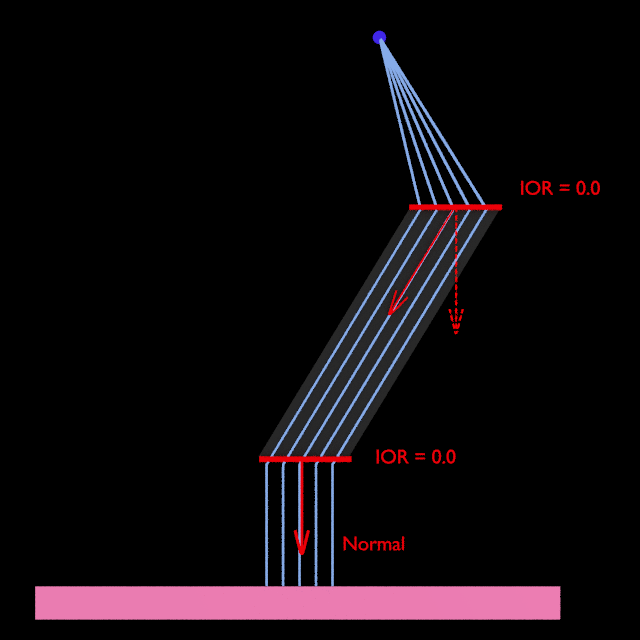
The only issue remaining is that the rays emanating from the end of the 'pipe' are parallel. This works fine where the target is a simple plane but will lose any sense of perspective if the target is a more complicated scene. To fix this we can adjust the refraction plane used for the 'end' of the pipe to act like a lens. Adjusting the focal length of the 'lens' will affect the depth of the perspective.
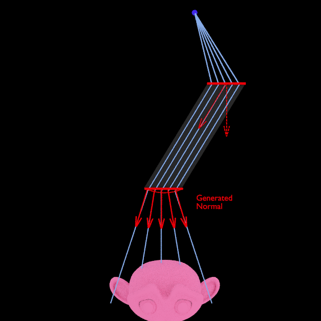
The material for this is as follows :
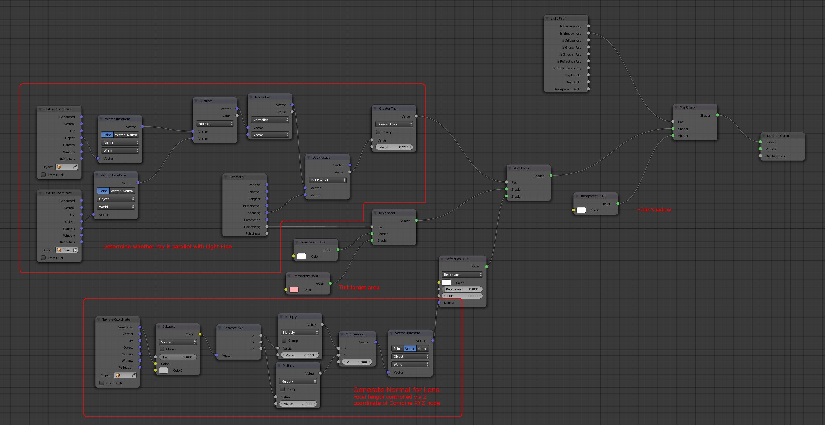
(Edit : strictly speaking the Vector Transform at the bottom centre of the above image should be set to Normal mode so as to produce a correct Normal!)
Note that the 'lens' is an approximation since it is a plane rather than an actual curved surface (and the calculation is greatly simplified) - objects close to the lens can become distorted. Adjusting the 'Z' coordinate of the Combine XYZ node will adjust the focal length.
