Quick Method
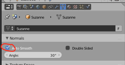
Basically, what we want to do is find the Dot Product between the normals of a bounding ellipsoid projected on to the mesh, and the normals of the mesh. First, enable Auto Smooth normals.
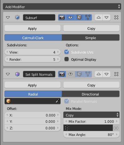
Next, add a Normal Edit modifier after a Subsurf Modifier (4 to 5 subdivisions) and set the Angle on the Normal Edit modifier to about 80 degrees. This will give us the approximate projected normals of the bounding ellipsoid.
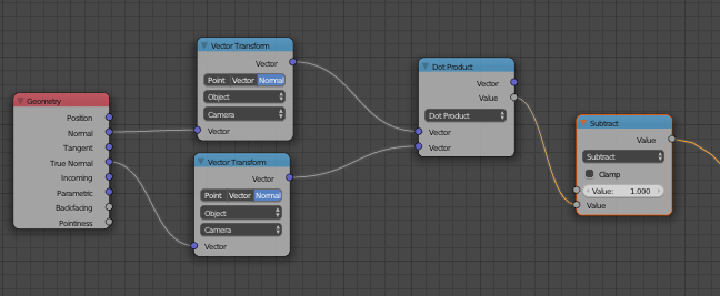
Finally, add a Geometry Node and take the Dot Product of the (modified) Normal and (original) True Normal inputs (with vector transform) (it doesn't matter).
Result:
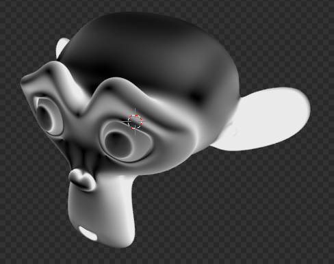
To increase the contrast, you can square the output with a Math node.
More Mathematically Accurate, Plus it Doesn't Mess Up Your Normals
The method above finds the projected normals of the bounding ellipsoid using Auto Smooth in combination with a Normal Edit modifier. This has some limitations: 1) the resolution of your map is tied to the number of faces you have, slowing down rendertimes, 2) the Normal texture coordinates are messed up, so to have "normal"-looking normals, you have to use True Normal, which is again tied to the face count, and 3) the map just isn't as detailed as it could be, due to limitations of the Normal Edit modifier.
If you are willing to work with OSL (Open Shading Language), you can avoid all this with some code.
First, we need to figure out a way to project the normals of the bounding ellipsoid on to the mesh (in this case, Suzanne). I found this helpful, if dense, article here. The important part we need to pull out of this are these equations:
$$y_0=x_0\left(1+\frac{t}{e_0^2}\right),y_1=x_1\left(1+\frac{t}{e_1^2}\right),y_2=x_2\left(1+\frac{t}{e_2^2}\right)$$
where the x's are the coordinates of a point on the mesh, the y's are the coordinates of a point on the ellipsoid, the e's are the axis-aligned radii of the ellipsoid, and t is a certain value that makes everything right (more on that later).
Let's see if this method even works. I drew up a proof of concept in Desmos. You can look at it here. By moving the red dot labeled "Point on Mesh", we can see the algorithm finding the closest point on the ellipse, we just have to manually adjust the t value.
While having to manually find the t value isn't ideal, it is only one variable. We can use a for loop to iterate through a bunch of values and figure out which value best gives a point that solves the equation for an ellipsoid:
$$\left(\frac{x_0}{e_0}\right)^2+\left(\frac{x_1}{e_1}\right)^2+\left(\frac{x_2}{e_2}\right)^2=1$$
(naming conventions the same as above)
So, what should our inputs and outputs be? We need the Object coordinates as an input to give us the coordinates of our mesh point, and the Dimensions of our object (X, Y, and Z), both vectors. Since we are calculating t with a for loop, we'll need an iterations count, and a step value to set the detail. As far as outputs go, we need a map of the stretch (dot product), and, just for fun, the ellipsoidal normals.
Let's start coding! Create a new text file in the Text Editor (or something else) and name it stretch.osl. Set inputs and outputs, and declare our variables:
#include "stdosl.h"

shader stretch(
    /*Set Inputs*/
    vector Object = P,
    vector Dimensions = vector(1),
    int iterations = 200,
    float step = 0.05,
    /*Set Outputs*/
    output float Fac = 0,
    output normal Ellip = 0
)
{
    /*Point on Mesh*/
    float X0 = Object[0];
    float X1 = Object[1];
    float X2 = Object[2];
    /*Radii of Ellipsoid*/
    float E0 = Dimensions[0];
    float E1 = Dimensions[1];
    float E2 = Dimensions[2];
    /*Point on Ellipsoid*/
    float Y0 = X0;
    float Y1 = X1;
    float Y2 = X2;
    /*t value*/
    float t = 0;
}
Next, we need to figure out how accurate we want to be. Since we don't want our algorithm to take ridiculously long (or fall prey to floating point errors), we need to figure out how many significant figures is reasonable. I chose 3. Unfortunately, OSL doesn't round to a certain number of significant figures, only to whole integers, so we have to write our own significant figures rounding function. Place it at the beginning of the code, below #include "stdosl.h":
#include "stdosl.h"

float sfround(float num, int d){
    num = num * pow(10, d - 1);
    num = round(num);
    num = num / pow(10, d - 1);
    return num;
}
For the next part of our algorithm, we need a way to figure out how close we are to having an accurate t value. As we saw in the Desmos test, when the t value is correct, plugging numbers back in will yield 1. Let's write a small function to calculate this for us. Place it after the variable declarations:
    float onEllipsoid(){
        return sfround(pow(Y0, 2) / pow(E0, 2) + pow(Y1, 2) / pow(E1, 2) + pow(Y2, 2) / pow(E2, 2), 3);
    }
Now we can write our for loop! Place it below the onEllipsoid() function. I've commented in what everything means.
    for(int i = 0; i < iterations; i++){
        if(onEllipsoid() < 1.0){ /*Point inside ellipsoid*/
            t = t + step;
        }else if(onEllipsoid() > 1.0){ /*Point outside ellipsoid*/
            t = t - step;
        }else{ /*Point on ellipsoid*/
            break;
        }
        /*Refine point estimate*/
        Y0 = X0 * (1 + t / pow(E0, 2));
        Y1 = X1 * (1 + t / pow(E1, 2));
        Y2 = X2 * (1 + t / pow(E2, 2));
    }
To finish it off, we need to turn the point we got into a normal. We can use this answer off of Math SE to accomplish this.
normal elliptic = normalize(2 * vector(Y0 / pow(E0, 2), Y1 / pow(E1, 2), Y2 / pow(E2, 2)));
Now, all that is left to do is to write our answer to the outputs:
    Ellip = elliptic;
    Fac = dot(elliptic, N);
TL;DR - Just Give Me the Code
#include "stdosl.h"

float sfround(float num, int d){
    num = num * pow(10, d - 1);
    num = round(num);
    num = num / pow(10, d - 1);
    return num;
}

shader stretch(
    /*Set Inputs*/
    vector Object = P,
    vector Dimensions = vector(1),
    int iterations = 200,
    float step = 0.05,
    /*Set Outputs*/
    output float Fac = 0,
    output normal Ellip = 0
)
{
    /*Point on Mesh*/
    float X0 = Object[0];
    float X1 = Object[1];
    float X2 = Object[2];
    /*Radii of Ellipsoid*/
    float E0 = Dimensions[0];
    float E1 = Dimensions[1];
    float E2 = Dimensions[2];
    /*Point on Ellipsoid*/
    float Y0 = X0;
    float Y1 = X1;
    float Y2 = X2;
    /*t value*/
    float t = 0;

    float onEllipsoid(){
        return sfround(pow(Y0, 2) / pow(E0, 2) + pow(Y1, 2) / pow(E1, 2) + pow(Y2, 2) / pow(E2, 2), 3);
    }
    for(int i = 0; i < iterations; i++){
        if(onEllipsoid() < 1.0){ /*Point inside ellipsoid*/
            t = t + step;
        }else if(onEllipsoid() > 1.0){ /*Point outside ellipsoid*/
            t = t - step;
        }else{ /*Point on ellipsoid*/
            break;
        }
        /*Refine point estimate*/
        Y0 = X0 * (1 + t / pow(E0, 2));
        Y1 = X1 * (1 + t / pow(E1, 2));
        Y2 = X2 * (1 + t / pow(E2, 2));
    }
    normal elliptic = normalize(2 * vector(Y0 / pow(E0, 2), Y1 / pow(E1, 2), Y2 / pow(E2, 2)));

    Ellip = elliptic;
    Fac = dot(elliptic, N);
}
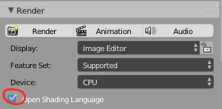
Well, now that we have the code, how do we use it? First, we need to enable OSL under the render settings.
Next, add a Script node with Shift + A > Script > Script and select the stretch.osl file, or whatever you named it. We need to give it the Object coordinates, and the dimensions of your object. Since my Suzanne object doesn't rotate, deform, or scale, I just copy-pasted the information out of the 3D Viewport (below the transforms in the N panel). If this doesn't work for your situation, it wouldn't be hard to implement drivers. Anyway, just copy the X, Y, and Z values into a Combine XYZ (Shift + A > Converter > Combine XYZ ) node and plug it in.
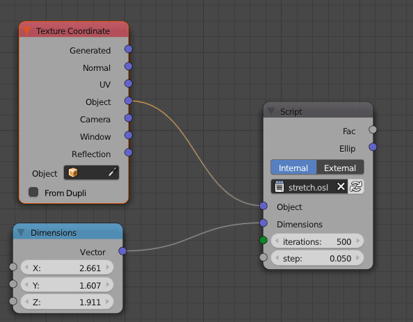
As far as the iterations and step values go, the default step should be fine; adjust the iterations until there isn't a visible change in the Fac output (it happens really slowly (depending on your step value), so use increments of at least 25 at first).
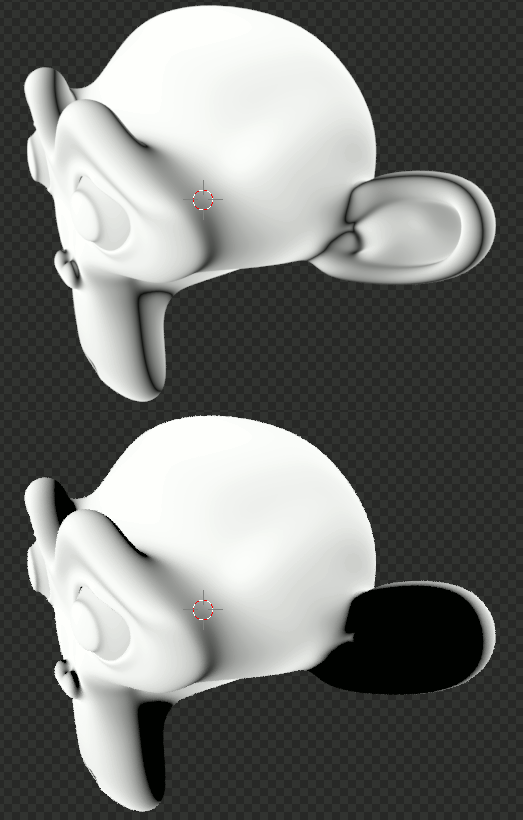
Now, a word on the Fac output. Black is more distorted, not white, and subtracting the output from 1 doesn't work to make it that way. Here's why: using Suzanne as our example, there are some areas like the ears or the back of the chin where the closest point is facing into the mesh. In the Fac output, this will look like a big black patch. In reality, it is just a negative value, showing a different kind of distortion. If we plug the Fac value into a Math node (Shift + A > Converter > Math ) set to Absolute, we can see that they are just negative values. Here is a GIF switching back and forth:
Anyway, hope this helps. It was fun to work on ;-). Congrats for reading this far!


