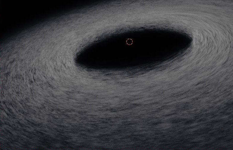
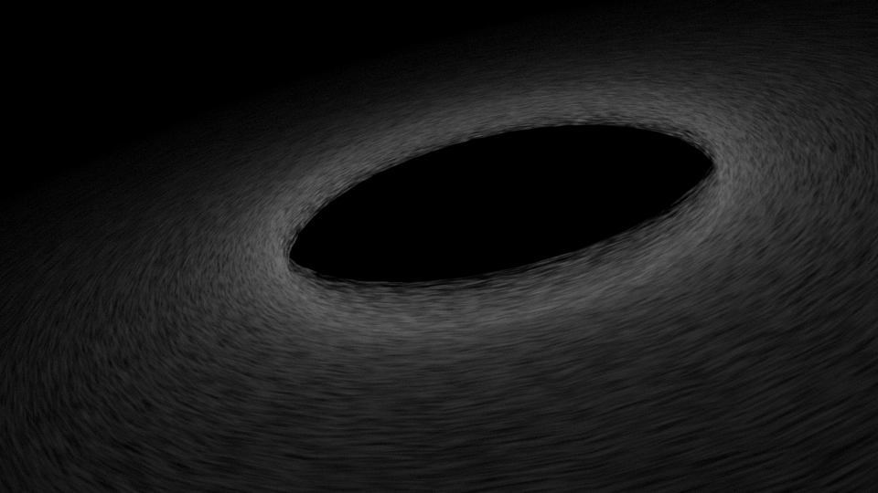
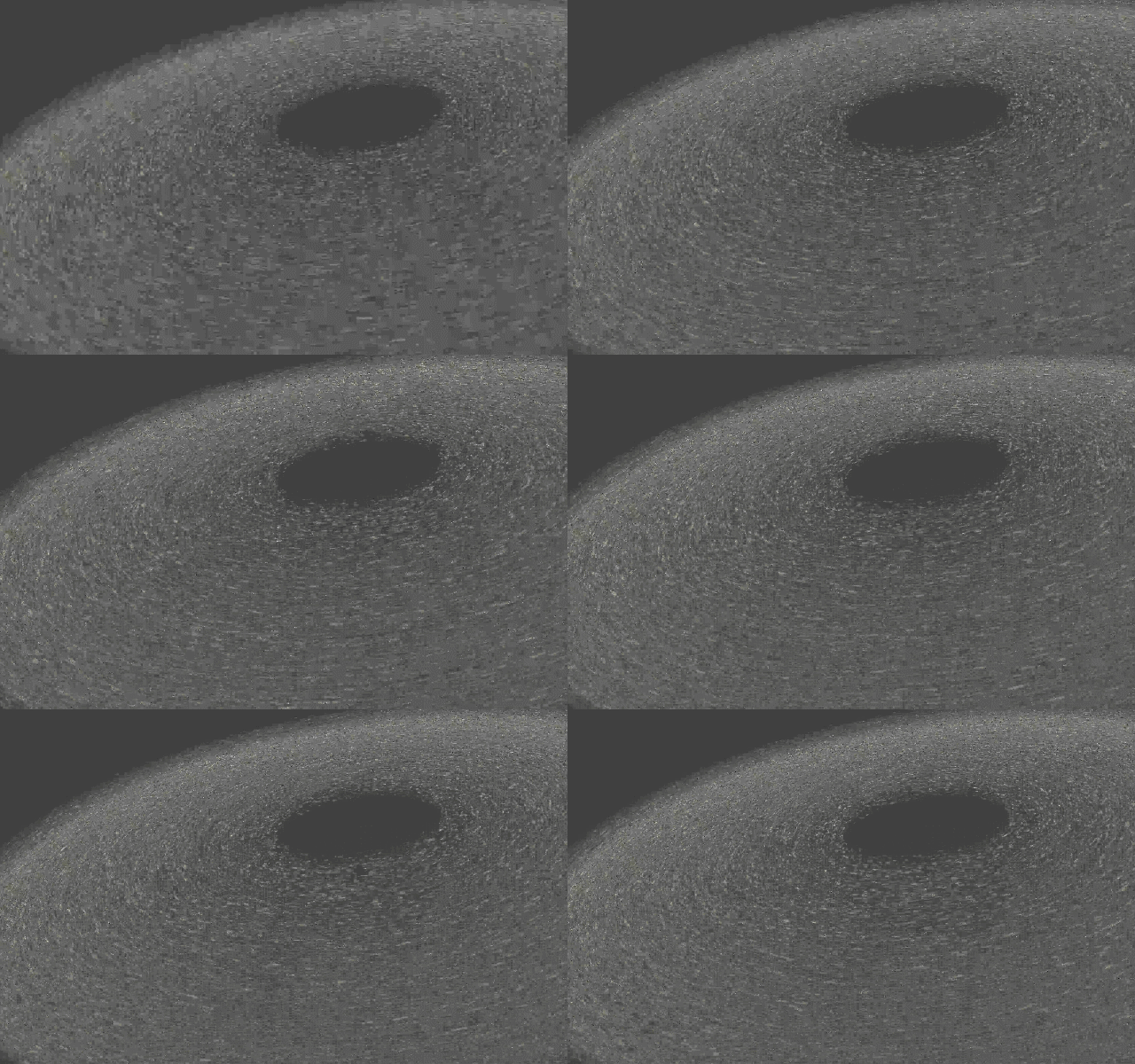
How do I swirl a procedural texture to get a result similar to this?
-
3$\begingroup$ What render engine are you using? $\endgroup$– 10 RepliesCommented Dec 9, 2016 at 13:01
-
$\begingroup$ If you see an answer that solved your problem, please accept it. Thanks! :) $\endgroup$– Reinis MazeiksCommented Feb 6, 2018 at 17:37
2 Answers
The Hacky Way
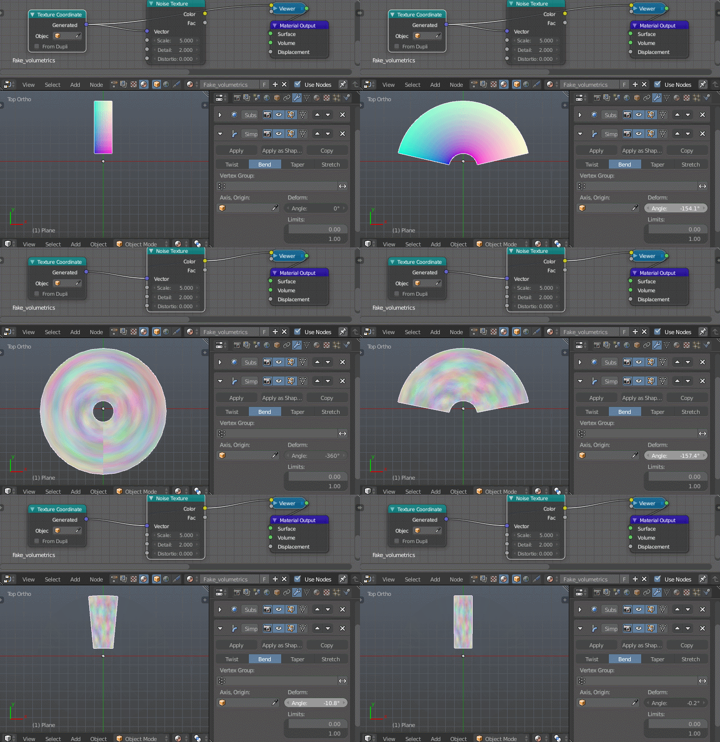
One way to do this is by stretching the mesh, so to speak, rather than the texture. When a mesh is bent by the deform modifier, cycles will give us the coordinates of the unbent mesh, but deformed to match the mesh's deformation. To see how this is useful, consider the following gif:
Unfortunately, for some reason this only works for the surface coordinates; we get undeformed coordinates if we try and use them for a volume shader. However, it's possible to fake volumetrics using an array modifier.
The complete process:
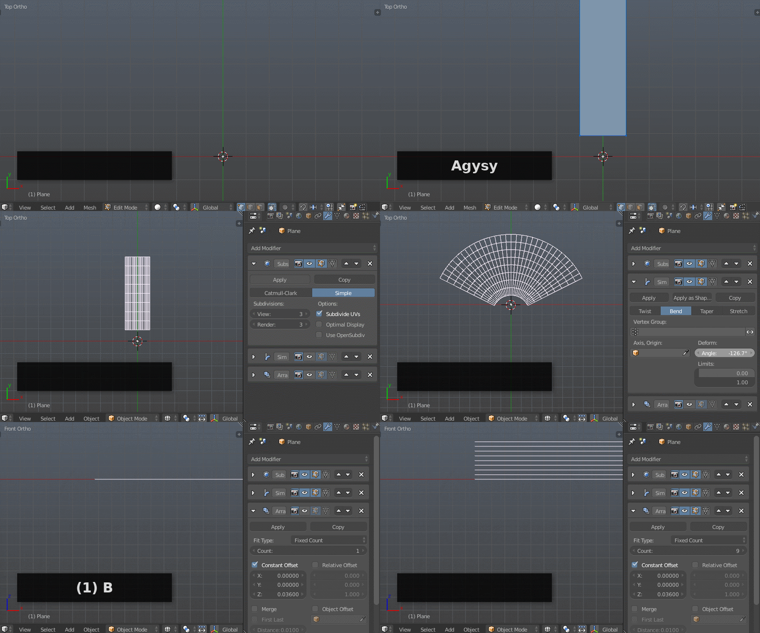
- Create a plane (⇧ ShiftA> Mesh > Plane) and give it a few loopcuts (⎈ CtrlR)
- Add a subsurf modifier, set it to Simple and increase the number of subdivisions a bit.
- Add a simple deform modifier, set it to Bend, bend it 360°
- Add an array modifier, use the Z constant offset to make a "stack" of planes.
- Finally, slap on a shader such as this:
 The Scale nodegroup performs identically to the scale component of the mapping node while in Point mode. I use it instead in case I wish to connect something to any of the scaling factors, and just because it takes up less screen real-estate if I don't need any of the other transforms
The Real Way
The above method renders fast, but doesn't work so well if you get too close or want to go inside it.
Instead of using some modifier trickery to get blender to generate the coordinates we want, we can generate them ourselves by transforming the default generated coordinates to polar coordinates.
This has the distinct advantage of letting us use real volumetrics:
Nothing special with the object this time, just a solid, flat, doughnut-shaped mesh with no modifiers. Everything is done in the shader:
The first group ("Centered Coordinates") takes the default generated coordinates (which are the normalized object dimensions, i.e. the entire object is within the 0..1 range, with each extreme of the object along a given axis being either at 0 or 1), and subtracts .5 from the X and Y so that 0,0 is in the middle of the object.
The next group ("Polar Coordinates") is where the important stuff is. It transforms the X and Y coordinates of the input to polar coordinates. It leaves the Z untouched. What this transformation does can most clearly be seen by comparing the way the X and Y coordinates vary before and after:
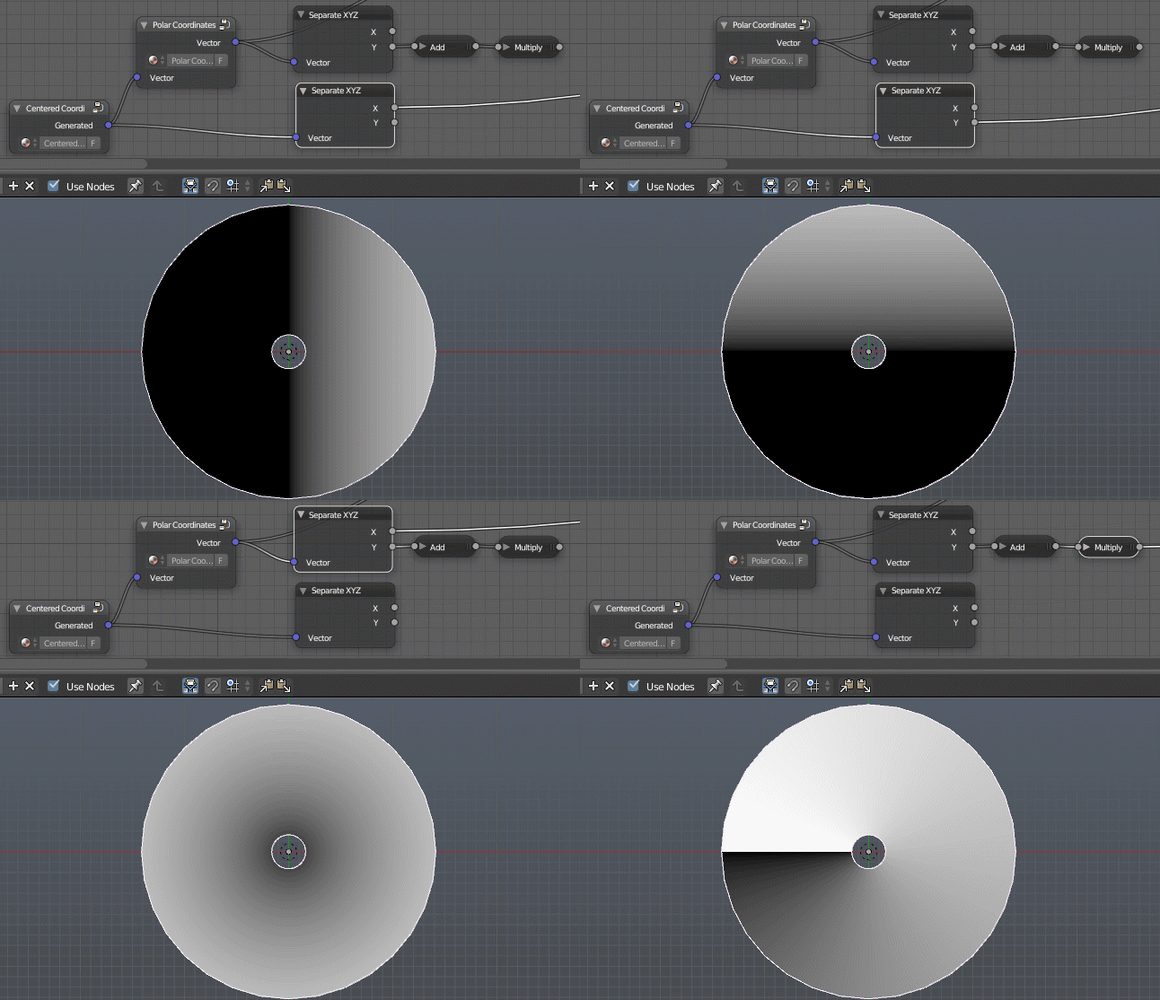
The add and multiply nodes on the polar Y axis in this example just transform the values from -1..+1 to 0..1 for the purpose of visualization
Before the transform, the X and Y vary along the axes. After the transform, the X varies with distance from the center, and the Y varies with angle to the center.
From here on, the shader looks pretty much like that of the first method. The only major difference being the use of a musgrave texture instead of a normal noise texture, which is, of course, completely up to interpretation.
-
$\begingroup$ Looks fantastic, but im confused with the whole polar coordinates thing. What are the advantages of messing with the coordinates? $\endgroup$– eromodCommented Dec 12, 2016 at 23:13
-
$\begingroup$ Fantastic solution and answer! How do you avoid a discontinuity at the point the polar coordinates wrap around at 360 degrees? I can't spot any join in the animation. Nice work! $\endgroup$ Commented Dec 12, 2016 at 23:36
-
$\begingroup$ @RichSedman I don't, the noise texture had enough high-frequency detail to effectively hide it. There are a number of approaches you could try to take here, e.g. mirroring, blending, or using a seamless texture (this last one would likely require OSL) $\endgroup$– gandalf3Commented Dec 13, 2016 at 6:18
-
$\begingroup$ @eromod You mean the advantage of the second method over the first? With the first, the "volumetrics" are faked using a stack of 2D planes, which becomes apparent when viewed edge-on or from inside. The second method avoids this by eventually doing what the bend modifier did, but in-shader. $\endgroup$– gandalf3Commented Dec 13, 2016 at 6:30
Is this similar enough?
Here is the node setup
 I used a rotating cylinder with motion blur
texture coordinate node--where the coordinates for the texture are coming from.
mapping node--so you can transform the texture
musgrave texture node--procedurally generated blobs
greater than node--increases the empty distances between the blobs
multiply node--makes the blobs brighter
emission node--color of blobs
material output node--assigns texture to the volume of the object.
-
4$\begingroup$ please add more detail to your answers. Please explain the logic behind your nodes. Why you choose one value over another or what the math nodes are doing. Looking at the node tree might look obvious to you but will not help a new user understand how to do things... $\endgroup$– user1853Commented Dec 10, 2016 at 3:58

