31
$\begingroup$

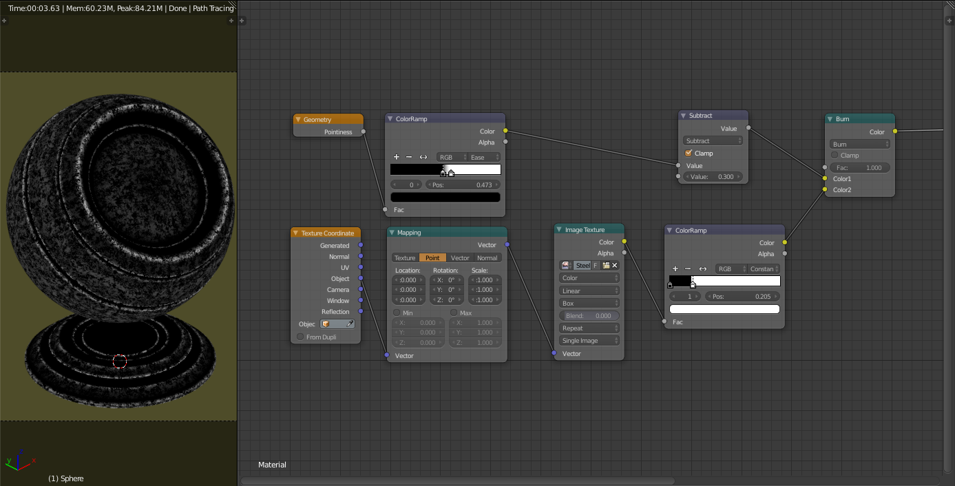
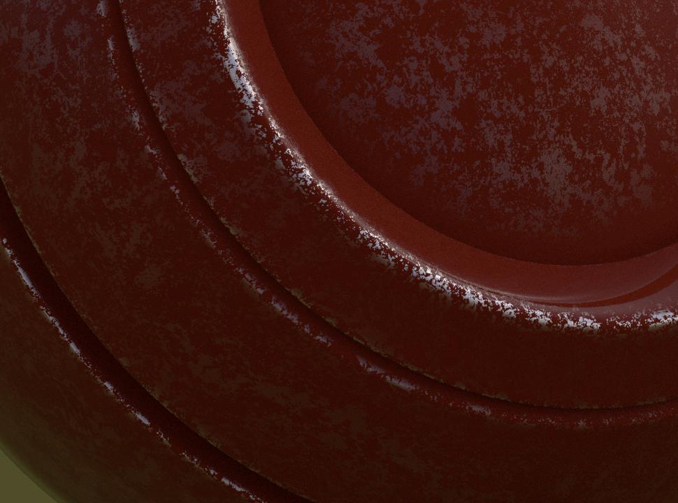
I'm trying to create a procedural mask to affect the sharp edges of my model using the Pointiness output from the Geometry node, leading to the eventual idea of using it to create customisable weathering effects, such as this.

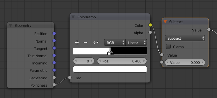
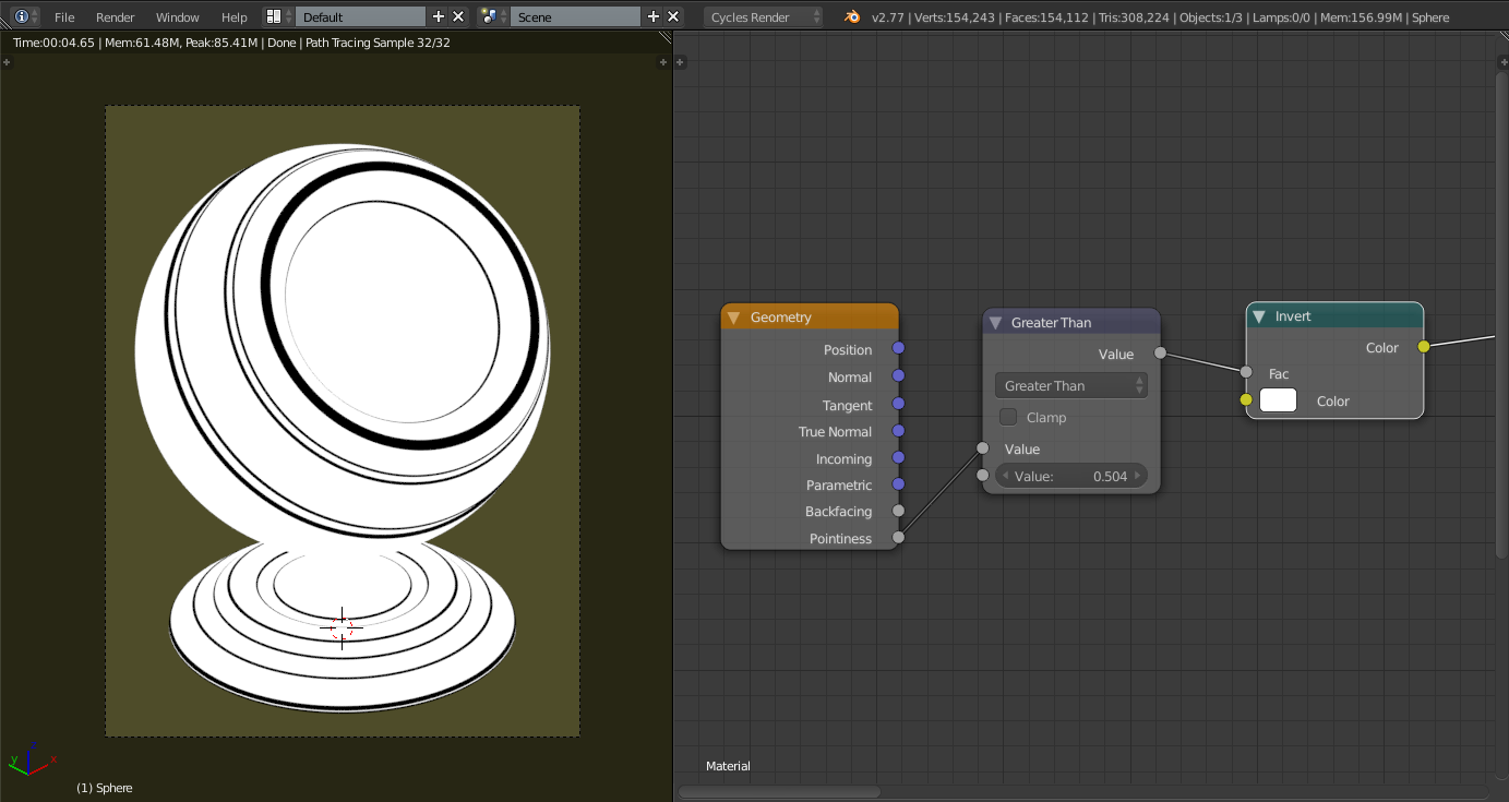
This is the base setup that I've got so far. Working @ Node Setup

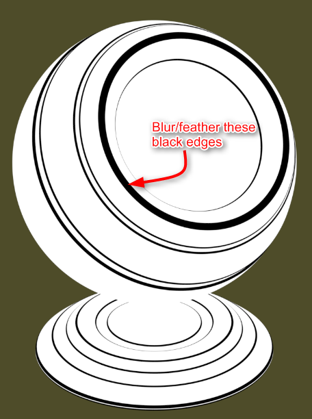
How is it possible to blur/feather the black edges of the mask so that they would essentially expand across the object until the whole object is rendered black? Description

I've had a look at both of the go-to texture blur methods suggested for cycles found here and here however these seem to rely on there being a vector input/output for the texture, which is not the case in my example.

The Procedural Cracks tutorial by CGMasters came closest to what I was trying to achieve with the 'Worn Edges' section of the video, but I didn't have any success trying to convert it to my situation.

Any ideas would be massively appreciated! :)

EDIT: Not sure if it was clear enough from the description but I'm trying to steer clear of baking/UV-Unwrapping/the Works on this one... Purely procedural :)

UPDATE: I've made a couple of updates to the shader which has given me slightly better results, although it's still not quite there and the mask blur/expansion issue is still not successful.

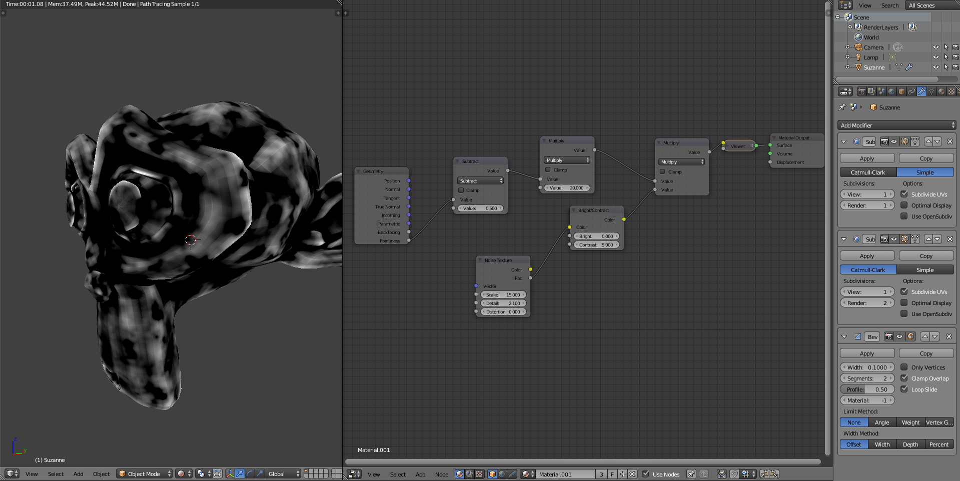
This is what it now looks like: Update Progress

The issue is now coming from the grey values of the mask 'leaking' out across the whole mesh and not stemming from the black values... if that makes sense? :P Close, but Issues

In researching weathering effects in blender, I stumbled across this GIF, which is exactly what I want to achieve?

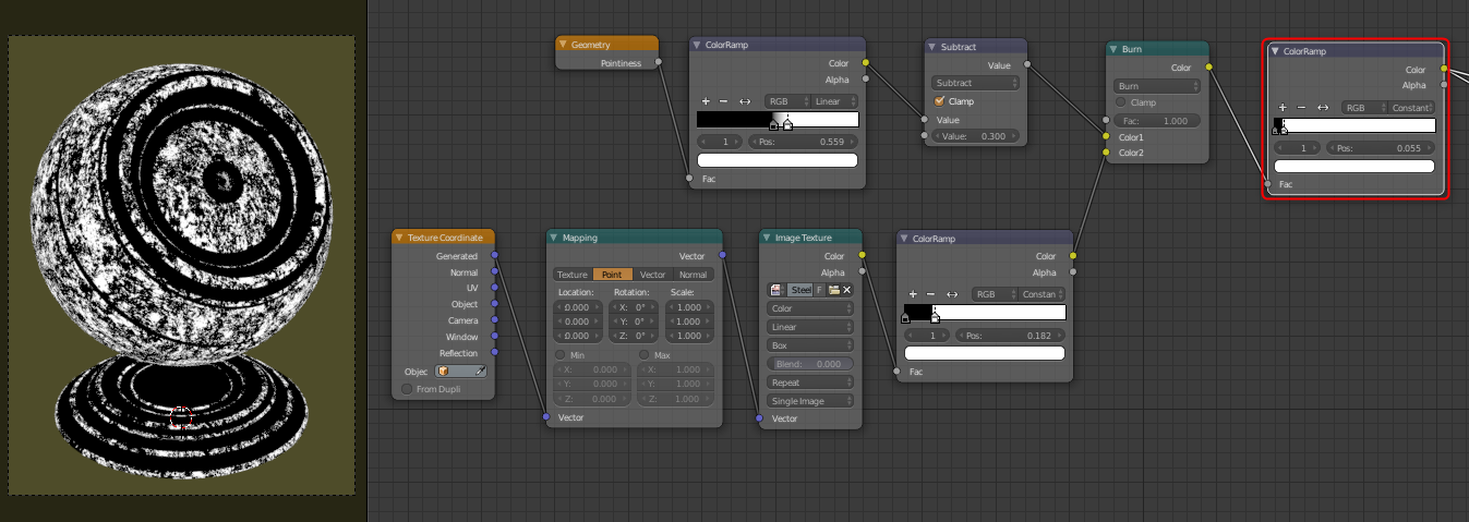
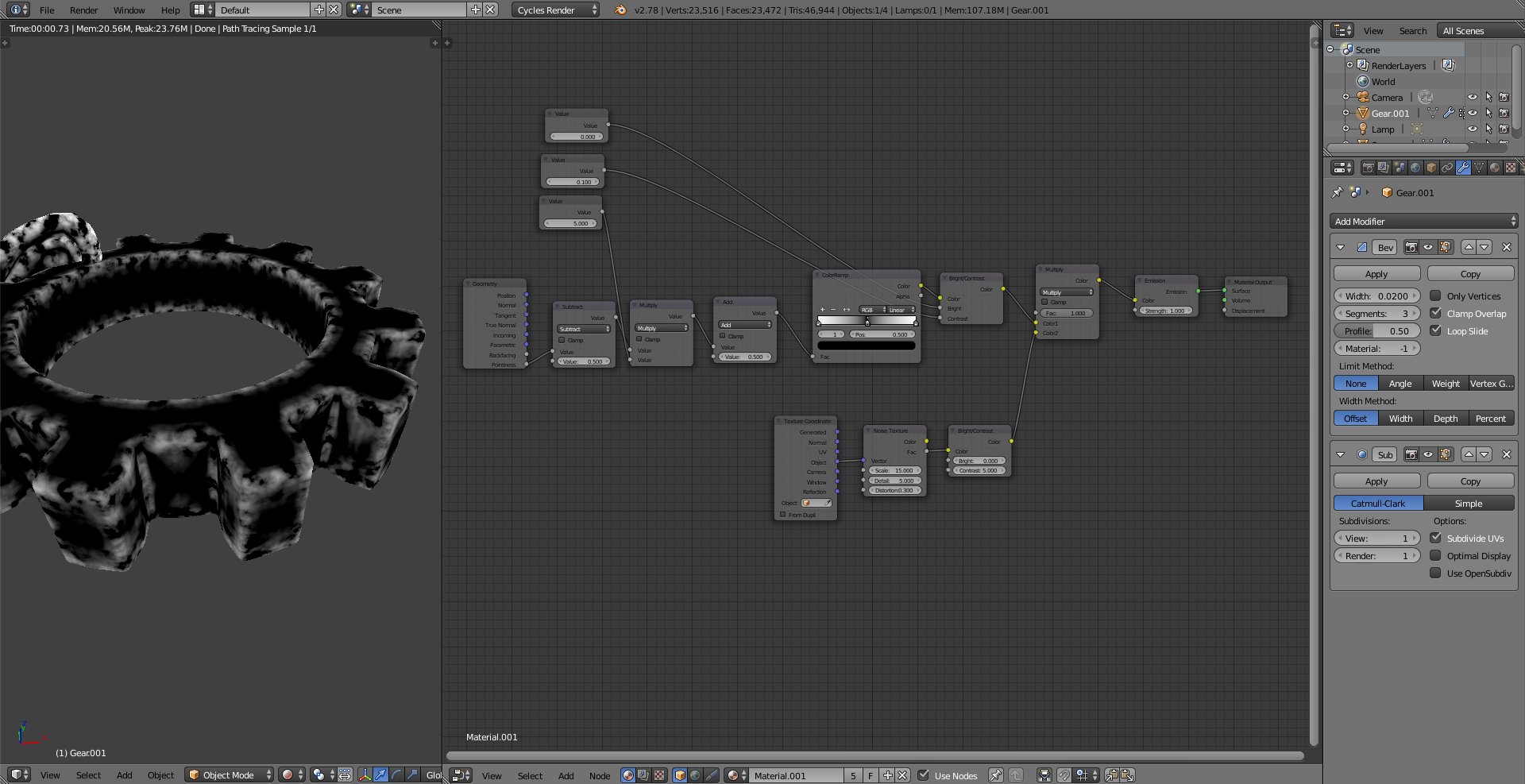
UPDATE 2: Still no luck achieving the desired effect in the gif, however I feel I'm slightly closer from adding another colour ramp node after the previous ones.

Update 2

Does anyone have any more ideas?

UPDATE 3: Found a working solution, added an answer below if people are interested :)

$\endgroup$
6
  • $\begingroup$ Here´s the source for the gif file you want to mimic. It´s from a Node Pack on the Blender Market you can buy for $20 called "Stencil Kit: Dynamic weathering node kit" by Eric Edelo. Well worth the money IMO. Posting his node setup here would be rude towards him so that´s the best help I can give you. $\endgroup$
    – user30344
    Commented Sep 9, 2016 at 13:28
  • $\begingroup$ Where can I find the model used in this question? The nearest I could find was this one blenderdiplom.com/en/downloads/… but it's less angular and more rounded. $\endgroup$ Commented Dec 10, 2016 at 7:55
  • $\begingroup$ Where can I get the model you use for testing? $\endgroup$
    – piegames
    Commented Dec 10, 2016 at 9:57
  • $\begingroup$ You know it wont be consistent effect because it's completely dependent on vertex density, what works for some part won't work for others. Its not possible to make universally good effects with pointiness, you need to fine tune the ramps case by case anyway. This goes for the node kit mentioned above, I assume it's using pointiness since there is no per pixel curvature in Blender. $\endgroup$
    – kheetor
    Commented Dec 10, 2016 at 15:37
  • $\begingroup$ @whotheme thanks for the heads up. Spend a while away from the project but picked it up again recently. Ended coming up with a solution that seems to work, although I actually bought Stencil Kit to ensure that my solution wasn't the same- and it isn't :) Going to work on a tutorial below. $\endgroup$
    – Hexbob6
    Commented Dec 15, 2016 at 21:17

4 Answers 4

32
+50
$\begingroup$

Creating Procedural Weathering Effects in Blender


Okay so I ended up developing a solution to this question a couple of months back, but I see it's gained a lot of interest recently so I thought I'd post a tutorial on how I went about solving it.

The weathering effects basically involve creating a Worn Edge and Cavity Dirt mask, which can then be used to blend between 2 or more shaders within one material.

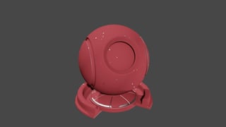
This is along the lines of what we'll be creating.
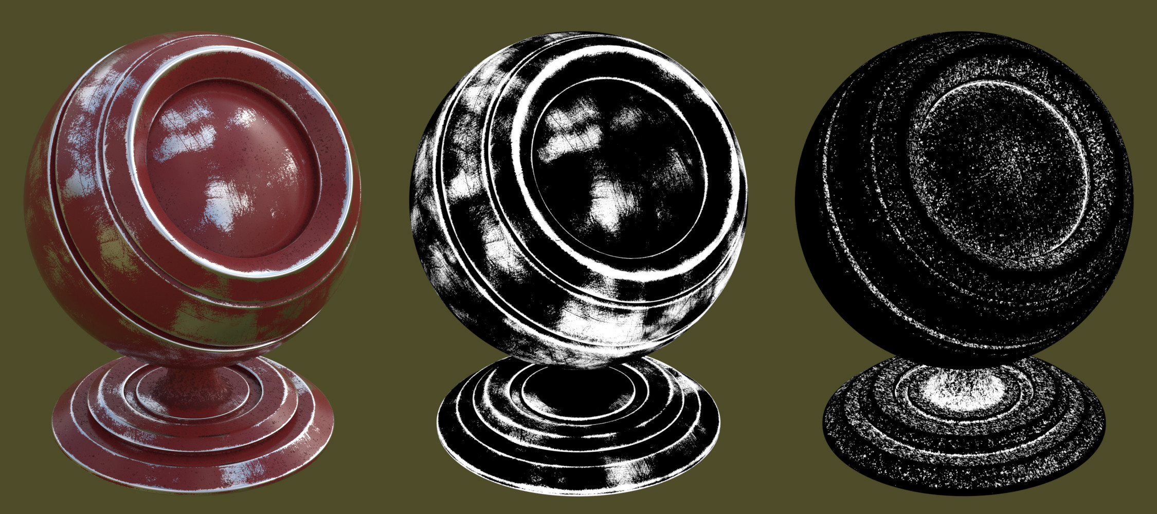
Final Result

(NOTE: This effect works best for objects with a high poly-count, so throw your object through a sub-surf modifier.)


The Edge Wear Mask Node


1. So to begin, we'll create a simple material a mix between a Diffuse and Glossy shader. In my final image I used Blender Guru's PBR Dialectric and PBR Metallic node groups to give the material a little bit of added realism, so I'd recommend checking those out :)
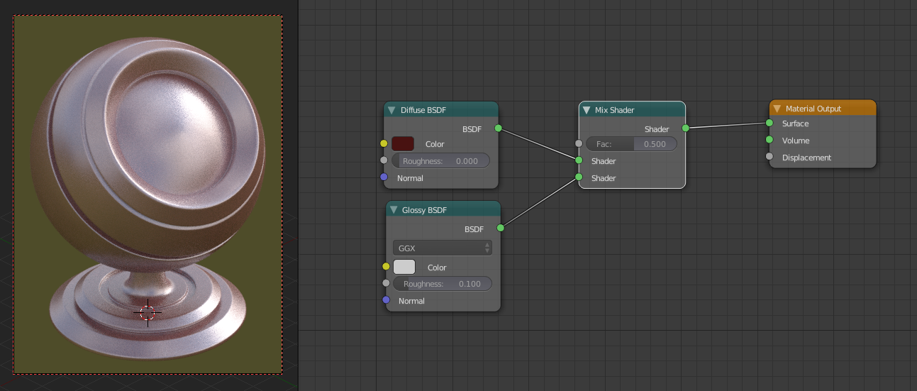
Step 1

2. Now we've set up the base material we can move it off to the side and concentrate on building the Worn Edges Mask node group. We'll do this by first adding in a Geometry node, and connecting the Pointiness attribute to the input of a Color Ramp node. I set the black stopper to a position of 0.47, and the white stopper to a position of 0.514.
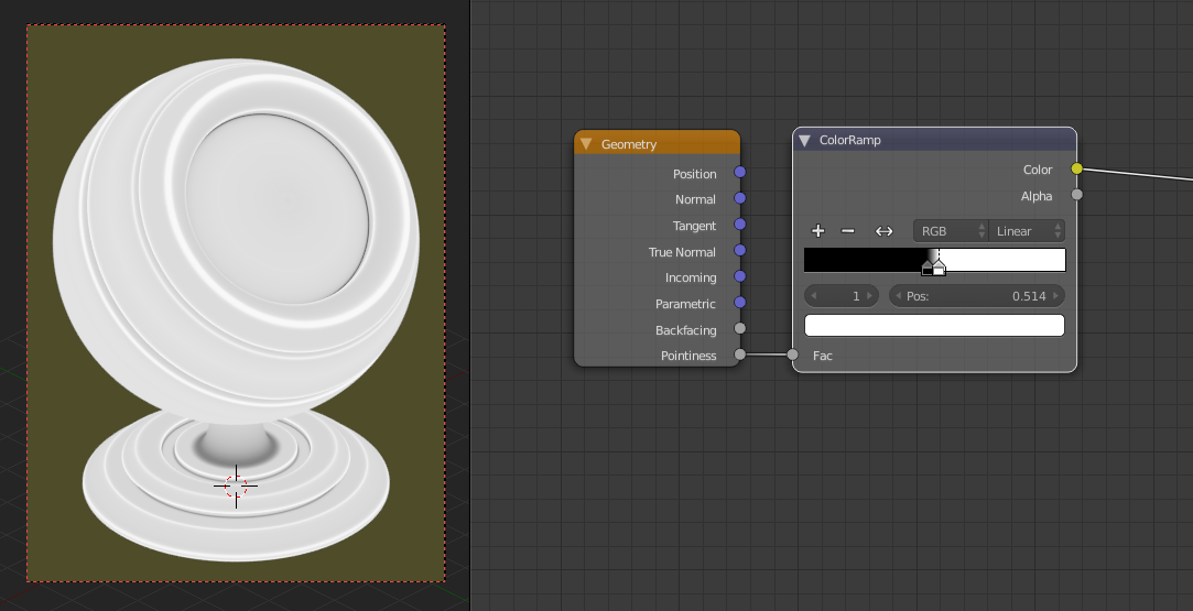
Step 2

3. Next we can add in a Math node and set its mode to Subtract. Plug the output of the Color Ramp into the top input of the Math node and set the bottom value to be 1. Then, add in a MixRGB node, change its blending mode to Add and the Fac to 1, and plug the output of the Math node into the top Color input. Finally, we can add in a Noise Texture node and plug the Fac output into the second Color input of the MixRGB node. (Don't worry, it's less complicated from here!).
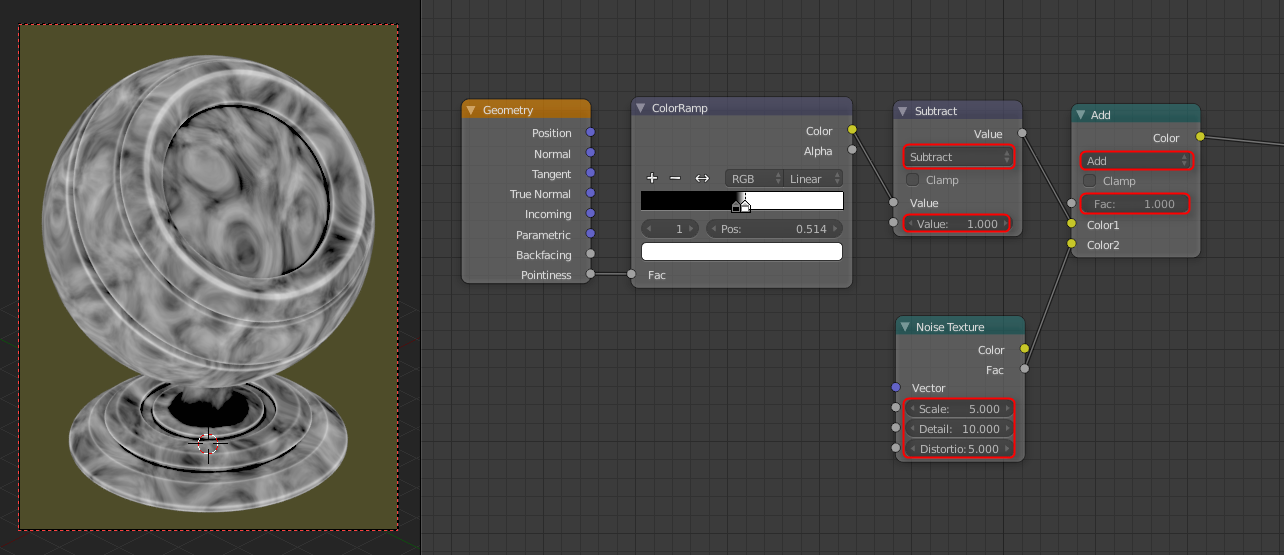
Step 3

4. I'll go into more detail on the Noise Texture later on, but it is basically controlling the shape of our edge weathering, which bits are chipped, etc. Anyway, now we can add in another Math node and set its mode to Greater Than. This is where it gets fun- plug the Color output of the MixRGB node into the top input of the Greater Than node and begin adjusting the bottom value. You should see the white areas 'shrinking' towards the edges, the closer you drag the slider to 1 (I found a value of 0.35 to look good here).

And that's the basis of our edge weathering mask! All black areas of the mask will later show the Diffuse material, and the white will be Glossy.
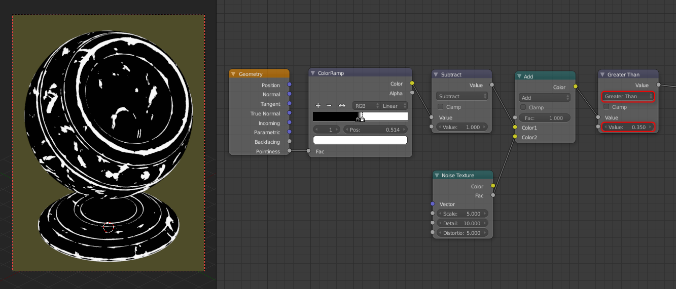
Step 4

5. Let's plug our mask into the Fac input of the Mix Shader to see how it looks... not too bad! Has a chipped paint feel to it.
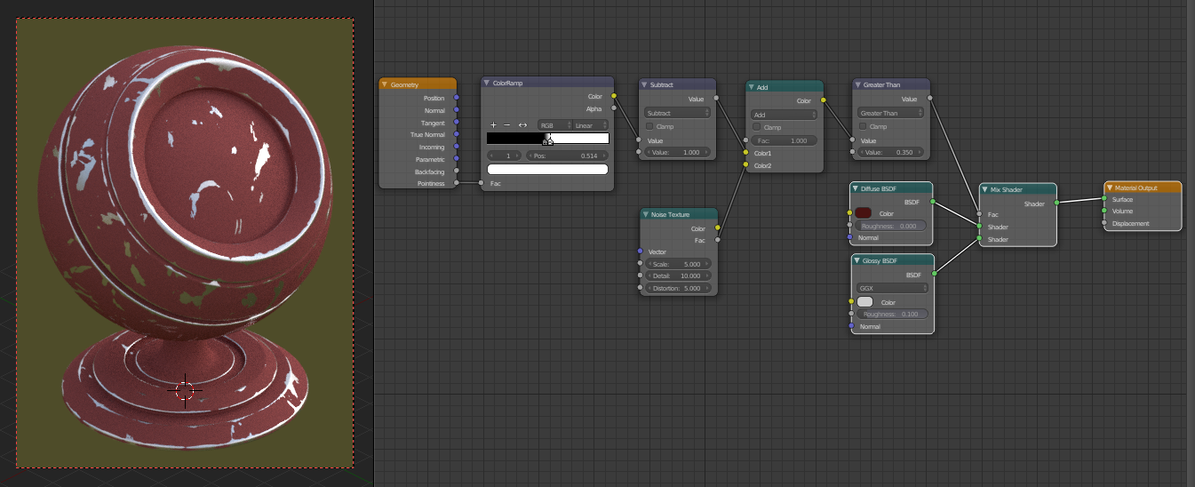
Step 5

6. One last thing we can do before packing it all into a node group is add a Bump node and connect the output of the Greater Than node into the Height input. Optional if you want to use this effect, sometimes it can give an odd outline around the border between the 2 shaders, but often it can add some depth, making the materials seem layered.
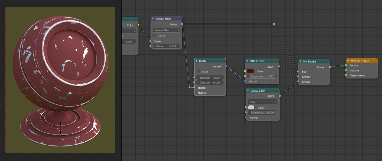
Step 6

7. Now we can select the Geometry,Color Ramp,Subtract,Add,Greater Than and Bump nodes, and hit Ctrl+G to create a node group out of them.

Step 7

8. Then we'll connect the noodles to the appropriate group input and output slots and rename them accordingly (see the screenshot).
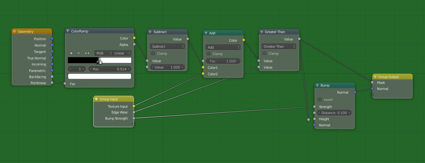
Step 8

9. Finally we can rename our Node Group to Worn Edges... and that's it! We've successfully created the edge wear mask node! :)
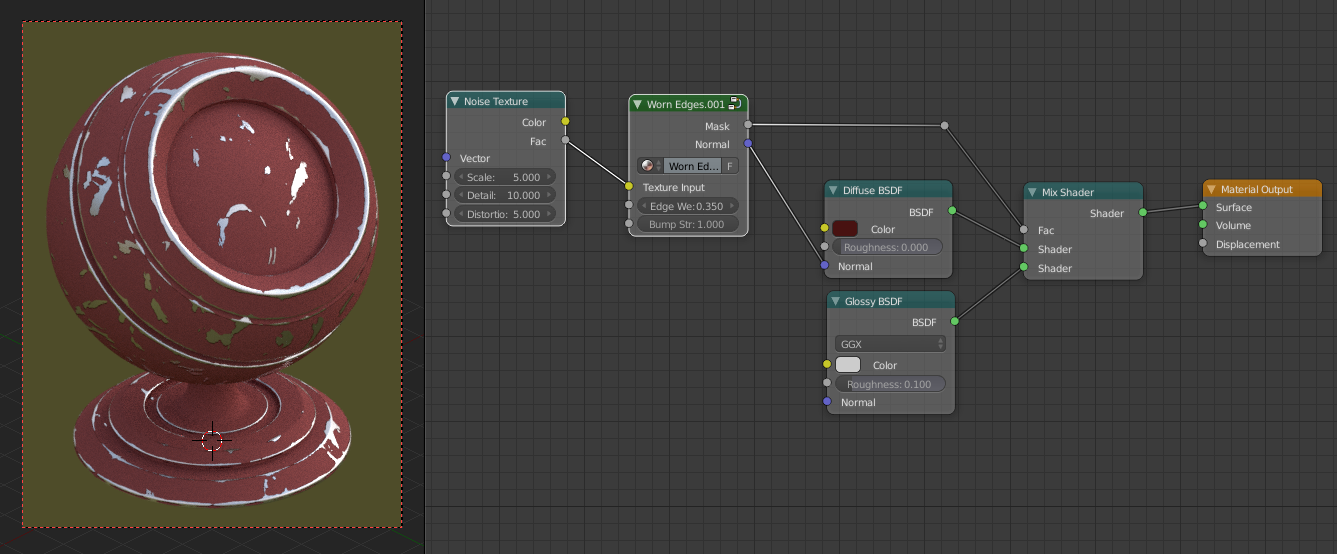
Step 9


The Cavity Dirt Mask Node


1. Now, setting up the Cavity Dirt is ridiculously simple now that we've completed the previous steps. First, add another Diffuse and Mix node to the material, like so...
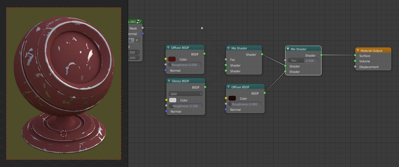
Step 1a

2. Duplicate the Noise Texture and Worn Edges nodes. Adjust the parameters of the Noise Texture node to how you'd like the cavity grime to look. Now, click the '2' next to the Worn Edges name on the node group to make the duplicate a single user copy, and rename it to 'Cavity Dirt'.
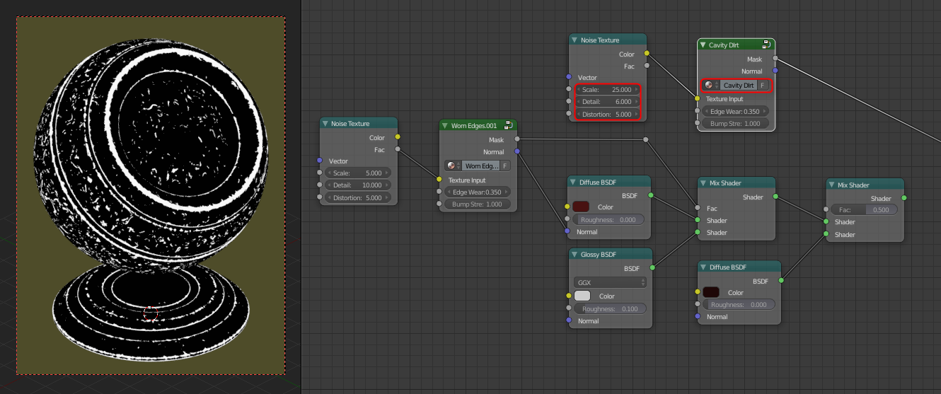
Step 2a

3. Finally, hit Tab to go into the Cavity Dirt node. Find the Color Ramp node and hit the flip ramp button to invert the ramp from 'black -> white', to 'white -> black'.
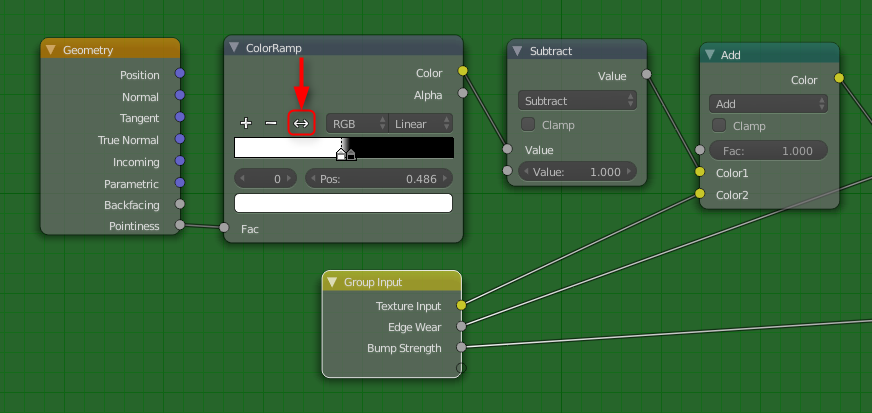
Step 3a

4. And it's as simple as that! Tab out of the node group and tweak the settings, and you'll be able to see a mask that only affects the cavities of the object.
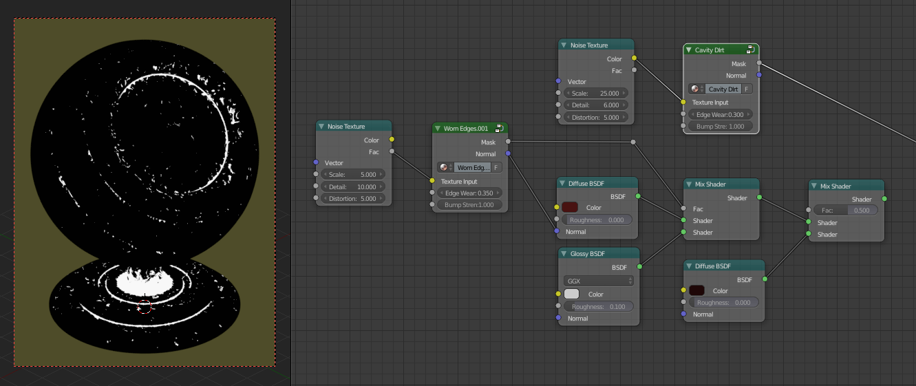
Step 4a

5. How it looks when combined with the second Diffuse shader.
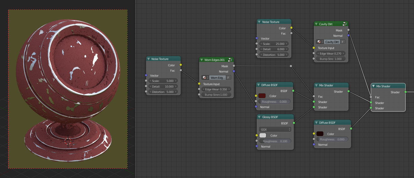
Step 5a


Using Image Textures


Although the Noise Texture node used as the shape mask doesn't look toooo bad * cough *, I've found that using image textures can give much more appealing results if you use generated box mapping.

These tend to work best if they're greyscale, and I've found dirt masks/grunge maps tend to look good. The ones I used in my original image came from Max Textures. I've found they provide some nice, high quality, seamless ones for free.

Textures1


Limitations


Although this technique works very well for most applications, there are a couple of limitations to the method...

  • As mentioned by other answers and at the start, the fact that this setup uses the Geometry node's Pointiness attribute means that it will not work at all, or at least not well for low-poly models, as there simply aren't enough vertices.
  • Some texture maps work better than others, currently I haven't been able to distinguish exactly what causes one to work well and another not so much. My best guess is it's the contrast.
  • Sometimes the values to bump up edge wear, for example, can be very tight. That is, there can be a drastic jump in how the mask covers the object with a value change as little as 0.1. Again my best guess is that this is due to contrast when using image textures.

Other than that enjoy! Hope it helps people out, and don't forget to upvote if you liked it! :)
$\endgroup$
5
  • $\begingroup$ Nice answer regarding adding dirt and wear and worth an upvote... but... it doesn't seem to address the problem posed in the question - how to blur/feather the Pointiness - as mentioned in your Limitations at the end. I was never really happy with Pointiness and its lack of configurability and am trying different solutions to get a similar but configurable effect - one tht works with flat surfaces as well as more rounded meshes - but it's not quite there yet. $\endgroup$ Commented Dec 16, 2016 at 10:40
  • 2
    $\begingroup$ Definitely deserved the bounty! $\endgroup$
    – 10 Replies
    Commented Dec 16, 2016 at 20:22
  • $\begingroup$ @RichSedman Thanks for the input, and you're right, but I think it was probably my fault for being slightly ambiguous with what I meant when I posted the original question. Initially I was hoping that I would be able to find a way to expand the mask away from the edges, and have it become more blurred the further away it spread, and that this would help me make the input texture 'bleed' away from the edges... if that makes sense... cont. $\endgroup$
    – Hexbob6
    Commented Dec 16, 2016 at 21:38
  • $\begingroup$ @RichSedman cont... In then end the 'bleeding' effect was still possible with the solution I developed, although you're right, technically it doesn't solve the feathering part of the question. I think that whilst the pointiness node is solely dependent on mesh geometry, there's no foreseeable way to use it for low-poly objects, and thus the best option for them would be to bake cavity maps, etc and use them in place of the pointiness color ramp. Let me know if you come up with any better solutions though, I'd be interested to see what you find. $\endgroup$
    – Hexbob6
    Commented Dec 16, 2016 at 21:43
  • $\begingroup$ And @10Replies thanks a tonne! Glad you found it helpful :) $\endgroup$
    – Hexbob6
    Commented Dec 16, 2016 at 21:45
4
$\begingroup$

You can pass the Pointiness value through Color Ramp, move the color stops towards the center until you get desired initial state, then pass it trough Add or Subtract math node and animate the bottom value to offset the color until it covers all the object.

enter image description here

$\endgroup$
1
  • $\begingroup$ Thanks for the reply Denis, though it's still not quite there unfortunately- I'll add in the updated material to my original post. $\endgroup$
    – Hexbob6
    Commented Jun 16, 2016 at 19:43
2
$\begingroup$

I played around with some settings and this what I got after having deleted a lot of math:

screenshot

It doesn't look really good now, but it works. The idea is to manipulate the pointiness until it covers the areas you need and then mix it up with some noise. Tweak the value of the subtract node to control how much Pointiness you want to have (Use a ColorRamp for good results). The first multiply is to add contrast (Just found out that both nodes can be replaced by a Bright/Contrast and it will give you the same).

Then, mix it up with some noise to give it texture. You probably won't stick to multiply for combining and add more noise textures, but this is just a proof of concept.

EDIT

I changed my node setup a bit, the results are better and easier to control now. It also takes care of edges pointing inwards. You probably want to change the noise texture by a rust map or so.

The bottom value input is the main multiplier. It will adjust brightness and sharpness of the edges. The other two are controllerss for the bright/contrast node to furtherly adjust the value. For testing, mute the multiply node to disable the noise texture until you get proper results.

enter image description here

$\endgroup$
1
$\begingroup$

Solution for Eevee (works only with shade set to smooth!):

since pointiness doesn't work in eevee we wil just have to fake it 🥳.

enter image description here

you can then use the shader in Hexbob6's answer to make the shader:

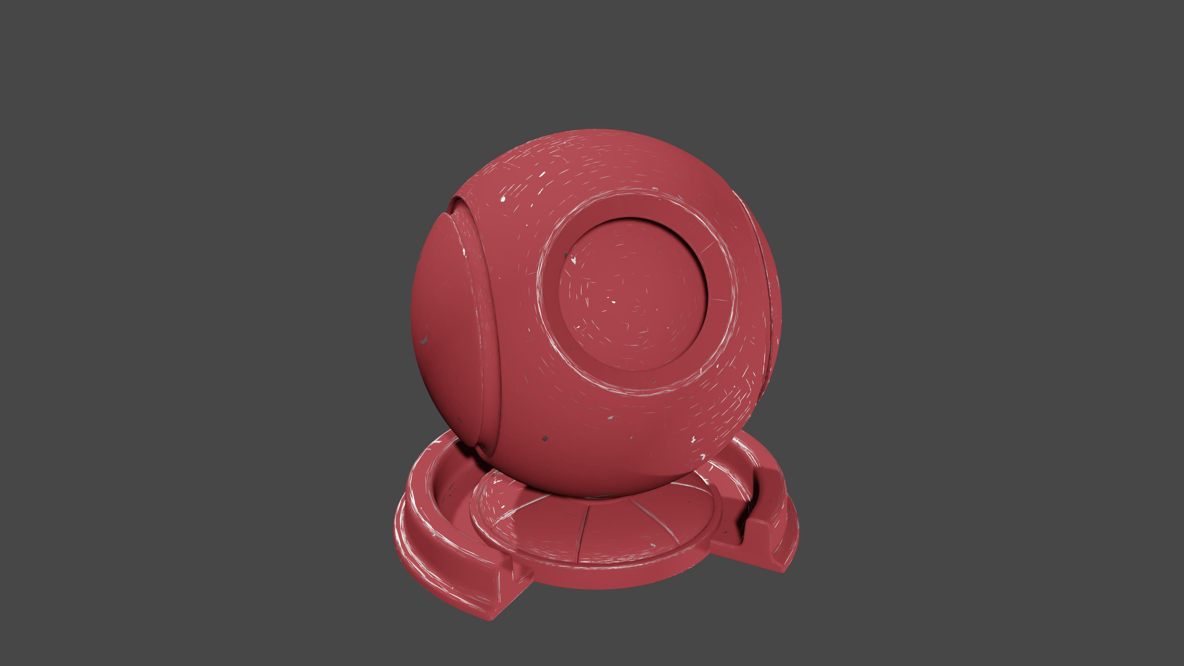
image:worn off shader ball

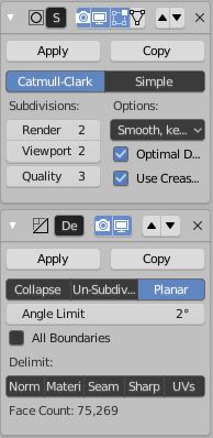
hmmm, not quit there yet, lets add a subdivision mod and a planar decimate mod:

image: subdivision survace 2 and decimate set to planar, angle 2

Result:

enter image description here

Heck yeah!

$\endgroup$

You must log in to answer this question.

Not the answer you're looking for? Browse other questions tagged .