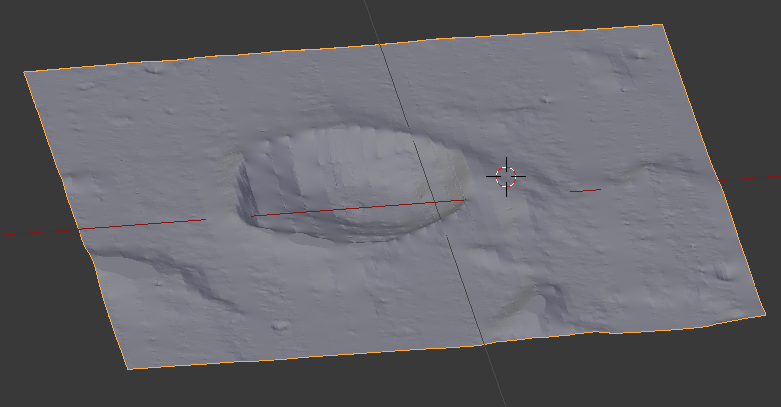
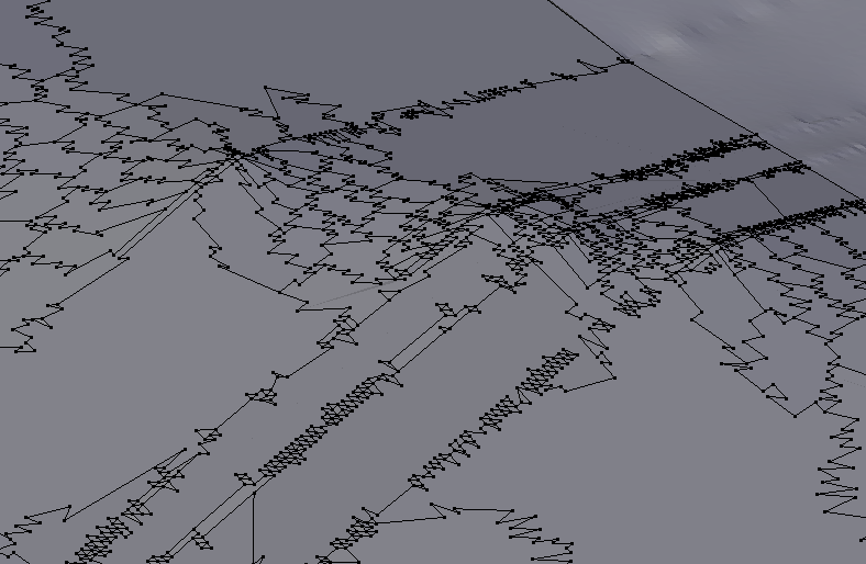
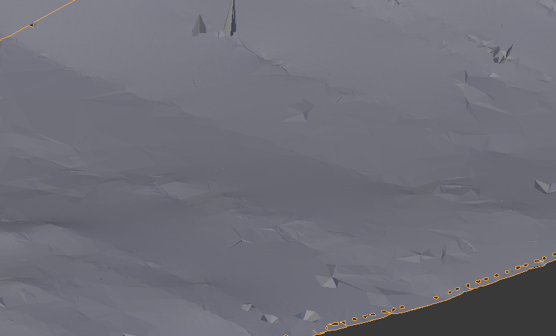
Because the mesh is fairly simplistic in terms of shape, I would recommend rendering out the Z-Pass/Z-Depth (setting your camera to your top view before render), and saving that image. Then you can start with a new plane, and use the displace modifier, using that rendered image as the displacement texture. Once you have that in place, you could subdivide your mesh until it fits your needs, and add sub-surf modifiers to smooth it out.
I will attempt to circle back around to this post shortly, but as time allows, in order to post screenshots of the process, and step by step text to finalize this answer.
OK, sorry that this took so long, but I personally had to verify the steps to get this done, because it has been a little while since I have used this method, and I wanted to make sure that the steps were correct before posting.
To Get the Z-Pass Image Rendered
Go to top view using Numpad 7.
Ctrl+Alt+Numpad 0 - to set your camera to the active view.
In the Render Panel, Adjust your render size to a proportion equal to your mesh dimensions.
Switch to the Data Panel (with your camera selected it's the one that looks like a movie camera - not the render panel).
Set your camera to Orthographic.
Copy the X & Y Locations to your camera's X & Y Locations.
Adjust your Orthographic Scale until the mesh fills the Camera.
Turn Limits on.
In your 3D View go to a front or side view and change the view to orthographic (Numpad 5).
Adjust clipping start to just above the mesh (the limit line will move toward the top as you increase the start value).
Adjust clipping end to just below the mesh (the far end of the limit line will move toward the bottom of the mesh as you decrease
the value).
Go into the Node Editor and into Compositing Mode.
Check 'Use Nodes' as soon as you do, there should be a 'Render Layers Node' as your input, and a 'Composite Node' as your output.
Add The following three nodes:
- Add >> Vector >> Map Range
- Add >> Color >> Mix
- Add >> Output >> Viewer (optional - If using this make sure that you have backdrop checked in the compositor toolbar.)
From the 'Render Layer Node' Take 'Z' and input it into 'Value' of the 'Map Range Node'.
Set 'Min' & 'Max' to the same values that you clipped your camera to in steps 10 & 11.
Take the 'Value' Output of the 'Map Range' and input it into 'Fac' of the 'Mix Node'.
Verify that the top image is 100% white .
Set the bottom image to 100% black.
Take the 'Image' Output of the 'Mix Node' and input it into the 'Composite' & 'Viewer Node'.
Render and save this image for Displacement.
For the actual Displacement
I'm going to describe using the Images as Plane Add-on, as I believe it is the easiest method for this. If you don't have it enabled, please either enable it to follow along from the User Preferences, or Manually add your plane and UV unwrap it from the top view.
Add >> Mesh >> Images as Planes.
Browse to your saved file from the Z-Pass Instructions Above.
With the new Plane Selected, go into the Modifier Panel and Add the Displace Modifier.
For the Texture Just go into the drop down and select the image that you just imported via steps 1 and 2.
Set Texture Coordinates to UV.
In the Modifier (at the top) Enable 'Display Modifier In Edit Mode'.
Sub-Divide your Plane W >> S.
Adjust Mid Level & Strength to suit your liking.
Repeat Steps 7 & 8 Until you are satisfied with the outcome.
Note:
There are faster methods, such as Shrinkwrap, or Face Snapping your verts in edit mode, etc... BUT, once you actually do all these steps and get used to them, you will find that this is actually very quick as well.
However this method allows you to keep the detail information in texture form, and adjust your mesh topology up and down separately without worrying about losing information.
This also has great usage capacity when your camera moves away in distance, and you can modify it in a procedural driver sort of way to lessen poly-counts (via Sub-Surf Modifier Driver) in the rest of your scene (super useful for animation render times when things come in and out of focus or change in foreground/midground/background).


X> Limited Dissolve and execute Degenerate Dissolve from Mesh > Clean-Up menu. Beware that dissolving may delete more vertices than expected; also these tools won't repair everything. If you do need all that geometry as real one consider either retopology or displacement texture as already proposed. If you don't you could bake normal map. $\endgroup$